Page is loading ...

Owner’s Manual
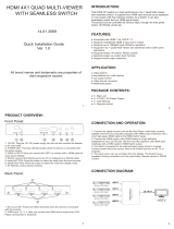
HX-4400S
4x4 HDMI/VGA Integrated Matrix Switcher with
Scaling, Multi-View, and Video wall Function
PureLink
TM
535 East Crescent Avenue
Ramsey, NJ 07446
USA
Tel: +1.201.488.3232
Fax: +1.201.621.6118
E-mail: sales@purelinkav.com
www.purelinkav.com
For order support, please contact your local dealer.
For technical support, please contact us at support@purelinkav.com

PureLink by Dtrovision
2
TABLE OF CONTENTS
Chapter 1. Product Overview & Specification
1.1 Safety Precautions --------------------------------------------------------------- 3
1.2 Declaration of Conformity --------------------------------------------------------------- 4
1.3 What’s in the Box --------------------------------------------------------------- 4
1.4 Product Introduction --------------------------------------------------------------- 5
1.5 Product Specification --------------------------------------------------------------- 9
1.6 Front View --------------------------------------------------------------- 10
1.7 Rear View --------------------------------------------------------------- 11
1.8 IR Remote Control --------------------------------------------------------------- 12
1.9 IR Control --------------------------------------------------------------- 12
1.10 Installation Guidelines --------------------------------------------------------------- 13
1.11 Communication Settings --------------------------------------------------------------- 14
Chapter 2. Communication Code Configuration
2.1 Control Programmer’s Guide ---------------------------------------------------- 15
2.2 Overview ---------------------------------------------------------------------- 15
2.3 Command Code Formats ----------------------------------------------------------- 15
2.4 General Rules for Command Codes --------------------------------------------- 16
2.5 Command Ack Value Response ---------------------------------------------------- 17
2.6 Connecting Switches --------------------------------------------------------------- 18
2.7 Disconnecting Switches ----------------------------------------------------------- 19
2.8 Connection Status Check ----------------------------------------------------------- 21
Chapter 3. Additional Information
3.1 Manufacturer’s Warranty (3-Year) ------------------------------------------------- 23
3.2 Customer Service ------------------------------------------------------------------- 23

PureLink by Dtrovision
3
Chapter 1. Introduction
1.1 Safety Precautions
All safety instructions should be read and understood before the unit is operated.
The owner’s manual and safety instructions should be retained for future reference.
Unplug this unit from the wall outlet before cleaning. Do not use liquid or aerosol cleaners. Use a damp
cloth only.
Keep away from wet, magnetic, and flammable surfaces or substances.
Always use the correct external power supply (indicated on the product label) when operating this unit.
This unit may be equipped with a 3 wire grounding-type plug - a plug having a third (grounding) pin.
This pin will only fit in to a grounding type power outlet. If you are unable to insert the plug in to the
outlet, contact your electrician to replace your obsolete outlet.
Air vents should be kept clean and unobstructed at all times.
Please refrain from using frayed power cords and damaged wall outlets.
Do not place any heavy objects or equipment on top of the unit.
To prevent electrical damage, TURN OFF the power to this unit before inserting or removing
INPUT/OUTPUT slot cards.
If you experience any malfunctioning of product or have any question as to operation of the
product, please contact our customer service center.
PureLink
TM
Tel: 201.488.3232
Email: support@purelinkav.com

PureLink by Dtrovision
4
1.2 Declaration of Conformity
According to Council Directive 73/23/EEC (February 19, 1973) on the Harmonization of the Laws of
Member States relating to Electrical Equipment; Council Directive 89/336/EEC (May 3, 1989) on
Electromagnetic Compatibility; Council Directive 93/68/EEC (July 22, 1993)-Amending Directives
89/336/EEC (MC) and 73/23/EEC (Low Voltage Equipment Safety), and/or CPU Boards and Power
Supplies used Council Directive 93/68/EEC with Matrix, Dtrovision LLC, 535 E Crescent Ave Ramsey, NJ
07446 201-488-3232, declares under sole responsibility, that the product identifies with 93/66/EEC of the
Council Directive Low Voltage Equipment Safety. Each product marketed is identical to the representative
unit tested and found to be compliant with the standards.
1.3 What’s in the Box
Main Frame: HX-4400S
Power Adapter – DC 12V, 2.5A
4 x IR Tx cable
5 x IR Rx cable
IR remote
RS-232C & LAN cables
Rack Ears
Owner’s manual

PureLink by Dtrovision
5
1.4 Product Introduction
The new HX-4400S HDMI/VGA Integrated Matrix Switcher with Scaling provide switching for up to four
(4) HDMI or four (4) VGA inputs to any four (4) HDMI outputs with PureLink’s legendary don’t blink
instantaneous switching technology. With built-in scaler, it features various seamless switching modes,
video wall and Multiview output functions. PureLink’s legendary EDID/HDCP Management System,
consistently praised by system integrators as the most reliable in the industry. Together with full HDCP,
PureLink’s uncompromising design and manufacturing standards, the HX-4400S delivers unparalleled
quality and value.
* Features
Matrix Switching for up to 4 HDMI/VGA/Composite Inputs to any 4 HDMI Outputs
Scaling Output for Seamless Switching, Video wall, and Multi view functions
Three Input types
- HDMI
- VGA + audio
- Composite + audio
Four Control Options
Front panel, IR, RS-232C, and LAN control
Full HD resolution support
HDTV resolution up to 1080p @ 60Hz
Auto EDID management
EDID library
Control Options:
Built-in RS-232C and LAN for external control via PC or Controller
HDCP compliant
It has an instantaneous noise protection circuit in input and output ports; therefore it can protect
expensive equipment from fault caused by noises (if any)
Convenient to change firmware through direct update by PC

PureLink by Dtrovision
6
19” standard rack type case (1U)
Multiview function
There are 4 layout modes for multi view function
Mode 1:
Mode 2:

PureLink by Dtrovision
7
Mode 3:
Mode 4:

PureLink by Dtrovision
8
Video wall function
<Original Input Image>
<Videowall splitted image to 4 displays>

PureLink by Dtrovision
9
1.5 Product Specifications
HX-4400S General Specification
Power
External Power Supply DC12V, 2.5A
(US/EU standards, CE/FCC/UL certified)
Operational Temperature
32° ~ 117° F (0° to 47° C)
Storage Temperature
- 40° ~ 158° F (-40° to 70° C)
Humidity
0 ~ 90% non-condensing
MTBF
50,000 hours
Dimensions (W x D x H)
17.3'' x 7.9'' x 1.8'' (440 x 200 x 45mm)
Shipping Dimensions (with cover box)
TBD
Rack mounting
Yes, 19'' standard rack, 1RU
Weight
5.2 lbs (2.38 kg)
Shipping Weight
(with accessories and cover box)
TBD
* Functional Specification
Communication
HDMI
HDMI, HDCP, EDID
RS-232
2-way device control and monitoring. Fixed baud rate at 115200, 8 data bits, no parity,
and 2 stop bits
LAN
TCP/IP (Default IP: 192.168.0.100)
Video
Switcher
Multi-format digital/analog source inputs, 4x4 matrix switcher
Input Signal Types
HDMI, DVI, VGA/Component, Composite
Output Signal Types
HDMI, DVI
Formats
HDMI v1.3, DVI 1.0, HDCP content protection support, HD up to 1080i/1080p,
computer up to UXGA/WUXGA, RGBHV, RGBS, RGSB, YPbPr, Y/C, NTSC, PAL
HDMI Input resolutions
480i to 1080p@60Hz, plus any other resolution allowed by HDMI up to 165MHz pixel
clock
VGA Input Resolutions
640x480@60Hz, 800x600@60Hz, 1024x768@60Hz, 1280x720@50Hz (720p50),
1280x720@60Hz (720p60), 1280x1024@60Hz, 1360x768@60Hz, 1366x768@60Hz,
1920x1080@60Hz
Composite Input Resolutions
PAL, NTSC3.58, NTSC4.43, SECAM, PAL/M, PAL/N standard TV formats
Output Resolutions
1024x768@60Hz, 1360x768@60Hz, 1280x1024@60Hz, 1280x720p@60Hz,

PureLink by Dtrovision
10
1920x1080p@60Hz
Control
Input ports
1 x RJ-45
5 x IR input
1 x RS232
Output ports
4 x IR output
1.6 Front View of HX-4400S
The HX-4400S chassis is mountable on 19” standard rack with brackets. On front panel, there are some
function keys, input-output buttons and a status display window placed as shown in Figure 1-1.
<Front Panel>
(Figure 1-1)
POWER: Main power switch ON / OFF
DISPLAY: View menu and system mode
EDID: EDID setup menu
MODE: Output mode (matrix, video wall, multi view) selection menu
UP: Up button
DOWN: Down button
INPUT: Input source selection (HDMI, VGA, Composite) menu
Creating a switching
Press Output # button
Press Input # button
Switching is completed
Scaling output mode
Press Mode button one time for matrix mode
Press Mode button two times for video wall mode
Press Mode button three times for multi view mode

PureLink by Dtrovision
11
EDID
Press EDID button
Use Up and Down buttons to select EDID from the EDID library list
Press Enter button
Select input# which you want to save selected EDID to
Press Enter button
Input selection
Press INPUT button
Use Up and Down buttons to select among HDMI, VGA and Composite inputs
Press Enter button
1.7 Rear View of HX-4400S
<Back Panel>
(Figure 1-2)
1 IR IN/OUT: IR port for HX-4400S control, IR Inputs, and IR outputs
2 Analog Input: VGA , Composite, and 3.5mm stereo audio inputs
3 Control Interface: LAN (TCP/IP) and RS232 control ports
4 Digital Output: HDMI outputs
5 Digital Input: HDMI inputs
6 DC Power: 12V/2.5A DC power supply

PureLink by Dtrovision
12
1.8 IR remote control
1.9 IR control
At Matrix end: Insert the 3.5mm jacks of the IR TX Emitters included with the unit into the IR TX
Emitter ports at the rear of the matrix according to input. The IR signal is added to the HDMI of the input
device so, for example, if the user is watching Blu-ray on input 1, the IR signal will be directed through the IR
TX1 socket to control the device.
As each IR TX port is allocated to an individual HDMI input port, if the user is unable to establish IR control of
the device, care should be taken to check firstly, that the IR emitter and HDMI input ports match (Input 1-TX1,
Input2-TX2 etc.) with plugs secured in correct ports, and secondly, that the IR TX emitter sensors are firmly
attached directly to the front of inputs and covering infrared sensor windows of the source devices. Some later
adjustment may be needed to the location of the sensor to achieve the best performance results - sometimes
moving the sensor to different areas on the source can improve IR performance.
NOTE: Infrared receiving areas of devices can be located by shining a flashlight onto the front of the device –
the sensor should be able to be seen through the plastic as a small, round object inside. Insert 3.5mm jacks of
IR RX receivers into RX ports, making sure the receivers themselves are placed in clear view to receive an
infrared signal from the remote handset used to control the display outputs.
1. Power On/Off button
2. Output selection buttons
A – Output 1 B – Output 2
C – Output 3 D – Output 4
3. Input selection buttons
1 – Input 1 2 – Input 2
3 – Input 3 4 – Input 4
4. Input type selection buttons
5. Scaler
- Scaler adjust function
Press A and Scaler button for output 1 scaler adjust
5. Auto Adjust
- Video input sync (only works for VGA In)

PureLink by Dtrovision
13
1.10 Installation Guidelines
The following installation settings are recommended for optimal performance.
Operational temperature should be 30° C or below
Operational humidity should be 60% or below
Operational environment should be dust-free and well ventilated
Stabilized AC input power (AVR-based power supply) is highly advised

PureLink by Dtrovision
14
1.11 Communication Settings (LAN and RS232)
Default RS232 communication parameters:
Baud rate: 115200
Data bit: 8 bits
Stop bit: 2 bits
Parity: none
Default LAN communication parameters:
IP address: 192.168.0.100
Mac address: 0x00,0x15,0x09,0x22,0x4c,0x87

PureLink by Dtrovision
15
Chapter 2. Communication Code Configuration
2.1 Control Programmer’s Guide (Code Structure and Examples)
This section is designed for programmers who wish to create their own control programs using the
command code. All PureLink digital matrix routers provide a simple character stream control used by
external control devices attached to a PureLink device. Command codes are used primarily for
control, during system installation and setup, and for diagnostic purposes.
2.2 Overview
Command code is a set of alphanumeric characters that combine to form control commands.
Command code strings are entered into a terminal emulation program (such as windows
HyperTerminal) running on an external control device. The control device (PC, third-party controller)
sends the commands to the system. Control devices must be able to send and receive ASCII or
HEXA code via an RS-232 or Ethernet port.
2.3 Command Code Formats
A command code is a series of command characters and numbers used to send commands to the
system. Commands include basic formulas for creating and disconnecting switches, as well as for
verifying the status of switches.
In a command code, each character is either general command (e.g., C for connect) or an identifier that
indicates what the following number designates (e.g., “O” and the number following it designate an “output
number”). The command code *999CI01O01! Can be interested as follows: (*) Starting the command code
(999) Router ID is 999 (C) Create connection on (I01) Input 01 to (O01) Output 01 (!) take the command. For a
complete list of command characters and their functions, see pages 16 -
Ack value (Acknowledge value: Response from Pure Link device) will be echoed back to the terminal screen
as the unit accepts them. When a command is successfully executed, all of the characters appear containing
the character “s” which stands for status. For example,
Ex 1) Command (Connect Input 1 to Output 1)
*999CI01O01!
Ack value
*999sC I01O01!
Ex 2) Command (Check Input connection status on Output 3)
*999?O03!
Ack Value
*999s? I03O03!

PureLink by Dtrovision
16
2.4 General Rules for Command Codes
The commands are coded in ASCII and HEXA. Please refer to Table 2.1 on pg. 17 for detailed
descriptions of keys and functions. A basic command code setup is shown below;
Ex) *999CI01O01!
Start (*) + Router ID (999) + Command (C) + Input number (I01) + Output
number (O01) + End (!) + Enter ( )
▶ A command line allows execution of only one command. Multiple commands require execution of
multiple strings; one command per string.
▶ All s begin with * (Start) byte.
▶ All s end with ! (End) byte.
▶ All s will be executed when (Enter) is entered.
▶ The correct Router ID must be entered in a command code. Systems will not
react to the command if a wrong Router ID is entered. The Factory Default
Router ID is set to 999 and the universal Router ID is 999. Systems will react
to the command whenever universal Router ID is entered in command code.
▶ Command codes typically are not case-sensitive.
▶ To specify multiple inputs and outputs, enter a “,” (Comma) between numbers.
(Ex., *999CI01O01,02,03! : Connects Input 01 to Output 01, 02, and 03)
▶ Use - (Hyphen) for range connection.
(EX., *999CI01O01-04! : Connects Input 01 to Output 01,02,03, and 04)

PureLink by Dtrovision
17
Table 2.1 Command Codes Characters Table
The table below shows command code characters (keys), which are used to generate control commands,
their functions, and short function descriptions.
Key
Function
Description and Example
Byte
HEX
ASCII
0x2A
*
Start the command
Header Code
1
0x21
!
End the command
Tail Code
1
Execute the command
Execute the command
0x43
0x63
C
C
Connect
Initiates a Connect (switch) command for Video;
this must precede input and output specification
1
0x3F
?
Status
Status command; this must precede input and
output specification
1
0x44
0x64
D
D
Disconnect
Disconnect command for both Video and Audio;
this must precede input and output specification
1
,
Space
Separates the numbers within entries that
contain multiple numbers
1
-
Range
Specifies a range of numbers in entries
containing multiple numbers
1
?version
Firmware version check
Firmware version check command;
*255?version!
2.5 Command Ack (Acknowledge) Value Response
When command codes are entered into a terminal emulation program (such as HyperTerminal) and are
accepted by the system, they respond back to the terminal screen one at a time, as noted below in the
table. The complete command has executed successfully when all of the entered characters including “s”
which stands for status, appear. If a command character is not accepted, a different character than the one
entered appears and all or part of the command has not been executed.
Ack (Acknowledge) Value Response Table
The following table shows ack value response characters along with their descriptions and meanings,
which may appear instead of the initially entered character or number. If these characters appear, all or part
of the command has not been executed.
Table 3.2 Descriptions of Acknowledge (ACK) Signals
Ack value
Description
Input 1 is not connected
No information in each channel.
Command Code Error
Indicates that system has rejected all or part of the command

PureLink by Dtrovision
18
Router ID Error
Indicates that the wrong ID number was entered
Command Code Ack Value Examples
Command Code
Entered
Ack Value as appears in the control
program
Explanation of Result
*999CI01O01!
*255sC I01O01 !
The command was successfully executed
*999CO01!
Command Code Error
The command was not executed because
the input number was not included
*999CI01O01
Command Code Error
The command was not executed because “!”
(End) was not included
*300CI01O01!
Router ID Error
The command was not executed because
the actual Router ID and entered Router ID
did not match
2.6 Connecting Switches
A switch is an active connection between an input (source) signal and one or more output (display)
devices. The signals connected in a switch command are either individual signals or groups of signals
coming through the connectors on the rear of the unit.
The “C” key initiates a Connect command for routing a switch. The characters and numbers that follow the “C”
command tell the system, which inputs and outputs to connect. The last character “!” is found at the end of a
command code which tells the system to execute the command.
For example, the command code *999CI01O01!
can be interpreted as follows: (*) Starting the command code (999) Router ID is 999 (C) Create connection on
(I01) Input 01 to (O01) Output 01 (!) take the command. For a complete list of command characters and their
functions, see examples below.
To connect a switch:
1. Enter the Connect command below. Replace the “#”s with the input and output number(s).
*999CI#O#!
Examples (Connect) :
Command Codes
Action
*999CI01O01!
Connect Input 1 to Output 1
*999CI01O04,I04O02!
Connect Input 1 to Output 4 and Input 4 to Output 2
*999CI01O01,I02O02,I03O03!
Connect Input 1 to Output 1, Input 2 to Output 2, and Input 3 to Output 3
*999CI01O01,02,03!
Connect Input 1 to Output 1, 2, and 3

PureLink by Dtrovision
19
*999CI01O01-04!
Connect Input 1 to Output 1, 2, 3, and 4
*999PTP!
Connect Input 1 to Output 1, Input 2 to Output 2, Input 3 to Output 3 and Input 4 to
Output 4
2.7 Disconnecting Switches
The characters and numbers in a Disconnect command tell the system which input or output to
disconnect. The “D” key initiates a Disconnect command for routing a switch. The characters and
numbers that follow the “D” command tell the system that inputs and outputs to disconnect. The last
character “!” is found at the end of the Command code, which tells the system to execute the
command.
For example, the command code
*999DI01O00!
It can be interpreted as follows: (*) Starting the command code (999) Router ID is 999 (D) Disconnect on (I01)
Input 01 to (O00) Output 00 (!) take the command. For a complete list of command characters and their
functions, see the command list below
1. Enter the Disconnect command below. Replace the “#”s with the input and output number(s).
*999DI#O#!
Examples (Disconnect) :
Command Codes
Action
*999DI01O00!
Disconnect Input 1 to no Output (00)
*999DI00O03,04!
Disconnects Outputs 3, and 4
*999DI00O03-04!
Disconnects output 3, and 4
*999DALLIO!
Disconnects all inputs and outputs
EDID Setting
*999EDIDI01E3!
E1 = 1080i 2Ch audio E2 = 1080p 2ch audio E3 = DVI 1920x1080
Beep On
*999BeepON!
Beep Off
*999BeepOFF!
Front panel buttons Lock On
*999lockon!

PureLink by Dtrovision
20
Front panel buttons Lock Off
*999lockoff!
Power on
*999poweron!
Power off
*999poweroff!
Factory setting restore
*999restore!
Reboot
*999reboot!
Output resolution setting
*999resolution1!
1 = 1080p 2 = 720p 3 = 1280x1024 4 = 1360x768 5 = 1024x768
Output mode setting
*999modemtx!
Mtx = matrix MV = multi viewer VM = video wall
Multi view mode (POP) setting
*999pop1!
1 = mode 1 2 = mode 2 3 = mode 3 4 = mode 4
Muti view (POP) main video setting
*999popmain1!
1 = input 1 2 = input 2 3 = input 3 4 = input 4
Multi view (POP) audio setting
*999popaudio1!
1 = input 1 2 = input 2 3 = input 3 4 = input 4
Video wall input setting
*999vwi01!
I01 = input 1 i02 = input 2 i03 = input 3 i04 = input 4
/