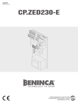
Beninca CPJ3M Owner's manual

Category
Gate Opener
Type
Owner's manual

Beninca CPJ3M is a control unit for automating gates and garage doors, providing secure and convenient access control. With its built-in radio receiver, you can operate the automation system using remote controls, enhancing ease of use. The automatic closing feature ensures the gate closes securely after a set time, adding to the safety of your property. Additionally, the high traffic function allows for uninterrupted operation in busy environments, making it ideal for commercial or residential applications.

Beninca CPJ3M is a control unit for automating gates and garage doors, providing secure and convenient access control. With its built-in radio receiver, you can operate the automation system using remote controls, enhancing ease of use. The automatic closing feature ensures the gate closes securely after a set time, adding to the safety of your property. Additionally, the high traffic function allows for uninterrupted operation in busy environments, making it ideal for commercial or residential applications.

L8542381
02/2013 rev 4
UNIONE NAZIONALE COSTRUTTORI
AUTOMATISMI PER CANCELLI, PORTE
SERRANDE ED AFFINI
CP.J3M
2
COM
P.P.
PHOT
STOP
SHIELD
ANT
ANT
24Vac
1A max
AMPC AMPO TCA
F1
S1
DL1
JP4
2AF
1234
LAMP
24Vac/15Wmax
20
24
35
28
0
20
SERVICE LIGHT
24Vac/10W
230Vac
50Hz
N L
P.P
PGM
CL
ENCODER
JP7
JP1
1 2 5 6 7 8
14151617
18192021
M
ON
F2:1.25AT (230V)
F2:2.5AT (115V)
CP.J3M
3
AMPC AMPO TCA
S1
DL1
JP4
1234
P.P
PGM
CL
1 2 5 6 7 8
14151617
18192021
ON
F1
F10A
+
2 4 s c
V M s c
V M t r s
2 4 t r s
0 t r s
0 s c
-
1 2 V1 2 V
JM.CB
D L1D L2
20
24
35
28
0
20
F2:1.25AT (230V)
F2:2.5AT (115V)
24Vdc
(-) (+)
230Vac
50Hz
N L
Collegamento scheda JM.CB (opzionale) / Connection to the JM.CB Card (optional)
Anschluss Karte JM.CB (option) / Branchement fiche JM.CB (optionnel)
Conexión tarjeta JM.CB (opcional) / Połączenie karty JM.CB (opcjonalna)
9
WARNINGS
This manual has been especially written to be use by quali-
fied fitters.
None of the information provide in this manual can be con-
sidered as being of interest for the end users.
Preserve this manual for future needs.
The technician has to furnish all the information related to the
step by step function, the manual and the emergency function
of the operator, and to deliver the manual to the final user.
;
Foresee on the supply net an onnipolar switch or
selector with distance of the contacts equal or
superior to 3 mms.
Verify that of the electrical system there is an awry differential
interrupter and overcurrent protection.
Some typologies of installation require the connection of the
shutter to be link at a conductive mass of the ground accord-
ing to the regulations in force.
The electrical installation and the operating logic must comply
with the regulations in force.
The leads fed with different voltages must be physically
separate, or they must be suitably insulated with additional
insulation of at least 1 mm.
The leads must be secured with an additional fixture near
the terminals.
During installation, maintenance and repair, interrupt the
power supply before opening the lid to access the electri-
cal parts
Check all the connections again before switching on the
power.
The unused N.C. inputs must be bridged.
The descriptions and the present illustrations in this manual
are not binding. Leaving the essential characteristics of the
product unchanged, the manufacturer reserves himself the
right to bring any change of technical, constructive or com-
mercial character without undertaking himself to update the
present publication.
CE Declaration of Conformity
Declaration in accordance with Directives 2004/108/CE (EMC); 2006/95/CE (LVD)
The Manufacturer:
AUTOMATISMI BENINCÀ SPA
Address:
Via Capitello, 45 - 36066 Sandrigo (VI) - Italy
Declares that the product:
Control box for 1 motor
CP.J3M
conforms with the requirements of the following EU Directives:
DIRECTIVE 2004/108/CE OF THE EUROPEAN PARLIAMENT AND COUNCIL, 15 December
2004, in relation to the harmonisation of the legislation of member states regarding electromagnetic
compatibility, in abrogation of Directive 89/336/CEE, per the following harmonised standards:
EN 61000-6-2:2005, EN 61000-6-3:2007.
DIRECTIVE 2006/95/CE OF THE EUROPEAN PARLIAMENT AND COUNCIL, 12 December
2006, in relation to the harmonisation of the legislation of member states regarding electrical material
intended to be used within certain voltage ranges, per the following harmonised standards:
EN 60335-1:2002 + A1:2004 + A11:2004 + A12:2006 + A2:2006 + A13:2008; EN 60335-1-103:2003.
as applicable:
DIRECTIVE 1999/5/CE OF THE EUROPEAN PARLIAMENT AND COUNCIL, 9 March 1999 in
relation to radio equipment and telecommunications terminals and the mutual recognition of their
conformity, per the following harmonised standards:
ETSI EN 301 489-3 V1.4.1 (2002) + ETSI EN 301 489-1 V1.4.1 (2002) + ETSI EN 300 220-3 V1.1.1
(2000) + EN 60950-1 (2001)
Benincà Luigi, Legal representative.
Sandrigo, 08/07/2008.
10
Control units CP.J3M
INPUT/OUTPUT FUNCTIONS
Terminals Function Description
(1-2) Antenna
Optional antenna connection to built-in radio receiver board (1-
signal/2-screen).
If external antenna connected cut wire welded to “ANT”.
5 COM Common for all control inputs.
6 Step by Step Step by step button input (N.O. contact)
7 STOP STOP button input (N.C. contact)
8 PHOT
Input for safety devices, N.C. contact (e.g. photocells)
In close cycle: if the contact opens, the motor will stop and will in-
stantly reverse direction (opening).
In open cycle: disabled.
JP1/JP7
24VDC Motor
Encoder
IExtractable connector with connection to 24VDC + Encoder
A: + Encoder
B: S Encoder signal
C: - Encoder
14-15 Blinker Blinker connection, 24Vac/15W max.
16-17 24 Vac
Accessory power supply 24Vac/1A max.
IMPORTANT: If the battery charger board JM.CB is installed, the
output (without mains power connected) has a 24Vdc polarised
voltage. Make sure the devices are correctly connected.
(i.e. 16:+24Vdc - 17:-24Vdc).
JP4 Secondary
Secondary circuit of the transformer.
18 Grey: 0V output
19 Red: Slowdown speed.
Connect the Faston to the 20V output
20 Brown: 24V output
21 White: Motor speed.
See section “Motor speed adjustment ”
J3 Radio Receiver Built-in radio receiver
N.B.: To control the automation during installation, the Step by Step button on the control unit can be
used.
TECHNICAL DATA
Contol unit supply
24 Vdc
Power supply
230 Vac 50/60 Hz
Output supply
1 motor 24Vdc
Power maximum motor
120 W
Output supply accessories
24Vdc 1 A max.
Protection level
IP54
Operating temp.
-20°C / +70°C
Radio receiver
The control unit is fitted with a built-in radio module for receiving remote
controls both with fixed codes and variable codes with a frequency of
433.92MHz.
11
Trimmer functions
TCA Adjustment of the automatic close time if enabled by Dip-Switch 1.
Adjustment ranges from 1 sec to max 90 sec
AMP-O Adjustment of the amperometric sensor obstacle detection sensitivity during the open
cycle.
AMP-C Adjustment of the amperometric sensor obstacle detection sensitivity during the close
cycle.
Turn the trimmers clockwise (+) to increase the torque, turn them anticlockwise (-) to reduce
the torque.
Adjustment of trimmers AMP-O and AMP-C must comply with statutory regulations.
If an obstacle is detected:
When opening, the gate is stopped.
When closing, the gate stops and opens for about 3 sec.
Dip-Switch functions
DIP 1 “TCA” Enables or disables automatic closing.
Off: automatic closing disabled
On: automatic closing enabled
DIP 2 “COND.” Enables or disables the high traffic function.
Off: High traffic function disabled.
On: High traffic function enabled. The P.P. (Step-by-step) or transmitter signal is
ignored during the open cycle and the TCA cycle (if enabled).
DIP 3 Not used.
DIP 4 “Radio” Enables or disables transmitters with programmable codes
On: Radio receiver enabled exclusively for rolling-code transmitters.
Off: Receiver enabled for both rolling-code and programmable transmitters
(self-learn and dip-switch) .
Motor speed adjustment
CAUTION! This adjustment strongly affects the safety of the gate automation.
Make sure that the gate thrust complies with statutory regulations.
If the gate speed is changed the amperometric sensor must be calibrated accordingly.
Two faston terminals are provided on the transformer:
Faston F1 (white) regulates the door opening and closing speed and can be preset on three voltage
values:
t 7MPXTQFFE
t 7NFEJVNTQFFE
t 7IJHITQFFE
Faston F2 (red) must not be moved from 20V position.
Configuration with built-in receiver
The control unit is fitted with a built-in radio module for receiving remote controls both with fixed codes
and variable codes (see dip-switch 4 functions), with a frequency of 433.92MHz.
For a transmitter to be used, the module rst has to self-learn its code. The memorise procedure is
illustrated below, the module can memorise up to 64 different codes.
How to memorize a new transmitter code with activation through a P.P. (Step-by-Step) function
- Press the PGM key once for 1 sec, the DL1 LED starts flashing with 1sec intervals.
- Within 10 seconds, press the transmitter key to be stored in memory through the P.P. function. After
storage, the receiver automatically exits the programming mode.
To exit the programming mode without storing the transmitter code into memory, wait for 10 seconds.
Remote learning of a transmitter code (rolling-code only)
If a transmitter code is already memorised, other codes can be stored without accessing the control unit.
The remote storage must be carried out with totally open door, regardless of the TCA setting.
12
Proceed as follows:
1 Press the hidden key of the already memorized transmitter, the courtesy light switches off.
2 Within 10 sec., press the key of the already memorized transmitter, the function of which is to be
copied. The courtesy light and the DL1 LED switch up.
3 Within 10 seconds, press the hidden key of the new transmitter, the function of which is to be matched.
The courtesy light and the DL 1 LED start flashing (1 flashing/sec).
4 Within 10 seconds, press the key of the transmitter to which the function, selected at point 2, is to be
matched. The courtesy light and the DL1 LED switch up for 1 sec.
5 The new transmitter is stored in memory, the receiver exits the programming mode.
Example: the P.P. function, which is to be matched to key 2 of the new “B” TX, is stored on key 1 of
“A” TX. Press in sequence:
hidden key of A TX >> key 1 of A TX >> hidden key of B TX >>key 2 of B TX
Cancelling all transmitters from the memory
- Keep the PGM key pressed for 15 sec, the DL1 LED and the courtesy light start flashing rapidly and
switch off at completion of cancellation.
- Release the PGM key and the memory is now erased.
N.B.:
For safety reasons, transmitters cannot be memorised during the open/close cycles of the motor.
When entering the memorise transmitter procedure, if the Power LED gives a prolonged blink and then
goes out, this signals that the receiver memory is full and no other transmitters can be memorised or that
the transmitter is not compatible.
Storage in memory of the opening and closing positions
After carrying out the electric connections of the control unit and the safety, control and indication devices,
the door opening and closing positions must be memorized.
First of all place the opening and closing mechanical stoppers in the correct position:
- manually release the door and completely close it. Place the closing mechanical stopper in the closed
position on the driving carrier and fix it.
- completely open the door. Place the opening mechanical stopper in the open position on the driving
carrier and fix it.
For further information, please refer to the Manual for use supplied with the operator.
Now the opening and closing positions can be stored in memory:
- with door stopped, press keys PGM+CL for about 5 seconds until the LED DL1 switches on
- the control unit is now ready to store the closing position in memory
- press and keep the CL key pressed until the carrier reaches the CLOSING mechanical stopper. Release
the CL key and press the PGM key for 1 second. The LED switches on and off and the position is therefore
stored in the control unit memory.
- press and keep the PP key pressed until the carrier reaches the OPENING mechanical stopper. Release
the PP key and press the PGM key for 1 second. The LED switches off and the position is therefore stored
in the control unit memory.
Tensioning of the belt
Once the closing mechanical stopper is reached, a brief opening reversion command is given to avert that
the belt remains tensioned.
This reversion movement can be adjusted (or excluded), if required, as follows:
- Press the PGM key once for 1 sec, the courtesy light and the DL1 LED starts flashing with 1sec intervals.
- Press the PGM key again and keep it pressed until the courtesy light and the DL1 LED switch on.
- Release the PGM key and the DL1 LED starts flashing (from 1 to 4 flashes), followed by an interval.
- The number of flashes can be modified by pressing the P.P. key, select the value amongst the following:
1 FLASH with interval: disabled reversion
2 FLASHES with interval: minimum reversion
3 FLASHES with interval: medium reversion (default presetting)
4 FLASHES with interval: maximum reversion
- Confirm the selection by pressing the PGM key, or wait for 10 seconds.
Carry out some trial operations to check the correct operation of the system.
13
Self-diagnosis of the control unit
In normal operating mode, the status of the control unit is displayed as follows:
- LED DL1 off: motor moving or motor stopped without alarm
- 3 flashes of LED DL1 with 1 sec interflash interval: photocell input engaged for more than 5 sec
- 4 flashes of LED DL1 and the courtesy light*, with 1 sec. interval: the amperometric sensor triggers.
- 5 flashes of DL1 LED, and the courtesy light*, with 1 sec. interval: the encoder does not work correctly.
- 7 flashes of LED DL1 and the courtesy light*, with 1 sec. interval: P.P. input is engaged for more than 5
sec.
* The courtesy light indicates its malfunction for around 30 sec. Then, it will switch off.
The LED DL1 continues to indicate the alarm condition until the fault is solved.
Power failure
When a power failure occurs, either in the completely open or in the completely closed positions, at reset of
power the control unit returns to normal operating mode. If a power failure occurs when the door is moving
open or closed, the door relay starts from the intermediate position. During opening, the door will stop
thanks to the activation of the amperometric sensor as soon as the driving carrier reaches the mechanical
stopper.
The normal operating mode of the system will be reset in the following operation.
AUTOMATISMI BENINCÀ SpA - Via Capitello, 45 - 36066 Sandrigo (VI) - Tel. 0444 751030 r.a. - Fax 0444 759728
  • Page 1 1
  • Page 2 2
  • Page 3 3
  • Page 4 4
  • Page 5 5
  • Page 6 6
  • Page 7 7
  • Page 8 8
  • Page 9 9

Beninca CPJ3M Owner's manual

Category
Gate Opener
Type
Owner's manual

Beninca CPJ3M is a control unit for automating gates and garage doors, providing secure and convenient access control. With its built-in radio receiver, you can operate the automation system using remote controls, enhancing ease of use. The automatic closing feature ensures the gate closes securely after a set time, adding to the safety of your property. Additionally, the high traffic function allows for uninterrupted operation in busy environments, making it ideal for commercial or residential applications.

Ask a question and I''ll find the answer in the document

Finding information in a document is now easier with AI