LG YCNB036AAB0 User manual

Category
Electric kettles
Type
User manual

This manual is also suitable for

P/NO : MFL39192001
MSZEF0032
www.lg.com
INSTALLATION MANUAL
AIR CONDITIONER
Please read this installation manual completely before installing the product.
Installation work must be performed in accordance with the national wiring
standards by authorized personnel only.
Please retain this installation manual for future reference after reading it
thoroughly.
TYPE : LG Decorative Type Fan Coil Unit
ITALIANO
2 Fan Coil Unit
Fan Coil Unit Installation Manual
TABLE OF CONTENTS
FOR YOUR RECORDS
Write the model and serial numbers here:
Model #
Serial #
You can find them on a label on the side of each unit.
Dealer's Name
Date Purchased
Staple your receipt to this page in the event you need it
to prove date of purchase or for warranty issues.
READ THIS MANUAL
Inside you will find many helpful hints on how to use and
maintain your air conditioner properly. Just a little
preventive care on your part can save you a great deal
of time and money over the life of your air conditioner.
You'll find many answers to common problems in the
chart of troubleshooting tips. If you review our chart of
Troubleshooting Tips first, you may not need to call for
service at all.
PRECAUTION
• Contact the installer for installation of this unit.
• The unit is not intended for use by young children or
invalids without supervision.
• Young children should be supervised to ensure that
they do not play with the unit.
• When the power cord is to be replaced, replacement
work shall be performed by authorized personnel only
using only genuine replacement parts.
Installation work must be performed in accordance
with the National Electric Code by qualified and
authorized personnel only.
Safety Precautions.................3
Care and maintenance...........8
Before you call for service ..10
Installation ............................11
Installation Manual 3
Safety Precautions
Safety Precautions
To prevent injury to the user or other people and property damage, the following instructions
must be followed.
Incorrect operation due to ignoring instruction will cause harm or damage. The seriousness is
classified by the following indications.
Meanings of symbol s used in this manual are as shown below.
WARNING
CAUTION
This symbol indicates the possibility of death or serious injury.
This symbol indicates the possibility of injury or damage.
Be sure not to do.
Be sure to follow the instruction.
WARNING
Installation
Do not use a defective or
underrated circuit breaker.
Use this appliance on a
dedicated circuit.
There is risk of fire or electric
shock.
For electrical work, contact
the dealer, seller, a qualified
electrician, or an Authorized
Service Center.
Do not disassemble or repair the
product. There is risk of fire or
electric shock.
Always ground the product.
There is risk of fire or electric
shock.
Always install a dedicated
circuit and breaker.
Improper wiring or installation
may cause fire or electric shock
Use the correctly rated
breaker or fuse.
There is risk of fire or electric
shock.
Do not modify or extend the
power cable.
There is risk of fire or electric
shock.
4 Fan Coil Unit
Do not store or use flammable
gas or combustibles near the
product.
There is risk of fire or failure of
product.
Do not use the product in a
tightly closed space for a
long time.
Oxygen deficiency could occur.
When flammable gas leaks, turn off
the gas and open a window for
ventilation before turn the product on.
Do not use the telephone or turn
switches on or off.
There is risk of explosion or fire
Gasolin
Safety Precautions
Operation
Do not install, remove, or
re-install the unit by yourself
(customer).
There is risk of fire, electric
shock, explosion, or injury.
Be cautious when unpacking
and installing the product.
Sharp edges could cause injury.
Be especially careful of the case
edges and the fins on the
evaporator.
For installation, always
contact the dealer or an
Authorized Service Center.
There is risk of fire, electric
shock, explosion, or injury.
Do not plug or unplug the
power supply plug during
operation.
There is risk of fire or electric
shock.
Do not touch(operate) the
product with wet hands.
There is risk of fire or electrical
shock.
Do not place a heater or
other appliances near the
power cable.
There is risk of fire and electric
shock.
Do not let the unit run for a long
time when the humidity is very high
and a door or a window is left open
.
Moisture may condense and wet
or damage furniture.
Take care to ensure that power
cable could not be pulled out or
damaged during operation.
There is risk of fire or electric
shock.
Do not place anything on the
power cable.
There is risk of fire or electric
shock.
Installation Manual 5
Safety Precautions
If strange sounds, or small
or smoke comes from
product. Turn the breaker off
or disconnect the power
supply cable.
There is risk of electric shock or
fire.
Stop operation and close the
window in storm or cyclone.
If possible, remove the
product from the window
before the cyclone arrives.
There is risk of property damage,
failure of product, or electric shock.
When the product is soaked
(flooded or submerged),
contact an Authorized
Service Center.
There is risk of fire or electric
shock.
Be cautious that water could
not enter the product.
There is risk of fire, electric shock,
or product damage.
Ventilate the product from
time to time when operating
it together with a stove, etc.
There is risk of fire or electric
shock.
Turn the main power off
when cleaning or
maintaining the product.
There is risk of electric shock.
When the product is not be used for a long
time, disconnect the power supply plug or
turn off the breaker.
There is risk of product damage or failure, or
unintended operation.
After installing, the water
leakage test should be
perfrmed.
• A bad connection may cause
water leakage.
Install the drain hose to
ensure that water is drained
away properly.
• A bad connection may cause
water leakage.
Keep level even when
installing the product.
• To avoid vibration or water
leakage.
90 °
Safety Precautions
6 Fan Coil Unit
Installation
CAUTION
Operation
Use two or more people to lift and transport
the product.
• Avoid personal injury.
Do not install the product where it will be
exposed to sea wind (salt spray) directly.
• It may cause corrosion on the product. Corrosion,
particularly on the condenser and evaporator fins,
could cause product malfunction or inefficient
operation.
Do not expose the skin
directly to cool air for long
periods of time.
(Don't sit in the draft.)
• This could harm to your health.
Do not use the product for
special purposes, such as
preserving foods, works of
art, etc. It is a consumer air
conditioner, not a precision
refrigeration system.
• There is risk of damage or
loss of property.
Do not block the inlet or
outlet of air flow.
• It may cause product failure.
Safety Precautions
Installation Manual 7
Use a soft cloth to clean. Do
not use harsh detergents,
solvents, etc.
There is risk of fire, electric shock,
or damage to the plastic parts of
the product.
Do not touch the metal parts
of the product when
removing the air filter. They
are very sharp!
There is risk of personal injury.
Always insert the filter
securely. Clea n the filter
every two weeks or more
often if necessary.
A dirty filter reduces the efficiency
of the air conditioner and could
cause product malfunction or
damage.
W
ax
Thinner
Do not insert hands or other
objects through the air inlet
or outlet while the product is
operated.
There are sharp and movin g parts
that could cause personal injury.
Do not drink the water
drained from the product.
It is not sanitary and could cause
serious health issues.
Use a firm stool or ladder
when cleaning or
maintaining the product.
Be careful and avoid personal
injury.
Care and maintenance
8 Fan Coil Unit
B
e
n
z
e
n
e
S
C
O
U
R
I
N
G
C
L
B
A
R
G
E
R
S
I
N
N
E
R
UnitFan coil
Turn the system off before cleaning. To clean,
wipe with a soft, dry cloth. Do not use bleach or
abrasives.
Note:
Supply power must be disconnected before
cleaning the unit.
Never use any of the followings:
Water hotter than 40 ° C
Could cause deformation and/or
discoloration.
Volatile substances
Could damage the surfaces
of the air conditioner.
Clean the filter with a vacuum or warm, soapy
water.
• If very dirty, wash with a solution of
detergent in lukewarm water.
After washing with water, dry well in the shade.
Re-install the air filter.
Air Filter
1
2
3
Care and maintenance
Air filters
Air outlet vent
Caution: Before performing any maintenance,turn off the main power to the system.
The air filters (the suction side) should
be checked and cleaned once every 2
weeks or more often if necessary.
Care and maintenance
Installation Manual 9
1
2
Helpful information
The air filters and your electiric bill.
If the air filters become clogged with dust, the
cooling capacity will drop, and 6% of the
electricity used to operate the air conditioner will
be wasted.
When it is not going to be used for
a long time.
When the unit is to be used again.
Operate the unit on Air circulation mode for
2 to 3 hours.
¥This will dry out the internal parts.
CAUTION:
Turn off the circuit
breaker when the air conditioner is not
goingtobeusedforalongtime.
Dirt may collect and may cause a fire.
Check that the air inlet and outlet of the
unit are not blocked.
Do not overcool the room.
This is not good for the health
and wastes electricity.
Keep blinds or curtains
closed.
Do not let direct sunshine
enter the room when the unit
is in operation.
Make sure that the doors
and windows are shut tight.
Avoid opening doors and
windows as much as possible
to keep the cool air in the
room.
Clean the air filter regularly.
Blockages in the air filter
reduce the airflow and lower
cooling and dehumidifying
effects. Clean at least once
every two weeks.
Ventilate the room
occasionally.
Since windows are kept
closed, it is a good idea to
open them and ventilate the
room now and then.
Turn off the circuit breaker.
Whentheunitisnotgoingtobeusedforalongtime.
Operation Tips
Before you call for service...
10 Fan Coil Unit
Check the following points before requesting repairs or service.... If the malfunction persist, please contact your
dealer.
The unit does not operate.
The room has a peculiar odor.
Does not cool or heat effectively.
4
4, 5, 7
Has the fuse blown or has the circuit breaker
been tripped?
Check that this is not a damp smell exuded by
the walls, carpet, furniture or cloth items in the
room.
Is the air filter dirty? See air filter cleaning
instructions.
The room may have been very hot when the
unit was first turned on. Allow time for it to cool
down.
Are the indoor unit's air inlet or outlet vents
obstructed?
Case Explanation See page
Before you call for service...
Troubleshooting Tips! Save time and money!
Installation
Installation Manual 11
Installation
Selection of the best location
1. Do not have any heat or steam near the unit.
2. Select a place where there are no obstacles
in front of the unit.
3. Make sure that condensation drainage can be
conveniently routed away.
4. Do not install near a doorway.
5. Ensure that the interval between a wall and
the left (or right) of the unit is more than
70cm.
6. Use a stud finder to locate studs to prevent
unnecessary damage to the wall.
Ceiling Suspended
More than
70cm
More than
70cm
More than
30cm
ENGLISH
Installation Manual 7
Install the air conditioner in the location that satisfies the follow-
ing conditions.
• The place shall easily bear a load exceeding four times the
indoor unit’s weight.
• Sufficient space should be available to inspect the unit as in
the figure shown on the right.
• The place where the unit is installed shall be leveled.
• The place shall be suitable for easy connection of the water
• The place where the unit is installed should not be affected
by electrical noise.
• The place where air circulation in the room will be good .
• There should not be any heat source or steam near the unit
20 or
more
100 or
more
100 or
more
175 or
more
Front side
Base
Air flow
direction
Air inlet
direction
1000 or
more
Floor Stand
Window
pipe.
12
Installation
Remove Front Panel
Install Leg Base (For floor standing type)
1.Remove screws both left and right from
the lid as shown in figure 1 .
2.Open the lid,then you can find another 4
screws(both left and right).
3.Remove screws from the front panel
(both left and right)
4.Remove the front panel carefully
To assembly,perform the procedure
in opposite order.
According to the picture, install the Leg Base
(Both left and right).
Preparing Work for Installation
Leg Base
Leg Base
(Accessory)
(Accessory)
Fan Coil Unit
1
2
3
4
Installation Manual 13
Installation
MOUNTING THE ANCHOR NUT AND
BOLT
Prepare 4 suspension bolts. (Each bolts
length should be same.)
Measure and mark the position for the
Suspension bolts and the piping hole.
Drill the hole for anchor nut on the ceiling.
Insert the nuts and washer onto the
suspension bolts for locking the suspension
bolts on the ceiling.
Mount the suspension bolts to the anchor-
nuts firmly.
Secure the hangers onto the Suspension
bolts (adjust level roughly.) using nuts,
washers and spring washers.
Adjust a level with a level gauge on the
direction of left-right, back-forth by adjusting
suspension bolts.
Adjust a level on the direction of top-bottom
by adjusting supension bolts. Then the unit
will be declined to the bottomside so as to
drain well.
:
Tighten the nut and bolt to prevent unit
falling.
DIM.
MODEL
A B
A
B
Washer
Nut
Suspension
bolts
Ceiling
Anchor nut
Suspension
bolts
Spring
washer
Max.
12mm
Hangen
Washer
Nut
036
046
066
086/106
1022
1322
221
221
221
221
126 1622 221
672
822
Hang the Fan Coil unit on suspension bolt as per following guidelines:
1. Lift the fan coil unit to sufficient height.
2. Insert the suspended part of four suspension bolt in the four hangers provided on the side of
main body one by one.
3. Lower the fan coil unit till the hangers rest on their respective flat washer.
4. Adjust the level in the top down direction by adjusting the suspension bolts.
Inclined the fan coil unit as per direction provided in the fig
Installation
1. Install declination of the fan coil unit is very important for the drain of the
decorative type air conditioner.
2. Minimum thickness of the insulation for the connecting pipe shall be 10mm.
3. If the Installation Plates are fixed to horizontal line, the fan coil unit after installing will
be declined to the bottomside.
Front of view
The unit must be horizontal or inclined at angle.
The inclination should be less than or equal to 1 or in between 10 to 20mm inclined in drain
direction as shown in fig.
The unit must be declined to the bottomside of the unit when finished installation.
Side of view
: Installation Information For Declination
Drain hose
10~20mm
Ceiling
Ceiling
10~20mm
Ceiling
5~10mm
Fan coil unit installation
°
14
Fan Coil Unit
Installation Manual 15
Installation
Pipe Connect, Insulation
Water pipe Connection and Insulation
All thermal insulation must comply with local requirement the thickness min 20mm.
Make sure that there is no clearance here.
Overlap with thermal
insulator for piping.
Thermal insulator for water pipe
(Local supply)
Thermal insulator for
piping(Local supply)
Hose clip for thermal insulator(Local supply)
Union for water pipe
Water valve
insulator(Local supply)
Elbow pipe
(Local supply)
Use a spanner to tignten the water pipe. Make sure, the pipe is
tightened firmly
Drainage hole Make sure to be closed
Unit
Drainage pipe
(Local supply)
Thermal insulator
(Local supply)
Ceiling Suspended
Lay the drain hose with a downward inclination so water will drain out.
Always lay the drain with downward inclination
(1/50 to 1/100).
Prevent any upward flow or reverse flow in any
part.
10mm or thicker formed thermal insulator shall
always be provided for the drain pipe.
INCORRECT
CORRECT
Drain piping work
Clip
(Local supply)
Drain pipe
Ceiling Suspended 1/2"
Floor Standing 3/4"
Fan Coil Unit
Installation
Floor Standing
16
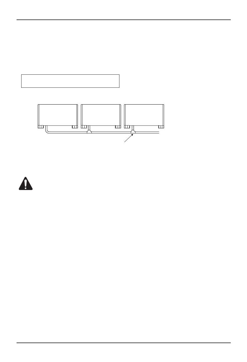
• Drain piping must have downward (1/50 to 1/100): be sure not to provide up-and-down slope to prevent reverse
flow.
• During drain piping connection, be careful not to exert extra force on the drain port on the fan coil unit.
• The outside diameter of the drain connection on the unit is 20mm.
• Be sure to install heat insulation on the drain piping
• If converging multiple dranin pipes, install according to the procedure shown below.
• After piping work is finished check drainage flows smothly.
• Be sure to insulate all indoor units.
Heat insulation material: Polyethylene foam with
thickness more than 10 mm.
Slope downwards at a gradient
of at least 1/100
CAUTION:
Prepare the wiring as follows:
1) Never fail to have an individual power specialized for the unit. As for the method of wiring, be guided by the
circuit diagram pasted on the side panel.
2) Provide a circuit breaker switch between power source and the unit.
3) The screw which fasten the wiring in the casing of electrical fittings are liable to come loose from vibrations to
which the unit is subjected during the course of transportation. Check them and make sure that they are all
tightly fastened. (If they are loose, it could give rise to burn-out of the wires.)
4) Specification of power source
5) Confirm that electrical capacity is sufficient.
6) Be sure that the starting voltage is maintained at more than 90 percent of the rated voltage marked on the name
plate.
7) Confirm that the cable thickness is as specified in the power sources specification.
(Particularly note the relation between cable length and thickness.)
8) Never fail to equip a leakage breaker where it is wet or moist.
9) The following troubles would be caused by voltage drop-down.
• Vibration of a magnetic switch, damage on the contact point there of, fuse breaking, disturbance to the normal
function of a overload protection device.
Installation Manual
Installation
Connecting Cable to the Fan Coil Unit
Connect the wires to the terminals on the control board individually according to the thermostat.
Ensure that the color of the wires of unit and the terminal No. are the same as those of unit respectively.
17
The power cord connected to the unit should be
complied with the following specifications (Rubber
insulation, type H05RN-F approved by HAR or SAA).
If the supply cord is damaged, it must be replaced by a special cord or assembly availible from the manufacturer of its service agent.
CAUTION
mm02
LY/NG
NORMAL CROSS-SECTIONAL
AREA 1.0 mm
2
Install Power Cord
T/B Cover
CAUTION:
Make sure that the screws of the terminal fixed tightly.
Installation
Three step controller Installation (Ceiling Suspend)
Install the 3-step about 5ft(1.5m) above the floor.
Do not install the controller where it can be affected by:
- Drafts, or dead spots behind doors and in corners.
- Concealed pipes and chimneys.
- Uncontrolled areas such as an outside wall behind the controller.
(The standard height is 1.2~1.5 m from floor level.)
5feet
(1.5meters)
no
yes
OFF
OFF
MED
LO
HI
AIR CONDITIONER
OFF
OFF
MED
LO
HI
AIR CONDITIONER
For Floor stand Type, the 3-step controller installed on the unit. If water pipe is on left side, the
controller is on right side, othervise, the controler is on left side. Please open the lid (left or right)
then you can find the controller.
H
I
M
ED
L
O
OF
F
OF
F
A
I
R
C
ON
D
I
T
I
ON
E
R
Floor Standing Type
Fan Coil Unit
18
Installation Manual 19
Installation
To check the drainage.
1. Pour a glass of water on the evaporator using
a kettle.
2. Ensure the water flows through the drain
hose of the indoor unit without any leakage
and goes out the drain exit.
Index
PH[25°C] 6.5~8.0
O O
Electric cOnductivity[25°C](µs/cm) Below 800
O O
ChlOride iOn(mgCl-/L) Below 200
O
Sulfate iOn (mgSO
4
2-
/L) Below 200
O
Acid cOnsumptiOn[PH4.8](mgCaCO
3
/L) Below 100
O
Calcium hardness(mgCaCO
3
/L) Below 150
O
Turbidity Below 20
O O
Fe(mgFe/L) Below 1.0
O O
AmmOnium iOn(mgNH4+/L) Below 1.0
O
IOnic phases silica(mgSiO
2
/L) Below 50
O
SaturatiOn index 0.0~1.0
O O
Item Standards
The influence of water quality
Corrosion
The formation of scale
Standard
Item
Reference
Item
Water Quality
The standards for cooling water quality
Checking the Drainage
Installation
Water Quality
The standards for adding water quality
Index
PH[25°C] 6.5~8.0
Electric conductivity[25°C](µs/cm) Below 200
Chloride ion(mgCl-/L) Below 50
Sulfate ion (mgSO4
2-
/L) Below 50
Acid consumption[PH4.8](mgCaCO3/L) Below 50
Calcium hardness(mgCaCO3/L) Below 50
Turbidity Below 50
Fe(mgFe/L) Below 50
Ammonium ion(mgNH4
+
/L) Below 50
Ionic phases silica(mgSiO2/L) Below 50
Item Standards
Standard Item
Reference Item
Air
Conditioner
Main power source
Circuit Breaker
Use a circuit breake
or time delay fuse.
Fan Coil Unit
20
  • Page 1 1
  • Page 2 2
  • Page 3 3
  • Page 4 4
  • Page 5 5
  • Page 6 6
  • Page 7 7
  • Page 8 8
  • Page 9 9
  • Page 10 10
  • Page 11 11
  • Page 12 12
  • Page 13 13
  • Page 14 14
  • Page 15 15
  • Page 16 16
  • Page 17 17
  • Page 18 18
  • Page 19 19
  • Page 20 20
  • Page 21 21

LG YCNB036AAB0 User manual

Category
Electric kettles
Type
User manual
This manual is also suitable for

Ask a question and I''ll find the answer in the document

Finding information in a document is now easier with AI