Esoteric D-01 User manual
- Category
- Supplementary music equipment
- Type
- User manual
This manual is also suitable for

Monaural D/A Converter
for Super Audio CD and CD
Owner’s Manual
D
-
01

2
CAUTION
<
DO NOT REMOVE THE EXTERNAL CASES OR CABINETS TO
EXPOSE THE ELECTRONICS. NO USER SERVICEABLE PARTS
ARE WITHIN!
<
IF YOU ARE EXPERIENCING PROBLEMS WITH THIS PRODUCT,
CONTACT TEAC FOR A SERVICE REFERRAL. DO NOT USE THE
PRODUCT UNTIL IT HAS BEEN REPAIRED.
WARNING: TO PREVENT FIRE OR SHOCK
HAZARD, DO NOT EXPOSE THIS APPLIANCE
TO RAIN OR MOISTURE.
This equipment has been tested and found to comply with the
limits for a Class B digital device, pursuant to Part 15 of the
FCC Rules. These limits are designed to provide reasonable
protection against harmful interference in a residential
installation. This equipment generates, uses, and can radiate
radio frequency energy and, if not installed and used in
accordance with the instructions, may cause harmful
interference to radio communications. However, there is no
guarantee that interference will not occur in a particular
installation. If this equipment does cause harmful interference
to radio or television reception, which can be determined by
turning the equipment off and on, the user is encouraged to
try to correct the interference by one or more of the following
measures:
• Reorient or relocate the equipment and/or the receiving
antenna.
• Increase the separation between the equipment and
receiver.
• Connect the equipment into an outlet on a circuit different
from that to which the receiver is connected.
• Consult the dealer or an experienced electronic technician
for help.
CAUTION
Changes or modifications to this equipments not expressly
approved by TEAC CORPORATION for compliance will void the
user’s warranty.
For U.S.A.
CAUTION
Ensure this product is not exposed to dripping or splashing
and that no object filled with liquids, such as vases, is placed
on the product.
Do not install this equipment in a confined space such as a
book case or similar unit. Allow adequate air circulation
around this product.
IMPORTANT SAFETY INSTRUCTIONS
1) Read these instructions.
2) Keep these instructions.
3) Heed all warnings.
4) Follow all instructions.
5) Do not use this apparatus near water.
6) Clean only with dry cloth.
7) Do not block any ventilation openings. Install in accordance with
the manufacturer’s instructions.
8) Do not install near any heat sources such as radiators, heat
registers, stoves, or other apparatus (including amplifiers) that
produce heat.
9) Do not defeat the safety purpose of the polarized or grounding-
type plug. A polarized plug has two blades with one wider than
the other. A grounding type plug has two blades and a third
grounding prong. The wide blade or the third prong are provided
for your safety. If the provided plug does not fit into your outlet,
consult an electrician for replacement of the obsolete outlet.
10) Protect the power cord from being walked on or pinched
particularly at plugs, convenience receptacles, and the point
where they exit from the apparatus.
11) Only use attachments/accessories specified by the manufacturer.
12) Use only with the cart, stand, tripod,
bracket, or table specified by the
manufacturer, or sold with the apparatus.
When a cart is used, use caution when
moving the cart/apparatus combination to
avoid injury from tip-over.
13) Unplug this apparatus during lightning storms or when unused
for long periods of time.
14) Refer all servicing to qualified service personnel. Servicing is
required when the apparatus has been damaged in any way,
such as power-supply cord or plug is damaged, liquid has been
spilled or objects have fallen into the apparatus, the apparatus
has been exposed to rain or moisture, does not operate normally,
or has been dropped.
<
Do not expose this apparatus to drips or splashes.
< Do not place any objects filled with liquids, such as vases, on the
apparatus.
<
Do not install this apparatus in a confined space such as a book
case or similar unit.
<
The apparatus draws nominal non-operating power from the AC
outlet with its POWER switch in the off position.
<
The apparatus should be located close enough to the AC outlet
so that you can easily grasp the power cord plug at any time.
<
An apparatus with Class
!
construction shall be connected to an
AC outlet with a protective grounding connection.
CAUTION: TO REDUCE THE RISK OF ELECTRIC SHOCK,
DO NOT REMOVE COVER (OR BACK). NO USER-
SERVICEABLE PARTS INSIDE. REFER SERVICING TO
QUALIFIED SERVICE PERSONNEL.
The lightning flash with arrowhead symbol, within an
equilateral triangle, is intended to alert the user to the
presence of uninsulated dangerous voltage within the
product’s enclosure that may be of sufficient magnitude
to constitute a risk of electric shock.
The exclamation point within an equilateral triangle is
intended to alert the user to the presence of important
operating and maintenance (servicing) instructions in the
literature accompanying this device.

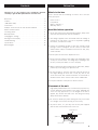
3
Contents
Thank you for choosing Esoteric. Read this manual
carefully to get the best performance from this unit.
Before Use . . . . . . . . . . . . . . . . . . . . . . . . . . . . . . . . . . . . . . . . 3
Features . . . . . . . . . . . . . . . . . . . . . . . . . . . . . . . . . . . . . . . . . . 4
i.LINK (IEEE 1394) . . . . . . . . . . . . . . . . . . . . . . . . . . . . . . . . . . . 5
Connections . . . . . . . . . . . . . . . . . . . . . . . . . . . . . . . . . . . . . . . 6
Example: Connection to the P-01 and the G-0/G-0s . . . . . . . . . 8
Names of Each Control . . . . . . . . . . . . . . . . . . . . . . . . . . . . . . . 9
First Thing To Do. . . . . . . . . . . . . . . . . . . . . . . . . . . . . . . . . . . 11
Basic Operation. . . . . . . . . . . . . . . . . . . . . . . . . . . . . . . . . . . . 11
Changing the Settings . . . . . . . . . . . . . . . . . . . . . . . . . . . . . . 12
Messages on the Display. . . . . . . . . . . . . . . . . . . . . . . . . . . . . 14
Troubleshooting . . . . . . . . . . . . . . . . . . . . . . . . . . . . . . . . . . . 14
Specifications . . . . . . . . . . . . . . . . . . . . . . . . . . . . . . . . . . . . . 15
Block Diagram . . . . . . . . . . . . . . . . . . . . . . . . . . . . . . . . . . . . 16
Before Use
Read this before operation
< As the unit may become warm during operation, always leave
sufficient space around the unit for ventilation.
< The voltage supplied to the unit should match the voltage as
printed on the rear panel. If you are in any doubt regarding
this matter, consult an electrician.
<
Choose the installation location of your unit carefully. Avoid
placing it in direct sunlight or close to a source of heat. Also
avoid locations subject to vibrations and excessive dust, heat,
cold or moisture.
<
Do not place the unit on the amplifier/receiver.
<
Do not open the cabinet as this might result in damage to the
circuitry or electrical shock. If a foreign object should get into
the unit, contact your dealer or service company.
<
When removing the power plug from the wall outlet, always
pull directly on the plug, never yank the cord.
< Do not attempt to clean the unit with chemical solvents as
this might damage the finish. Use a clean, dry cloth. A soft
cloth moistened with a diluted amount of household or
window cleaner can be used to remove more stubborn dirt.
<
Keep this manual in a safe place for future reference.
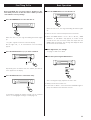
Pin-point foot
Bottom plate
of the unit
Steel foot
Cover foot retaining screws
Cover foot
Chassis
What’s in the box
Please confirm that the following accessories are in the box
when you open it.
Power cord x 1
Felt pads x 4
Owner’s manual x 1
Warranty card x 1
Placement of the unit
High-quality hardened tool steel is used for the pin-point feet,
securely attached to the bottom of the player. Although the
cover feet may appear loose, as the weight of the unit is
applied, they become firm and secure. This design effectively
damps and reduces vibration.
<
Be careful to avoid injury when moving the unit, on account
of its weight. Get someone to help you if necessary.
< To protect floors, etc. you may stick the felt pads supplied
with the unit to the bottom of the cover feet.

4
Features
The world’s first* mono D/A converter that
realizes the full potential of the Super
Audio CD format
(* as of August, 2004)
Our approach of “improvement in sound quality through
discrete L/R channel transmissions” has evolved into a
completely discrete L/R system having two D-01s, one
handling the left channel, and the other the right channel.
The left and right audio signal paths have nothing at all for
common use, both paths are completely isolated and
identical, creating the highest possible reproduction quality,
non-compromised sound. This system also proves its ability in
reproducing ambience and presence data and recreates
details of the performance environment or a feeling of the
original recording session.
What’s more, because each channel has its own power
supply, the design of this supply can be optimized with ample
headroom, achieving an ideal D/A conversion.
• 2 XLR (ES-LINK), 1 RCA, and 2 IEEE 1394 inputs are provided
• DSD signals from Super Audio CD are fed in through XLR
terminals in an Esoteric-exclusive format, ES-LINK, or through
the IEEE 1394 interface.
• A maximum 192 kHz PCM signal can accepted (both Dual
and Stereo transfers available).
• When stereo or multi-channel signals are fed in, only the
sound of the channel you set as explained in the section,
“Channel Selection”(pages 11 and 13), is selected.
• Three digital filter options are provided: FIR, RDOT, and
FIR+RDOT. The filtered signal is converted up to a maximum
768 kHz and then sent to the multi-bit D-A converter
PCM1704. The DSD signal from Super Audio CD is converted
to 88.2 kHz or 176.4 kHz PCM data before being sent to the
digital filter.
• Equipped with RAM-Link (Refined Asynchronous Memory
Link), using a high-precision crystal oscillator, that when
entering word sync mode, the RAM-Link is automatically
activated and acts to eliminate jitter caused before the first
stage of the DAC.
• For the D/A converter, a combination of as many as eight
PCM1704 multi-bit D-A converters is used for the best
possible S-N ratio and linearity, which makes it possible to
faithfully replicate the ambience and presence of the
performance environment.
• The driver circuitry that sends out D/A converted signals uses
a discrete circuit structure operating on ±42 volt rails with
emphasis on driving force and slew rate, making a significant
contribution to the remarkable sound.
Word Sync enabled - Making Synchronizing
with External Equipment Possible
The word sync feature operates either in “OUT” mode (as a
word clock generator) or in the “IN” mode that allows this
unit to lock to an external word clock. It can lock to 44.1,
88.2, 176.4, 48, 96, 192, 100, 48P, 96P, 192P and 100P
(kHz) inputs/outputs. (“P” represents “4% down mode for
PAL films”.)
Selecting the “Rb IN” mode will select a PLL circuit devoted
solely to synchronizing with a rubidium or other high-
precision clock. The use of ESOTERIC’s rubidium master clock
generator G-0s, will produce the most remarkable listening
experience with a feeling of speed and subtle clarity.
Analog potentiometer allows a direct
connection to a power amplifier
With the built-in analog potentiometer (“VOLUME”),
concern’s over truncating or dropping bits, as used in digital
attenuators, is negated.
Copper wires of 6N purity are used for
primary internal wirings, further enhancing
sound quality
High purity 6N copper wires are used for the supplied AC
power cord and most of the internal wirings that may have
effect on the sound quality, thereby boosting the purity and
resolution for a crisp, textured sound.
For the insulating sheath, polyorefin, non-PVC material, is
used out of environmental considerations as well as sound
quality. PVC is not used for any wiring inside the unit. The
high purity 6N copper cable is developed with the help of
Acro Japan Ltd. as is the case with the Esoteric “MEXCEL”
interconnection cable and high purity 8N copper cable.
Highly rigid chassis is immune to internal
and external vibrations that might degrade
sound quality
Thick aluminum is used on the top, side, bottom panels and
rounded corners in addition to the front panel. The entire
body is supported by Esoteric-exclusive pinpoint feet (patent
pending) made of case-hardened tool steel. Exacting
attention is given to the highly precise mounting of all
mechanical parts, the rigidity of the housing, and the
elimination of sympathetic vibrations. To make double sure,
an 8-mm thick plate is used for the upper cover that is subject
to the sound pressure and vibrations from the speakers.
The front and side panels, constructed of thick brushed
aluminum, and the rounded four corners create a feeling of
dignity and gravitas, fitting only to the top level mono D/A
converter for Super Audio CD/CD.
“Super Audio CD” is a registered trademark.
“DSD” is a registered trademark.

5
i.LINK (IEEE 1394)
The i.LINK format, also known as IEEE 1394, is an international
specification for the transferring of extremely fast data.
This unit is ready for i.LINK (AUDIO).
By connecting an i.LINK (AUDIO)-capable device to the IEEE 1394
(or i.LINK AUDIO) terminal on this unit using an i.LINK cable, you
can transmit Super Audio CD multi-channel signals that could
not be transmitted except in analog format in the past. With
i.LINK AUDIO, Super Audio CD can be transmitted in its original
digital format, in addition to the capability of transmitting 2-ch
linear PCM data and multi-channel compressed audio signals.
If you have multiple i.LINK-capable devices, you can connect
them through other devices to transmit data between them.
With i.LINK, you don’t need to be concerned about the order of
connection and wiring errors and phase issues are virtually
eliminated.
Copyright protection system DTCP
To play back audio sounds recorded on Super Audio CD or DVD
discs using i.LINK, both the player and the D/A converter need to
be ready for the copyright protection system DTCP (Digital
Transmission Content Protection). The D-01 already accepts
DTCP.
Data transfer rate
There are three transfer rates: 100 Mbps (S100), 200 Mbps
(S200), and 400 Mbps (S400). This unit is capable of transferring
data at a maximum 400Mbps.
For connection to an i.LINK-capable device, use a commercially
available S400-compliant 6-pin i.LINK cable.
When connecting multiple i.LINK-capable devices, avoid
connecting a device having slow transfer rate between devices
having high transfer rate since this reduces the transfer rate of
your whole system. Connect devices having high transfer rate
towards the source as far upstream as possible.
NOTES
<
Among the i.LINK formats there are “MPEG-2 TS” for BS
digital source and “DV” for digital video for DVD recorders,
as well as the “i.LINK (AUDIO)” (A&M Protocol). Never
connect devices that are not ready for i.LINK (AUDIO) to this
unit. If you do, this unit and others may get out of order or be
damaged.
<
In the process of data transfer, avoid plugging or unplugging
the i.LINK cables while in use or switch the power on and off.
< Among the i.LINK-capable devices there are some that, if not
turned on, are not capable of relaying data.
< There is a possibility some i.LINK-capable devices will not
respond to this unit’s command.
How to connect multiple i.LINK-capable
devices
Daisy chain connection
You can daisy-chain up to 17 devices including this unit.
Connection in tree structure
If you are using a device having three or more i.LINK connectors,
you may want to get the connection branched out. This way of
connection allows you to connect up to 17 devices including this
unit.
Your system does not work if data is fed back to the output
device. Be careful not to create a loop.
i.LINK-capable
device
i.LINK-capable
device
i.LINK-capable
device
i.LINK-capable
device
i.LINK-capable
device
i.LINK-capable
device
i.LINK-capable
device
i.LINK-capable
device
i.LINK-capable
device
i.LINK-capable
device
i.LINK-capable
device
i.LINK-capable
device
i.LINK cable
i.LINK-capable
device
i.LINK-capable
device
i.LINK-capable
device
The i.LINK interface of this unit is designed in accordance with
the following specifications:
1)IEEE Std 1394a-2000, Standard for a High Performance
Serial Bus
2)Audio and Music Data Transmission Protocol 2.0
This unit is compliant with IEC 60958 bitstream, DVD-Audio,
Super Audio CD in the AM824 sequence adaptation layers of
this protocol.
The i.LINK logo is a trademark of Sony Corporation, registered in the U.S. and other countries.

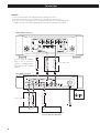
WORD
SYNC
OUT
Amplifier
D-01 (FRONT L channel)
SACD/CD Drive Unit (P-01)
D-01 (other than FRONT L channel)
or a Clock Generator (G-0/G-0s)
AUDIO IN
(FRONT L)
Connect either cable.
Connect either cable.
XLR pin assignment
D
E
C
C A A
BB
6
Connections
CAUTION:
<
Switch off the power to all equipment before making connections.
<
Read the instructions of each component you intend to use with this unit.
<
Be sure to insert each plug securely. To prevent hum and noise, avoid bundling the
signal interconnection cables together with the AC power cord or speaker cables.
Supplied power cord
BNC coaxial cable (75Ω)
BNC coaxial cable (75Ω)
If you are using the G-0/G-0s,
make a direct connection
between its WORD CLOCK
OUT and the P-01’s WORD
SYNC IN.
IEEE 1394 cable
XLR digital cable
XLR cable
RCA cable

7
Digital audio input terminals
Connect any one of these terminals to the digital output
terminal of a digital device (P-01, etc.) using a commercially
available cable.
XLR: Use balanced XLR digital audio cable
COAXIAL: Use RCA (pin) digital audio cable
IEEE1394 / i.LINK (AUDIO):
Use S400 compatible IEEE1394 6pin cable
<
The IEEE 1394 terminal, or i.LINK (AUDIO) terminal, is an
interface that transmits data both ways between the D-01
and an external device. You don’t need to be concerned
with distinguishing between inputs and outputs.
<
The XLR terminal is equipped for Dual AES. If your digital
equipment also is, make the connection between this unit’s
XLR terminal and the corresponding terminal (i.e., the
channel output you want to feed into this unit) on your
digital equipment.
Analog audio output terminals [LINE OUT]
If your amplifier has an audio XLR input, use a commercially
available balanced XLR cable for connection.
If your amplifier has no XLR input, use a commercially
available RCA audio cable.
WORD SYNC input/output terminal
This sends out and receives a sync signal (word).
Connect the WORD SYNC IN to your master clock generator
such as the G-0/G-0s or the word clock output terminal on
the D-01 for an another channel.
Connect the WORD SYNC OUT to the word sync input on
your other digital equipment.
For connection, use a commercially available BNC coaxial
digital cable (75Ω impedance).
SIGNAL GND connection
Use a commercially available insulated stranded wire to
connect the signal ground terminal on the unit to the
amplifier signal ground.
<
Note that this is NOT an electrical safety ground (earth).
D
C
B
A
Power cord receptacle
After all other connections have been made, insert the
supplied AC power cord into this receptacle, then connect
the other end of the power cord into the AC power source.
Ensure that your AC voltage corresponds to the voltage
marked on the rear panel of the unit. Consult a qualified
electrician if you are in doubt.
<
In order to avoid the risk of electric shock, fire, or other
hazard, only use the supplied power cord or a suitably
approved OEM power cord.
<
If you are not going to use the unit for some time,
disconnect the power cord from the wall socket.
E
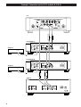
When the P-01 is connected
If the Super Audio CD/CD drive unit, Esoteric P-01, is connected
to the D-01, the following setup will provide you with the best
quality sound:
Setting of the P-01
OUTPUT button “XLR DUAL” or “IEEE1394”
WORD button
“IN” (When the G-0s is connected, “Rb IN”)
UP CONVERT button
“176.4/192”
Setting of the D-01
INPUT button “XLR 1”, “XLR 2” or “IEEE1394”
WORD button One of the D-01 that outputs word
synchronization signals: “OUT”
The others: “IN”
When the G-0s is connected, set all the
D-01 to “IN”.
When the G-0s is connected, set all the
D-01 to “Rb IN”.
W_OUT setting “176.4”
CH_SEL setting respective channels
Setting of the G-0/G-0s
Frequency change button (A, B or C) 176.4kHz
FREQUENCY MODE button 44.1kHz

8
AUDIO IN
(FRONT L)
Amplifier
AUDIO IN
(FRONT R)
Amplifier
D-01 (FRONT L)
D-01 (FRONT R)
G-0/G-0s
P-01
XLR digital cable
BNC coaxial cable
XLR cable
XLR cable
Example: Connection to the P-01 and the G-0/G-0s

9
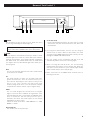
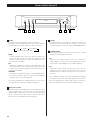
Names of Each Control 1
POWER
Use this button to turn the unit on or off. When the unit is
on, the ring surrounding the button lights up.
A
CBA D FE
Display
The equipment draws nominal non-operating power from
the AC outlet with its POWER switch in the OFF position.
WORD
Use this button to switch between word sync modes. A mode
indicator lights up to show the current mode (blue indicators
showing normal modes, and a purple indicator showing the
4% down mode). The indicator blinks when no usable word
sync signal is detected. No indicator lights when word sync is
not being used.
OUT
Lets the unit internally generate and send out Word Clock
so the unit acts as a master.
IN
This mode provides a stable sync operation with most
general external clocks. There are occasions when sync is
not achieved depending on the output accuracy of the
devices in use. This is because the word clock input
frequency range of this unit is set to as narrow as ±15ppm,
a requirement in order to achieve a sync of high accuracy.
Rb IN
This is a mode designed for external clocks of a higher
degree of precision like a rubidium clock generator. Select
this mode when this unit is connected to the ESOTERIC G-0s.
Keep in mind that it will take time before the sync is
achieved in this mode. This mode requires an even narrow
bandwidth of accuracy to lock.
Switch the mode to IN when “WRD UNLOCK” or “WRD
ERROR!” is shown.
Off (tuned off)
The unit does not use any word sync.
B
4% down mode
Pressing and holding this button for more than 3 seconds
switches the unit back and forth between 4% down and
normal modes.
<
Selecting IN or Rb IN modes achieves sync by using an
external clock as master. When in those modes, the word
clock fed into the WORD SYNC IN terminal is directly sent out
through the WORD SYNC OUT terminal.
<
This unit readily accepts a maximum 196 kHz clock and
automatically switches itself to the incoming signal.
< When selecting IN or Rb IN modes, the corresponding
indicator blinks and searches for an external clock. When the
unit detects a clock and locks to it, the indicator lights steadily
(blue) to show that the unit is ready for play.
<
Make connections to the WORD SYNC terminals prior to
powering on the unit.

10
OUTPUT
This button allows you to adjust the output level in 0.5 dB
steps between –99.5 and +6 dB. You can also set the level to
–∞. When using this feature, switch off the VOLUME BYPASS.
VOLUME BYPASS
Pressing and holding this button for more than 3 seconds
switches the Volume Bypass on and off.
On
By-passes the volume (output level) circuit. Switch the
Volume Bypass on when you will be adjusting the volume
using a connected preamplifier. The indicator lights up.
Off
Switch the Volume Bypass off when this unit is directly
connected to your power amplifier and you will use the
OUTPUT button to adjust the output level. The indicator
turns off.
There is danger a sudden excessively loud signal will damage
the speakers if you switch the Volume Bypass on while in the
process of playing a CD or other media. Be sure to reduce the
preamp’s volume before you switch the Volume Bypass on.
F
E
FILTER
This button selects algorithms for upward conversion.
Pressing the button repeatedly rotates the selection through
the following (a lit indicator shows the current selection):
RDOT
A fluency digital filter that does upward sample rate
conversion. This filter has a slow roll-off characteristic and
provides a smooth immersive sound. A maximum 16 times
up-conversion is available.
FIR
An FIR-type digital filter that does upward sample rate
conversion. This filter has a sharp roll-off characteristic and
provides deep, well-defined sound. A maximum 8 times up-
conversion is available.
FIR+RDOT
This provides a combined function of FIR and RDOT filters.
The two up-conversion filters are directly coupled digitally
so that the best of each is brought out.
Pressing and holding the FILTER button for more than 3
seconds shifts the unit to the setting mode (page 12).
INPUT select switch
Use this switch to select digital inputs. Select which input your
external digital device is connected. The corresponding
indicator lights. It blinks when you select an input to which no
device is connected or a device that is connected but either
turned off or not compatible with the input type.
D
FIR RDOT FIR+RDOT
DF OFF (Digital Filter OFF)
C
Names of Each Control 2
CBA D FE
Display

11
First Thing To Do
Before anything else, you must select a channel for this
unit when you use it for the first time or when you have
reset it back to factory settings.
Press the POWER button to turn the unit on.
1
When the unit is on, the ring surrounding the button lights
up.
“CH_SEL>” appears on the left side of the display.
On the right side, “L R” and channel icons alternately
appear.
Press the OUTPUT button (+/–) to select a channel.
2
Repeatedly press the button until the channel you want to
select appears on the display.
Press the INPUT button to confirm the entry.
3
If you want to change the channel setting, refer to “Channel
Select” in “Changing the Settings” section (page 13).
Basic Operation
Press the POWER button to turn the unit on.
1
When the unit is on, the ring surrounding the button lights
up.
< Also be sure the connected components are turned on.
<
When the WORD button is set to “IN” or “Rb IN”, “WRD
UNLOCK!” or “No Word!” may appear, as it takes several
seconds for the unit to lock the word clock input from the
WORD SYNC IN terminal. The message will disappear when
the unit locks to the word clock.
Make digital filter, etc. settings.
See pages 12 and 13 for details.
Select the input using the INPUT button.
3
2
After selecting the input, play back the source unit.
<
Always turn off the unit after use.
<
If the XLR1 or XLR2 is selected and the XLR DUAL signal is
input, the indicator turns from blue to violet

12
Changing the Settings
Press and hold the FILTER button for more than 3
seconds.
1
The unit enters the setup mode, and “W_OUT>***” appears
on the display. (*** changes depending on the setting.)
The setup mode will be cancelled in the following
instances
• Leave the unit idle for 8 seconds.
• Press and hold the FILTER button for more than 3 seconds
again.
• Press any button other than FILTER or OUTPUT.
Repeatedly press the FILTER button to select a setting to
be changed.
2
For details of each setting, see page 13.
Use the OUTPUT button (+/–) to change the setting.
3
When all the settings are finished, press and hold the
FILTER button for more than 3 seconds (or leave the
unit idle for 8 seconds) to exit the setup mode.
4
< Switching off the power without closing the menu display
may cause problems. Do not turn the unit off.
<
Settings are stored even when power is turned off and the
unit is unplugged. If left unplugged for an extended period,
the settings may be lost.
Restoring factory settings
If you have made a lot of changes in the setup, and want to
restart from a known set of options, restore the unit to the
factory default settings as follows:
1. If the unit is on, press the POWER button to turn it off
Leave the unit for 30 seconds.
2. While holding down the INPUT button, press the POWER
button.
Be sure to keep the INPUT button depressed until the unit is
turned on.
All memories are erased, and the unit returns to the factory
settings.

13
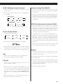
W_OUT (Word sync output frequency)
Select the frequency of the word sync signal. The factory
setting is “44.1k”.
< The word sync signal is output only when the WORD button
is set to “OUT”.
(“P” means “4% down mode for PAL film”)
CH_SEL (Channel Select)
Select the channel for this unit.
<
The icon of the selected channel lights on the display.
<
The icon will blink if the channel you set here differs from the
channel of the input signal. In this case, select the proper
channel again, or check the connection to the digital device.
DSD
Used to select a sampling rate (Fs) to convert DSD to PCM.
88.2 k (factory setting) or 176.4 k are available.
DSD gain
Used to select a level for DSD-PCM conversion. 0 or +6
(factory setting) are available.
<
With the DSD set to 176.4 kHz and the DSD gain to +6, there
is a chance that the sound will be distorted when playing
back discs on which music is recorded at very high volume
levels. If this is the case, set “the DSD to
88.2 kHz and the
DSD gain to +6” or “the DSD to 176.4 kHz and the DSD gain
to
0”.
<
When the DSD gain is set to 0, Super Audio CD discs are
played back at a lower level than CDs are.
L
(Front L)
R
(Front R)
CENTER
LFE
(Subwoofer)
LS
(Left Surround)
RS
(Right Surround)
44.1k
Normal Mode
88.2k 176.4k
96k
48k192k100k
48P(46.08k)
4% Down Mode
96P(92.16k)
100P(96k)
192P(184.32k)
Low-pass analog filter (80kLPF)
The use of this filter produces a subtle difference in sound
directivity. Switch this filter on or off (default) depending on
your preference.
With this filter switched off, there is a chance that unexpected
and abnormal noise could be produced and harm your
speakers or trip the protection circuit on your power amplifier.
To protect your system it is recommended that this filter be
switched ON.
IEEE 1394 remote control function (1394RC)
When multiple D-01 units are directly connected using IEEE
1394 cables and you have this function on, the functions of
all D-01’s in the chain can be controlled using only the left
channel D-01. The P-01 source should be the first machine in
the IEEE 1394 chain followed by all the D-01’s. (Do not
connect the P-01 between the D-01 units.)
The linking of the control functions among the D-01s is
available as long as IEEE 1394 cables are used to connect the
D-01 units. You can use a different input type other than
IEEE 1394 if you chose. If you do use a different input type,
by also connecting the D-01s with IEEE 1394 cables you can
control all D-01s with only one unit as long as this function is
switched on.
With this remote control function switched off, the IEEE 1394
circuit is powered only when the input is set to IEEE 1394.
Dimmer
The display and indicators can be dimmed to suit the
environment in which you listen to music. There are three
levels and an “off” setting.
<
In OFF mode, when you press any button, the illuminations
turn temporarily on.
< Note that the OFF setting is not memorized when the power
is turned off. When the unit is switched off with the display
off, and then turned on again, the display is reset to the
minimum brightness (Dimmer1).
<
The factory setting is “Dimmer3”.

14
Troubleshooting
If you experience any problems with this unit, please take the
time to look through this chart. You may be able to solve the
problem yourself before calling your dealer or technical support.
No power
e
Check the connection to the AC power source. Check and
make sure the AC source is not a switched outlet and that,
if it is, the switch is turned on. Make sure there is power to
the AC outlet by plugging in another item such as a lamp or
fan.
No sound from speakers.
e
Check the connection to the digital device, amplifier and
speakers.
e
If the volume bypass is off, adjust the output level using the
OUTPUT buttons.
The INPUT indicator blinks.
e
Turn on the digital device connected to the input terminal.
e
Check the connection to the digital device. Make sure the
source digital device and the input selection on the D-01 are
the same type.
The safety circuit of the power amplifier is activated.
High-frequency noise from speakers.
e
Set 80kLPF to ON.
Buzzing noise produced at regular intervals.
e
The connected unit may not be in word sync mode while
the D-01 is in word sync mode. Check the word sync
terminal for correct connection and the settings on the
connected unit.
Normally, if this problem occurs, the display reads “WRD
ERROR”, but this message does not appear when deviation
in sync is too small and out of the word error detection
threshold of the D-01.
The WORD indicator blinks.
The display shows “No Word!”
e
The word sync mode is selected, but there is no clock
source. Turn the word sync mode off (see page 9).
e
Invalid word clock is being received. Check cables,
connections, and settings of the clock generator.
The display shows “WRD ERROR!”
e
Invalid word sync signal is received. Check the setting of the
clock generator.
The display shows “WRD UNLCK!”
e
Cannot lock the word sync signal. If “Rb IN” is selected,
select “IN” using the WORD button.
If normal operation cannot be recovered, unplug the
power cord from the outlet and plug it in again. This
resets the internal micro-computer which can be disturbed
during electrical storms, power interruptions, et cetera.
ES-LINK
appears when the ES-LINK compatible Esoteric product is
connected.
No Word!
There is no clock source.
UNKNOWN
The unit connected via the IEEE1394 cable is unknown.
WRD ERROR!
Invalid word sync signal is received.
WRD UNLCK!
Cannot lock the word sync signal.
LOOP ERR!
IEEE1394 connection is looped.
< Normally, “the sampling frequency of an incoming digital
signal” when a CD is played back or “DSD” when an Super
Audio CD is played back are shown on the left of the display.
At the right shows the output level.
<
No output level shows when VOLUME BYPASS is switched on.
<
When detecting a device that is connected with IEEE 1394
cable, the display shows its model name (such as P-01).
Messages on the Display

15
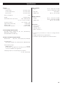
Specifications
General
Power supply
Europe model . . . . . . . . . . . . . . . . . . . . . AC 230 V, 50 Hz
U.S.A./Canada model. . . . . . . . . . . . . . . . AC 120 V, 60 Hz
Korea model . . . . . . . . . . . . . . . . . . . . . . AC 220 V, 60 Hz
Power consumption . . . . . . . . . . . . . . . . . . . . . . . . . . . . 23 W
Weight . . . . . . . . . . . . . . . . . . . . . . . . . . . . 21 kg (46 1/4 lbs)
External dimensions (W x H x D) . . . . . . . 445 x 108 x 420 mm
(17 1/2” x 4 1/4” x 16 9/16”)
Frequency response . . . . . . . . . . . . . . . . 2 Hz - 80 kHz, –3 dB
Signal-to-Noise Ratio (S/N) . . . . . . . . . . . . . . . . 118 dB (JEITA)
Dynamic range . . . . . . . . . . . . . . . . . . . . . . . . . 112 dB (JEITA)
Total harmonic distortion . . . . . . . . . . . . . . . . 0.001% (JEITA)
Valid Sampling Frequency (kHz)
32, 44.1, 88.2, 176.4, 48, 96, 192, 48P(=46.08),
96P(=92.16), 192P(=184.32)
DSD (IEEE1394 or ES-LINK only)
Word Clock Frequency (input/output)
Normal mode . . . . . 44.1, 88.2, 176.4, 48, 96, 192, 100 (kHz)
4% down mode
48P(=46.08), 96P(=92.16), 192P(=184.32), 100P(=96) (kHz)
Input frequency range
WORD IN mode. . . . . . . . . . . . . . . . . . . . . . . . . . ±15 ppm
Rb IN mode is designed for extremely precise external
clocks like a rubidium clock generator.
Sampling frequencies corresponding to de-emphasis
32, 44.1, 48, 96 (kHz)
Input Terminals
Digital . . . . . . . . . . . . . . . . . . . . XLR x2, 5.0Vp-p±0.1V/110Ω
RCA x1, 0.5Vp-p±0.1V/75Ω
IEEE1394 . . . . . . . . . . . . . . . . . . . . . . . . . . . . . . . IEEE1394 x2
WORD SYNC . . . . . . . . . . . . . . . . . . . . BNC x1, TTL level/75Ω
Output Terminals
Analog . . . . . . . . . . . . . . . . . . . RCA x1, 2.2Vrms±0.1V/10kΩ
XLR x1, 2.2Vrms±0.1V/10kΩ
WORD SYNC . . . . . . . . . . . . . . . . . . . . BNC x1, TTL level/75Ω
Accessories
Power cord x 1
Felt pads x 4
Warranty card x 1
Owner
’
s manual x 1
• Design and specifications are subject to change without
notice.
• Weight and dimensions are approximate.
• Illustrations may differ slightly from production models.

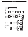
16
Block Diagram
D/A (+)
D/A (+)
D/A (+)
D/A (+)
D/A (
-
)
D/A (
-
)
D/A (
-
)
D/A (
-
)
I/V
I/V
I/V
I/V
Digital
Audio
Interface
Receiver
ES-LINK
Decoder
DSD
q
PCM
Converter
RDOT
Digital
Filter
FIR
Digital
Filter
Master
Clock
X'tal
Word
Clock
Divider
PLL
RAM
LINK
RCA
WORD OUT
WORD IN
XLR1
XLR2
IEEE1394 Interface
IEEE1394
IEEE1394
Highspeed
Isorator
+
+
+
-
+
-
VOLUMEVOLUME
RCA
(
-
)
(+)
XLR
LPFLPF
MCK
VC
-
 1
1
-
 2
2
-
 3
3
-
 4
4
-
 5
5
-
 6
6
-
 7
7
-
 8
8
-
 9
9
-
 10
10
-
 11
11
-
 12
12
-
 13
13
-
 14
14
-
 15
15
-
 16
16


Esoteric D-01 User manual
- Category
- Supplementary music equipment
- Type
- User manual
- This manual is also suitable for
Ask a question and I''ll find the answer in the document
Finding information in a document is now easier with AI
Related papers
Other documents
-
TEAC Esoteric D-05 Owner's manual
-
-
-
-
-
-
-
-
TOA V-01S Specification Data
-
NAD S200 Owner's manual