Magnadyne Silencer SL-42 Installation guide

Category
Car alarm
Type
Installation guide

This manual is also suitable for

Magnadyne Silencer SL-42 is a professional 3-channel, two-way security system designed for expert installation and packed with features to protect your vehicle. It boasts a 5-wire alternating door lock, a 2-step door unlock wire connection, a 4-pin orange connector for a 2-stage shock sensor, a 10-pin accessory connection, a built-in user-programmable timer output, and a (-) 200mA grounded output when armed.

Magnadyne Silencer SL-42 is a professional 3-channel, two-way security system designed for expert installation and packed with features to protect your vehicle. It boasts a 5-wire alternating door lock, a 2-step door unlock wire connection, a 4-pin orange connector for a 2-stage shock sensor, a 10-pin accessory connection, a built-in user-programmable timer output, and a (-) 200mA grounded output when armed.

IM_FULL_SL42_REV_B
PROFESSIONAL SERIES
1
PROFESSIONAL SERIES
INSTALLATION MANUAL
This unit is designed for professional installation only and must be
installed by an authorized Silencer dealer.
Magnadyne Corporation 1111 W. Victoria Street, Compton CA 90220 (800) 340-3200
For Warranty information:
Please visit our website at www.silencer.com
SL- 42
3-Channel
Two-Way Security System
IM_FULL_SL42_REV_B
PROFESSIONAL SERIES
2
INSTALLATION DIAGRAM
IM_FULL_SL42_REV_B
PROFESSIONAL SERIES
3
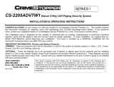
MAIN POWER CONNECTOR
RED / WHITE: PARKING LIGHT RELAY INPUT
WHITE: PARKING LIGHT OUTPUT
BLACK : MAIN SYSTEMS GROUND
BROWN : POSITIVE SIREN OUTPUT
RED : FUSED 12 VOLT (+) BATTERY POWER
5 PIN MAIN POWER WIRE HARNESS:
RED / WHITE WIRE –PARKING LIGHT RELAY INPUT —
The RED/WHITE wire is the input to the ashing parking light relay. The connection of the RED/WHITE wire will determine
the output polarity of the ashing parking light relay.
If the vehicle you are working on has +12volt switched parking lights, you don’t need connect this wire. This wire is
already connected to +12volt.
If the vehicle’s parking lights are ground switched, cut the RED/WHITE wire, connect the RED/WHITE wire to
chassis ground.
WHITE WIRE — PARKING LIGHT RELAY OUTPUT
(+12 V 10A OUTPUT) —
Connect the WHITE wire to the parking light wire coming from the headlight switch. Do not connect the WHITE wire to the
dashboard lighting dimmer switch. (Damage to the dimmer will result). The limitation of the WHITE wire is 10 AMP max.
Do not exceed this limit or damage to the alarm and parking relay will result.
BLACK WIRE — SYSTEM GROUND –
This is the main ground connection of the alarm module. Make this connection to a solid section of the vehicle frame. Do
not connect this wire to any existing ground wires supplied by the factory wire loom, make the connection to the vehicle’s
frame directly.
BROWN WIRE – (+) SIREN OUTPUT –
This wire is provides power to the supplied siren. Connect the Brown wire to the Red wire of the siren. Connect the Black
wire of the siren to a stable chassis ground.
RED WIRE — SYSTEM POWER (+12V CONSTANT) —
The RED wire supplies power to the system. Connect this wire to a stable constant +12 volt source.
4 PIN ANTENNA, LED AND VALET SWITCH CONNECTOR:
The antenna should be mounted to the front windshield of
the vehicle facing down. It should be clear of any metallic
objects or tinting and as close to the center as possible.
The Valet switch and LED are mounted within this unit and
are connected with the ribbon cable.
IM_FULL_SL42_REV_B
PROFESSIONAL SERIES
4
RS232 TWO WAY SERIAL DATA PORT CONNECTION:
This connector is to be used for Serial Data communications with Fortin and ADS/idatalink modules only!
DO NOT CONNECT THIS TO ANY OTHER WIRING!
This port will only operate correctly with Fortin or ADS/idatalink Modules.
3 PIN, DOOR LOCK CONNECTOR ( 500 MA OUTPUT )
1. Blue
Wire
3. Green
Wire
( - ) Lock Pulse
( + ) Unlock Pulse
( - ) Unlock Pulse
(+) Lock Pulse
VACUUM OPERATED DOOR LOCKING SYSTEM:
TYPICAL OF MERCEDES BENZ AND AUDI.
Locate the wire under the driver’s kick panel.
Use the voltmeter connecting to ground, verify
that you have the correct wire with the doors
unlocked, the voltmeter will receive “12 volts”.
Lock the doors and the voltmeter will read
“0 volt”. Move the alligator clip to +12V and
the voltmeter will receive “12 volts”. Cut this
wire and make connections. Be sure to program
door lock timer to 3.5 seconds.
Blue
Wire
( - ) Lock Pulse
( + ) Unlock Pulse
( - ) Unlock Pulse
(+) Lock Pulse
Red(not used)
+12V
Master Door
Lock Switch
X
X
Splice
Splice
Cut the Existing
Lock Wire
To Door
Lock
Motor
To Slave Door
Lock switches
Cut the Existing
Unlock Wire
3 Pin Plug
To Alarm
5-WIRE ALTERNATING DOOR LOCK
30
86
87a
85
87
30
86
87a
85
87
Red +12V
Green Wire
Blue Wire
VACUUM OPERATED CENTRAL LOCKING
Green Wire
Blue Wire
+12V
X
Cut
Compressor
Door Switch
30
86
87a
85
87
30
86
87a
85
87
3 Pin
Plug To
Alarm
NEGATIVE TRIGGER DOOR LOCK SYSTEM
Red (not used)
Blue Wire Door Unlock
Green Wire Door Lock
Locking
Master
Switch
To Exiting
Door Lock Relay
POSITIVE TRIGGER DOOR LOCK SYSTEM
Blue Wire Door lock
Green Wire Door Unlock
Locking
Master
Switch
To Exiting
Door Lock Relay
+ 12V
Red (not used)
2 STEP DOOR UNLOCK WIRE CONNECTION FOR
5 WIRE ALTERNATING DOOR LOCKS
+12V
Cut the Existing
Lock Wire
Cut Existing Unlock
Wire
X
Cut the Unlock Wire
Lock
Unlock
OEM Door Master Lock
Switch
OEM Slave
Door Lock
Switch
+12V
Lock
Unlock
To All Other
Door Lock
Motors
H2/13:
22-Pin
Plug
From
Alarm
Pink Wire
x
X
Blue Wire
OEM Driver’s
Door Lock Motor
+ 12V
85
86
87
87a
30
30
87
85
87a
86
30
87
85
87a
86
Green Wire
H9:
3 Pin
Plug
To
Alarm
Red +12V
2 STEP DOOR UNLOCK WIRE CONNECTION FOR
GROUND SWITCHED DOOR LOCKS
Cut Existing Unlock
Wire
X
Lock
Unlock
OEM Door Master Lock Switch
To All Other
Door Lock
Motors
White/Green
Wire
OEM
Driver's
Door Lock
Motor
Existing Neg.
Lock Wire
Existing Neg.
Unlock Wire
86
30
85
87
87a
+ 12V
Green Wire
Door Lock
Blue Wire
Door Unlock
OEM Door
Lock Relay
H2/13:
22-Pin
Plug
From
Alarm
H9:
3 Pin
Plug
To
Alarm
2 STEP DOOR UNLOCK WIRE CONNECTION FOR
POSITIVE SWITCHED DOOR LOCKS
Cut Existing Unlock
Wire
X
Lock
Unlock
OEM Door Master Lock Switch
To All Other
Door Lock
Motors
White/Green
Wire
OEM Driver's
Door Lock
Motor
+ 12V
Existing Pos.
Lock Wire
Existing Pos.
Unlock Wire
30
87a
87
86
85
+12V
+ 12V
OEM Door
Lock Relay
86
30
85
87
87a
Green Wire
Door Unlock
Blue Wire Door Lock
H2/13:
22-Pin
Plug
From
Alarm
H9:
3 Pin
Plug
To
Alarm
IM_FULL_SL42_REV_B
PROFESSIONAL SERIES
5
4 PIN ORANGE CONNECTOR 2 STAGE SHOCK SENSOR (ZONE 1 / 4)
10 PIN ACCESSORY CONNECTIONS
GREEN WIRE – NEGATIVE DOOR SWITCH SENSING INPUT (ZONE 3) –
This wire is the ground trigger input wire for negative door pin switch. This wire is connection for “grounding” type factory
door pins locate the “common wire” that connects the door pin switches. Make the connection of the GREEN Wire here.
BLACK / BLUE WIRE – (-) 200MA TIMER CONTROL CHANNEL 5
Channel 5 Output (Factory default setting on momentary grounded)
This wire is built-in user-programmable timer output provides a ground through this wire. You may program the built-in
timer to send a ground signal for any time interval between 1 second and 2 minutes. For instance, this timer output may
be used to turn on the headlight with the remote control. Also on certain BMW, Mercedes Benz, Jaguar and Volkswagen
cars, you can use this unique timed output to allow remote closure of all power window and sunroof without the need for
an external module!
YELLOW WIRE - 12 VOLT WITH THE IGNITION ON +
Connect this wire to a 12 Volt source when the ignition of the vehicle is in the ON position.
VIOLET WIRE – POSITIVE DOOR SWITCH SENSING INPUT (ZONE 3)–
This wire is the positive trigger input wire for positive door pin switch. This wire is connection for “positive” type factory
door pins(typical FORD MOTOR). Locate the “common wire” for all door pins and make the connection of the VIOLET
Wire here.
BLUE WIRE – GROUND INSTANT TRIGGER INPUT (ZONE 2) –
This wire is the ground trigger input wire for hood and or trunk pin switches.
1
.
Green
Wire /
Zone 1
Warn Away Input
2. Blue
Wire /
Zone 4
Ground Trigger
3. Black
Wire / Ground
4. Red
Wire / +12Volts
IM_FULL_SL42_REV_B
PROFESSIONAL SERIES
6
ORANGE WIRE – (-) 200MA GROUNDED OUTPUT WHEN ARMED –
This wire will become grounded when the alarm is armed. The current capacity of this wire is 200mA. This output
can control starter disable, when an intrusion is detected and the system is triggered. The vehicles prevent from any
unauthorized starting.
WHITE / BLUE WIRE – (-) 200MA TIMER CONTROL CHANNEL 4
CHANNEL 4 OUTPUT
(Factory default setting on momentary grounded)
This wire is built-in user-programmable timer output provides a ground through this wire. You may program the built-in
timer to send a ground signal for any time interval between 1 second and 2 minutes. For instance, this timer output may
be used to turn on the headlight with the remote control. Also on certain BMW, Mercedes Benz, Jaguar and Volkswagen
cars, you can use this unique timed output to allow remote closure of all power window and sunroof without the need for
an external module!
PINK WIRE – (-) 200MA 2 STEPS UNLOCK OUTPUT
(Factory default setting) (See Alarm Feature Programming)
The 2 steps unlock feature will work for the most fully electronic door lock circuit. The vehicle must have an electronic door
lock switch (not the lock knob or key switch), which locks and unlocks all of vehicle’s doors. When wired for this feature,
press the disarm (or unlock) button one time will disarm the alarm and unlock the driver’s door only. If, press disarm (or
unlock) button two times within 3 seconds, the alarm will disarm and all doors will unlock.
BROWN / WHITE WIRE WIRE – (-) 200MA PROGRAMMABLE OUTPUT HORN OUTPUT –
DOME LIGHT CONTROL
This wire is provided to use the existing
vehicle’s horn as the alarm system’s
optional warning audible device. It’s a
transistorized low current output, and
should only be connected to the low
current ground output from the vehicle’s
horn switch. When the system is
triggered, the horn will sound.
87
87a
85
30
86
IN4003 Diode
H2/15: Orange wire
from control module
“Start”
“On”
Purple wire
X
Cut
Yello wire
White wire
“Acc”
“Off”
Starter
Red wire to
Ignition Switch
85
86
87
87a
30
Brown White
wire
To horn
+ 12 V
+12V Or Ground
Depending On System
Requirements
FUSE
IM_FULL_SL42_REV_B
PROFESSIONAL SERIES
7
DOME LIGHT CONTROL OUTPUT:
This wire becomes grounded when the
dome light controls circuit active. The
current capacity of this wire is 200mA.
This wire can control the operation of
the interior lights. An optional 10 Amps
relay can be used to this system for
interior lights operation.
a). Upon disarming, the interior lights will remain on for 30 seconds.
b). If the alarm is triggered, the interior light will ash for the same duration as the siren
GRAY WIRE – (-) 200MA CHANNEL 3 (TRUNK) OUTPUT –
This will become a 1 second pulse ground by activate (button 3) on transmitter for two seconds, the current capacity
of this wire is 200 mA. This feature allows you to remote control trunk release or other electric device. (Relay may
be required).
TRANSMITTER PROGRAMMING
Enter:
1. Turn the Ignition ‘switch ‘OFF/ON’ 3 TIMES and stay in ON position. Within 15 seconds.
2. Push the Valet switch 3 times and hold in on the 3rd push, when a long chirp is heard then release the valet
switch. You are now in the Transmitter programming mode.
Program:
1. Press any button on transmitter 1 until the siren responds with a conrming chirp; the rst transmitter is
now programmed.
2. Press any button on the second transmitter until the siren responds with a conrming chirp; the second transmitter
is now programmed.
3. Apply the same procedure to program 3rd and 4th transmitters.
Exit: Turn Ignition to ‘OFF’ position, or leave it for 15 seconds. 3 long chirps and 3 parking light ashes will
conrm exit. Note: If more than 4 transmitters programmed, the system will only keep the last four.
87a
86
87
30
85
Fuse
White Wire
+12V
Door
Switch
Courtesy
Light
IM_FULL_SL42_REV_B
PROFESSIONAL SERIES
8
ALARM FEATURE “A” PROGRAMMING:
1. Turn the Ignition ‘switch ‘ON/OFF’ 3 TIMES and stay in OFF position.
2. Push the Valet switch 3 times and hold in on the 3rd push, when a long chirp is heard.
Then release the valet switch. You are now in the Alarm feature A’ programming mode.
Press the transmitter button corresponding to the feature you want to program.
The factory default settings is always [1] LED ash, [1] chirp.
Depress the transmitter button again to change the feature. Simply keep pressing the
transmitter button again until the module advances to your desired setting.
Press
Transmitter
Button
One Chirp /LED one
pulse Factory Default
Setting
Two Chirps /
LED two pulses
Three Chirps /LED
three pulses
Four Chirps /
LED four pulses
1
Active arming Passive arming without
passive door locking
Passive arming with
passive door locking.
2
45 seconds delay
Door Ajar error chirp
Instant Door Ajar error
chirp
3
All Conrmation
chirps on
Siren Conrmation chirp
on only
Horn Conrmation
chirp on only
All Conrmation
chirps off
4
Brown/White wire=
Horn output
Brown/White wire =
Dome light output
5
+
Automatic Rearm off Automatic Rearm on
6
+
Without Car-jack
mode
Active Car-jack mode Passive Car-jack mode
Exit: Turn Ignition to the ‘OFF’ position, or leave it for 15 seconds. 3 long chirps and 3 parking Light ashes will
conrm exit.
IM_FULL_SL42_REV_B
PROFESSIONAL SERIES
9
ALARM FEATURE “B” PROGRAMMING:
1 Turn the Ignition ‘switch ‘ON/OFF’ 3 TIMES and stay in OFF position.
2 Push the Valet switch 4 times and hold in on the 4th push, when a long chirp is heard,
3 Then release the valet switch. You are now in the Alarm feature ‘B’ programming mode.
4 Press the transmitter button corresponding to the feature you want to program.
Press
Transmitter
Button
One Chirp / LED one
pulse
Factory Default Setting
Two Chirps / LED
two pulses
Three Chirps / LED
three pulses
Four Chirps / LED
four pulses
1
Pathway Illumination
Feature “off”
Parking light turns
“on” for 30- second
upon an unlock signal
Parking light turns “on”
for 30- second upon
an unlock signal &
10-second upon a lock
signal.
2
Ignition controlled door
locks & unlocks
Ignition controlled
door locks only
Ignition controlled
door unlocks only
Without ignition controlled
door locks & unlocks
3
0.8 second door lock &
unlock
3.5 second door lock
& Unlock
0.8 second Lock,
0.35 second Unlock
0.8 sec. dbl Lock,
0.8 sec. dbl Unlock
Five Chirps = 0.8 second Lock, double 0.8 second. Unlock
Six Chirps = Double 0.8 second Lock, 0.8 second Unlock
Seven Chirps = Door lock with “Comfort Feature”
Eight Chirps = DBI Two-step unlock ( DBI ONLY )**
Nine chirps = DBI Unlock ALL doors ( DBI Only )**
**Select either of these options when using Two Way Data Bus Interface Only.
For use with ADS & Fortin Compatible data modules and/or Telematics Module.
4
Horn chirp Duration
Standard
Horn chirp Duration
50 mS
Horn chirp Duration
30 mS
Horn chirp duration 10 mS
5
+
Button =
Silent Arm/Disarm
Button = channel
4 AUX 1
Exit: Turn Ignition to ‘OFF’ position, or leave it for 15 seconds. 3 long chirps and 3 parking Light will conrm exit
IM_FULL_SL42_REV_B
PROFESSIONAL SERIES
10
ALARM FEATURE “C” PROGRAMMING:
1. Turn the Ignition ‘switch ‘ON/OFF’ 3 TIMES and stay in OFF position.
2. Push the Valet switch 5 times and hold in on the 5th push, when a long chirp is heard,
Then release the valet switch. You are now in the Alarm feature ‘C’ programming mode.
3. Press the transmitter button corresponding to the feature you want to program.
Press
Transmitter
Button
One Chirp /
LED one pulse
Factory Default
Setting
Two Chirps /
LED two pulses
Three Chirps /
LED three pulses
Four Chirps /
LED four pulses
1
Pink Wire =
Two step door
unlock output
Pink Wire =
Factory Security
Disarm Signal Output
Pink Wire =
Start Status Output
(Shock Sensor Bypass
20 SEC)
Pink Wire =
Start Status Output (Shock
Sensor Bypass 20 MIN)
2
Gray Wire Channel
3 Output = Pulsed
output Trunk output
Gray Wire Channel
3 Output = Latched
output
Gray Wire Channel
3 Output = Latched
output and reset with
ignition “on”
Gray Wire Channel
3 Output = Timer
programming (set to any
interval between 1 second
and 2 minutes.)
3 White/Blue Wire
Channel 4 Output =
Pulsed output
White/Blue Wire
Channel 4 Output =
Latched output
White/Blue Wire
Channel 4 Output =
Latched output and
reset with ignition “on”
White/Blue Wire Channel
4 Output = Timer
programming (set to any
interval between 1 second
and 2 minutes.)
4
ADS Data Protocol Fortin data Protocol
5
+
No Function DBI start output on
channel 4
6
+
White/Blue Wire
Channel 5 Output =
Pulsed output
White/Blue Wire
Channel 5 Output =
Latched output
White/Blue Wire
Channel 5 Output =
Latched output and
reset with ignition “on”
White/Blue Wire Channel
5 Output = Timer
programming (set to any
interval between 1 second
and 2 minutes.)
IM_FULL_SL42_REV_B
PROFESSIONAL SERIES
11
CHANNEL 3/4/5 TIMER CONTROL OUTPUT PROGRAMMING:
Enter:
1. Turn the Ignition ‘switch ‘ON/OFF’ 3 TIMES and stay in OFF position.
2. Push the Valet switch 5 times and hold in on the 5th push, when a long chirp is heard, then release the valet switch.
You are now in the Alarm feature ‘C’ programming mode.
TIMER PROGRAM CHANNEL 3/4/5:
1-a. CH3 Press and release the transmitter button 5 times, [4] LED ash, [4] siren/horn chirp to indicate you are in
features “Channel 3 Timer Programming mode”.
1-b. CH4 Press and release the transmitter
button 4 times, [4] LED ash, [4] siren/horn chirp to indicate you are in
features “Channel 4 Timer Programming mode”.
1-c. CH5 Press and release the transmitter
+ button 4 times, [4] LED ash, [4] siren/horn chirp to indicate you are in
features “Channel 5 Timer Programming mode”.
2. Press and hold the valet switch, the timer will immediately start.
3. When the desired interval has passed, release the valet switch. 1 long chirp for conrmation.
(Set to any interval between 1 second and 2 minutes)
Note:
If your built-in timer controls window/sunroof closure in your car DO NOT change the timer setting! This requires installer-
only programming. Changing the value will adversely affect operation and may cause damage.
Latched output = The latched output selection will output a negative signal as soon as the Channel 3, 4 & 5 button is
pressed and will continue until the button is pressed again.
Magnadyne Corporation 1111 W. Victoria Street Compton CA 90220 (800) 340-3200
For Warranty information: Please visit our website at www.silencer.com
  • Page 1 1
  • Page 2 2
  • Page 3 3
  • Page 4 4
  • Page 5 5
  • Page 6 6
  • Page 7 7
  • Page 8 8
  • Page 9 9
  • Page 10 10
  • Page 11 11

Magnadyne Silencer SL-42 Installation guide

Category
Car alarm
Type
Installation guide
This manual is also suitable for

Magnadyne Silencer SL-42 is a professional 3-channel, two-way security system designed for expert installation and packed with features to protect your vehicle. It boasts a 5-wire alternating door lock, a 2-step door unlock wire connection, a 4-pin orange connector for a 2-stage shock sensor, a 10-pin accessory connection, a built-in user-programmable timer output, and a (-) 200mA grounded output when armed.

Ask a question and I''ll find the answer in the document

Finding information in a document is now easier with AI