Page is loading ...

SERIES 7 DUAL CHECK
BACKFLOW PREVENTERS
PRODUCT GUIDE
SERIES 7 DUAL CHECK
BACKFLOW PREVENTERS

2
Center Stem Guide
Limit Stops
Replaceable Seats
Chloramine Resistant
Construction
Edge Guides
Modular
Design
O-Ring Seals
SERIES 7 CHECK MODULE
Model/Series
Features
7 L7 O7S 7B 7C CU7
Center Stem Guides
••••••
Edge Guides
•••••
Chloramine Resistant
••••••
Components
Modular Design
•••••
Limit Stops
••• •
Stainless Steel Springs
••••••
Replaceable Seats
•••••
No Exposed Screws
••••••
Or Threads
Protecting the Public Water Supply
Both public water supply officials and consumers need
to protect the public supply of safe drinking water.As a
public water supply professional, you need to do every-
thing in your power to prevent the reverse flow associat-
ed with:
◆ Main line flushing (maintenance)
◆ Fire
f
ighting (emergency)
◆ Main line rupture or blowout (disaster)
Such activities and occurrences can siphon domestic
water systems, drawing every conceivable fluid connect-
ed to the user’s system back into the public water
supply.
The Series 7 Backflow Preventers provide cost-effective
backflow protection of the public water supply when
used according to the local or state plumbing code
Presenting Series 7 Dual Check Backflow Preventers from Watts
requirements. As part of your comprehensive con-
tainment program, you should require the installation
of a Series 7 unit as a condition for the user to receive
service from the public water system.This three-step
program should ideally include:
The first line of defense
The user certifies that his/her domestic water system
complies with the local plumbing codes.
The second line of defense
The user installs a dual check backflow preventer at
the water meter as prescribed by the supplier of safe
drinking water.
The third line of defense – education
The supplier of water provides educational material that
teaches the user how to avoid contaminating or pollut-
ing the drinking water once it has entered his domestic
water system.
To ensure the safety of drinking water, there can be no room
for compromise.That’s why Watts provides the incomparable
Series 7 Backflow Preventers with dual check security.
Installed at the residential water meter or service entrance,
the Series 7 Backflow Preventers offer:
◆ Low pressure drop.
◆ Easy maintenance and service.
◆ Wide selection of types,sizes, and connections.
Our unique check modules put our Series 7 Backflow
Preventers distinctly ahead of other residential containment
devices.With their innovative design, most Series 7 models
offer a full range of features, including:
◆ Chloramine resistance – for long life under the harshest
water conditions.
◆ Complete modularity – for easy maintenance.
◆ Limit stops – to prevent damage from thermal expansion.
◆ Center and edge guides – to ensure repeatable seating and
minimize localized wear.
◆ No exposed screws or threads – to eliminate corrosion
potential and improve serviceability.
Of course,the Series 7 Dual Check Backflow Preventers
embody the quality engineering of Watts, a world leader in
valve technology.And you have the confidence of knowing the
Series 7 are ASSE 1024 and CSA B64.6 Certified. So when you
need to be sure you have the most reliable residential contain-
ment products,specify the Watts Series 7 backflow preventers.

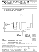
DESCRIPTION
The straight line, poppet-type construction of the Series 7 mini-
mizes pressure drop and provides smooth flow characteristics. It can
be installed horizontally or vertically. It is not adversely affected by
normal line pressure surges, will not cause water hammer, and
operates without chatter or vibration.
STANDARDS
Tested and certified to meet ANSI/ASSE Standard 1024. CSA
Certified to Standard No. B64.6.
Important: Inquire with governing authorities for local installation
requirements.
SPECIFICATIONS
The dual check backflow preventer shall meet the domestic require-
ments of ANSI/ASSE Standard 1024, and bear the seal of approval. It
shall be bronze-bodied and include not less than one union, with
the union nut drilled to accept a tamper-proofing lock wire.A brass
identification tag indicating direction of flow shall be securely
attached to the valve body by corrosion-resistant mechanical fasten-
ers.The dual check shall be Watts Regulator Company’s Series 7.
(Please select the model best suited to your application.)
MATERIALS
Cast bronze body, durable plastic check modules,
injection molded of acetyl resin and PPO, sili-
cone discs and Buna ‘N’ seals, stainless steel
springs, one union and “O” ring union seal.
(
3
⁄4" size also available in brass. See Series 7B p.7)
PRESSURE / TEMPERATURE
Max. pressure: 150 psi (10 bars). Min. pressure:
10 psi (69 kPa).Working temperature: 33°Fto
140°F sustained; intermittent to 180°F (0.6°C to
60°C sustained;intermittent to 82.2°C)
3
SERIES 7
Dual Check Backflow
Preventers
Size:
1
/2" through 1
1
/4" (13-32mm)
Available with an extensive combination of inlet/outlet sizes, types
of thread, and end connections –including retrofit compression fit-
tings and hose connections–the Series 7 can be installed in a variety
of piping configurations, and in conjunction with a wide range of
meter horns, copper setters, and meter boxes.
S
O
U
T
H
E
R
N
B
U
I
L
D
I
N
G
C
O
D
E
C
O
N
G
R
E
S
S
I
N
T
E
R
N
A
T
I
O
N
A
L
1
9
4
0
"THE STANDARD CODES"
1
⁄2"(13mm)
3
⁄4"(19mm)
1",1
1
⁄4"
(25, 32mm )
Residential In-House basement
installation utilizing copper horn
water meter support.
Watts No. 7
Dual Check
3 ft. ±
(.914m±)
PRODUCT AVAILABILITIES
Series 7: Inlet/Outlet Connections – Types available, ordering code, sizes available.
Connection Connection Sizes Available
Type Code inches mm
National Pipe Thread Female 2
1
⁄
2
,
3
⁄
4
, 1 13,19,25
National Pipe Thread Male 3
1
⁄
2
,
3
⁄
4
,1,1
1
⁄
4
13,19,25,31
Meter Thread Female* 4
3
⁄
4
,1,1
1
⁄
4
19,25,31
Meter Thread Male* 5
3
⁄
4
,1,1
1
⁄
4
19,25,31
Pack Joint Female 6
3
⁄
4
, 1 19,25
Pack Joint Male 7
3
⁄
4
, 1 19,25
Female Solder 8
3
⁄
4
, 1 19,25
Male Solder 9
3
⁄
4
, 1 19,25
Female Meter Thread (Swivel) 10
3
⁄
4
,1,1
1
⁄
4
19,25,31
Male Hose Thread 11
3
⁄
4
19
Female Hose Thread 12
3
⁄
4
19
Male Meter Yoke Thread 13
3
⁄
4
19
A
B1
B
ABB
1
Weight
inches mm inches mm inches mm lbs. kgs.
4
3
⁄
8
110 2
5
⁄
16
58 1
3
⁄
4
44 1.75 .79
DIMENSIONS / WEIGHT
bar psi
1.0 15
.84 12
.63 9
.42 6
.21 3
0
5101520253035
gpm
19 38 57 76 95 114 133 lpm
5101520253035gpm
19 38 57 76 95 114 133 lpm
bar psi
1.0 15
0.7 10
0.3 5
0
Flow
* See “How To Order" on pages 10, 11
Union (U) Connections available on all inlet/outlet types and sizes.

4
SERIES L7
In-Line Testable/Serviceable
Dual Check Backflow Preventers
Sizes:
3
⁄4" and 1" (19,25mm)
MATERIALS
Cast bronze body, plastic check assemblies,
silicone discs and stainless steel springs.
PRESSURE / TEMPERATURE
Maximum pressure: 175 psi (12 bars).
Minimum pressure: 10 psi (69 kPa).
Working temperature: 33°F to 140°F sus-
tained; intermittent to 180°F (0.6°C to 60°C
sustained; intermittent to 82.2°C).
*
When ordering No. 7 Valves with Meter
Thread Connections be sure to order the
meter connections one size larger than meter.
Examples:
For
1
⁄
2
"(13mm) and
5
⁄
8
"(16mm) water meter;
order
3
⁄
4
"(19mm) meter thread connection.
For
5
⁄
8
"(16mm) and
3
⁄
4
"(19mm) water meter;
order 1"(25mm)meter thread connection.
For 1"(25mm) water meter; order
1
1
⁄
4
"(32mm) meter thread connection.
PRODUCT AVAILABILITIES
Series L7: Inlet Connections - Types available, ordering code, sizes available
Connection Connection Sizes Available
Type Code inches mm
National Pipe Thread Female 2
3
⁄
4
, 1 19, 25
National Pipe Thread Male 3
3
⁄
4
, 1 19, 25
Meter Thread Female * 4
3
⁄
4
, 1 19, 25
Meter Thread Male * 5
3
⁄
4
, 1 19, 25
Pack Joint Female 6
3
⁄
4
, 1 19, 25
Pack Joint Male 7
3
⁄
4
, 1 19, 25
Female Solder 8
3
⁄
4
, 1 19, 25
Male Solder 9
3
⁄
4
, 1 19, 25
Female Meter Thread (Swivel) 10
3
⁄
4
, 1 19, 25
Male Hose Thread 11
3
⁄
4
, 1 19, 25
Female Hose Thread 12
3
⁄
4
, 1 19, 25
Series L7: Outlet Connections - Types available, ordering code, sizes available
National Pipe Thread Female 2
3
⁄
4
, 1 19, 25
Meter Thread Female 4
3
⁄
4
, 1 19, 25
Female Hose Thread 12
3
⁄
4
19
See
"How To Order" on pages 10 & 11.
Union (U) Connections available on all inlet/outlet types and sizes
Union
Tailpiece
Covers
Cover Seal
O-ring
Tailpiece
Seal O-ring
Disk Assembles
Body
3
⁄4"(19mm)
1"(25mm)
Cover Seal
O-ring
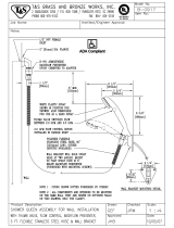
DESCRIPTION
The ideal solution for residential containment applications that
require in-line testable and serviceable dual check backflow preventers.
STANDARDS
Tested and certified to meet ANSI/ASSE
Standard 1024.
Important: Inquire with governing authorities for local installation
requirements.
SPECIFICATIONS
The dual check backflow preventer shall be designed under the ASSE
Standard 1024. It shall be bronze-bodied with top and bottom
guided plastic check assemblies.The dual check shall have three
plugged test ports and shall be capable of being tested in-line. Dual
check shall have two top-mounted covers for in-line service. Check
assembly shall be designed without screws located within the water-
way and shall be fully guided throughout its range of travel. Dual
check shall be Watts Regulator Company’s Series L7. (Please select
the model best suited to your application.)
bar psi
1.0 15
0.7 10
0.3 5
0
51015202530
gpm
19 38 57 76 95 114 lpm
Size A B E F Weight
inches mm inches mm inches mm inches mm inches mm lbs. kgs.
3
⁄
4
19 5
3
⁄
4
146 2
5
⁄
8
67 4
7
⁄
8
124
3
⁄
4
19 2.3 1.0
1255
3
⁄
4
146 2
5
⁄
8
67 4
15
⁄
16
124 1 25 2.3 1.0
E
F
A
B
Flow

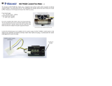
DESCRIPTION
Installed at the residential fire sprinkler service connection to
the main, Series 07S Dual Check Backflow Preventers protect
the water supply against polluted water being siphoned back
from the sprinkler system.
STANDARDS
Tested and certified under ANSI/ASSE Standard 1024, CSA
Certified to Standard No. B64.6, UL Classified file # EX3185,
and complies with NFPA Standard 13D for flow requirements
to residential fire sprinklers. (1" Size only)
Important: Inquire with governing authorities for local instal-
lation requirements.
SPECIFICATION
The dual check backflow preventer shall meet the require-
ments of ANSI/ASSE Standard 1024 and be UL Classified. It
shall be bronze-bodied and feature replaceable seats and sili-
cone seat discs.The springs shall be captured to prevent
injury.The valve shall be capable of flow rate in excess of 50
gpm. Pressure drop at 30 gpm shall not exceed 6 psi.An
identification tag shall be securely attached to the body by
corrosion-resistant mechanical fasteners and a union connec-
tion shall be provided.The dual check shall be Watts Regulator
Company’s No. 07S.
5
SERIES 07S
Residential Fire Sprinkler System
Dual Check Backflow Preventers
Size:1" and 1
1
⁄4" (25,32mm)
MATERIALS
Cast bronze body, durable plastic check modules,
silicone discs and Buna ‘N’ seals, stainless steel
springs, one union and “O” ring union seal.
PRESSURE / TEMPERATURE
Maximum pressure: 175 psi (12 bars).
Minimum pressure: 10 psi (69 kPa).
Working temperature: 33°F to 140°F sustained;
intermittent to 180°F (0.6°C to 60°C sustained;
intermittent to 82.2°C).
Maximum recommended flow: 50 gpm(190 lpm).
PRODUCT AVAILABILITIES
Series 07S: Inlet Connections - Types available, ordering code, sizes available
Connection Connection Sizes Available
Type Code inches mm
Meter Thread Female 4 1, 1
1
⁄
4
25, 32
National Pipe Thread Male 2 1, 1
1
⁄
4
25, 32
Series 07S: Outlet Connections - Types available, ordering code, sizes available
Meter Thread Male 5 1, 1
1
⁄
4
25, 32
National Pipe Thread Male 3 1, 1
1
⁄
4
25, 32
See “How To Order” on pages 10, 11
1",1
1
⁄4"
(25, 32mm)
No. 07S
No. 7
No. 07S No. 7
Potable water
To Fire Sprinklers
Potable water
To Fire Sprinklers
A
B1
B
ABB
1
Weight
inches mm inches mm inches mm lbs. kgs.
6
3
⁄
4
171 2
13
⁄
16
71 2 50 3 1.36
bar psi
1.0 15
0.7 10
0.3 5
0
10 20 30 40 50 60
gpm
38 76 114 152 190 228 lpm
Flow

DESCRIPTION
The straight line, poppet-type construction of the Cu7 minimizes
pressure drop and provides smooth flow characteristics. It can be
installed horizontally or vertically.The copper body of the Series
Cu7 is lead free and is of a time proven durable material.All models
are standardly furnished with double unions for ease of installation
and repair.
STANDARDS
Tested and certified to meet ANSI/ASSE Standard 1024.
SPECIFICATIONS
The dual check backflow preventer shall meet ASSE 1024.The valve
body shall be of copper tube construction and shall be furnished
with double unions to facilitate installation.The check module shall
be of a modular design and shall include limit stops to prevent over
compression or damage to the check valves due to water hammer
or thermal expansion. Each check valve shall be both center and
edge-guided to ensure repeatable seating and minimize localized
wear.The dual check shall be Watts Regulator Company's Series Cu7.
6
SERIES CU7
Copper-bodied Dual Check
Backflow Preventer
Sizes:
1
⁄
2
" through 1" (13-25mm)
MATERIALS
Copper body, corrosion resistant plastic check
modules, silicone discs and Buna ‘N’ seals, stain-
less steel springs.
PRESSURE / TEMPERATURE
Maximum Pressure: 175 psi (12 bars)
Minimum Pressure: 10 psi (69 kPa)
Working Temperature: 33 to 180°F (.6 to 82°C)
continuous.
PRODUCT AVAILABILITIES
Series CU7: Inlet/Outlet Connections - Types available, ordering code, sizes available
Connection Connection Sizes Available
Type Code inches mm
National Pipe Thread Female 2
1
⁄
2
",
3
⁄
4
",1" 13, 19, 25
National Pipe Thread Male 3
1
⁄
2
",
3
⁄
4
",1" 13, 19, 25
Meter Thread Female* 4
3
⁄
4
",1" 19, 25
Meter Thread Male* 5
3
⁄
4
",1" 19, 25
Female Solder 8
3
⁄
4
",1" 19, 25
Female Meter Thread (Swivel) 10
3
⁄
4
",1" 19, 25
See “How to Order”on pages 10,11.
Size A L Weight
in. mm Model in. mm in. mm lbs. kg.
1
⁄2 13 Cu7U2-U2 4
7
⁄16 113 2
11
⁄16 69 1.7 3.7
3
⁄4 19 Cu7U2-U2 4
7
⁄16 113 2
11
⁄16 69 1.7 3.7
1 25 Cu7U2-U2 4
11
⁄16 119 2
11
⁄16 69 2.0 4.4
A
2
11
⁄32
L
1
⁄2"(13mm)
3
⁄4"(19mm)
1"
(25, 32mm )
bar psi
1.0 15
.84 12
.63 9
.42 6
.21 3
0
5101520253035
gpm
19 38 57 76 95 114 133 lpm
5101520253035gpm
19 38 57 76 95 114 133 lpm
bar psi
1.0 15
0.7 10
0.3 5
0

7
DESCRIPTION
Dual Check Series 7B Backflow Preventers feature a similar design
to Series 7 (see page 2), but are constructed of machined brass
rather than bronze.
STANDARDS
Tested to meet or exceed the performance requirements of
ANSI/ASSE Standard 1024 for “Dual Check Valve Type
Backflow Preventers.”
Important: Inquire with governing authorities for local
installation requirements.
SPECIFICATIONS
The dual check backflow preventer shall be installed at the water
meter or service entrance to prevent reverse flow of water into
the potable domestic water system.These devices shall consist of
two independently-acting check valves, internally spring-loaded
and center stem guided to a normally closed position with sili-
cone discs. Designed and constructed to operate under intermit-
tent or continuous pressure conditions.The dual check backflow
preventer shall meet the domestic requirements of ANSI/ASSE
Standard 1024.The dual check shall be Watts Regulator Company
3
⁄4" (19mm) No. 7B.
MODEL 7B
Dual Check Backflow Preventers (Brass)
Size:
3
⁄4" (19mm)
MATERIALS
Machined brass construction, durable plastic check
modules, injection molded of acetyl resin, silicone
discs, Buna ‘N’ seals, and stainless steel springs.
PRESSURE / TEMPERATURE
Maximum pressure: 150 psi (10 bars).
Minimum pressure: 10 psi (69 kPa).
Working temperature: 33°F to 140°F constant;
intermittent to 180°F (0.6°C to 60° C sustained;
intermittent to 82.2° C).
Maximum recommended flow: 15 gpm (57 lpm)
PRODUCT AVAILABILITIES
Series 7B: Inlet Connections – Types available, ordering code, sizes available.
Connection Connection Sizes Available
Type Code inches mm
(U) National Pipe Thread Female 2
3
⁄
4
19
Series 7B: Outlet Connection – Types available, ordering code, sizes available.
National Pipe Thread Female 2
3
⁄
4
19
See “How to Order” on pages 10, 11.
Union (U) Connections available on all inlet/outlet types and sizes.
ABB
1
Weight
inches mm inches mm inches mm lbs. kgs.
4 100 1
1
⁄
2
38 1
1
⁄
4
32 1.7 .49
B1
A
B
No. 7B
3ft. ±
No. 7B
Watts Water Pressure
Reducing Valve
bar psi
112 16
.84 12
.56 8
.28 4
0
2 4 6 81012141618
gpm
7.6 15.2 22.8 30.4 38 45.6 53 60.8 32.4 lpm
Flow

8
SERIES 7/7C
Dual Check Backflow Preventer For
In-Line Continuous Pressure Applications
Size:
3
⁄8" (10mm)
DESCRIPTION
The Dual Check Series 7C is ideally suited for in-line continuous
pressure applications such as wash-down sinks or other applications
in which a hose-type device, connected to the domestic water
supply, can be submerged in a non-potable liquid.
STANDARDS
7C is tested and certified to meet ANSI/ASSE Standard 1024 for “Dual
Check Valve Type Backflow Preventers.” CSA Certified to Standard No.
B64.6.
Important: Inquire with governing authorities for local installation
requirements.
SPECIFICATIONS
A dual check backflow preventer shall be installed at each wash sink
hose unit or at referenced cross-connections to prevent the reverse
flow of non-potable water into the potable domestic water system.
These devices shall be chrome-plated brass consisting of two indepen-
dently acting check valves, internally force-loaded to a normally closed
position and designed and constructed to operate under intermittent
or continuous pressure conditions.The backflow preventer shall be
Watts Regulator Company’s
3
⁄8" (10mm) Series 7C. (Please select the
model best suited to your application.)
MATERIALS
Machined brass construction, chrome nickel
plated body, EPR rubber check disc assemblies
and Buna ‘N’ seals, stainless steel springs and
pressure plates are standard.
PRESSURE / TEMPERATURE
Maximum pressure: 150 psi (10 bars).
Minimum pressure: 10 psi (69 kPa).
Working temperature: 33°F to 140°F constant;
intermittent to 180°F (0.6°C to 60° C sustained;
intermittent to 82.2° C).
Maximum recommended flow: 15gpm (57lpm)
PRODUCT AVAILABILITIES
Series 7C: Inlet Connections – Types available, ordering code, sizes available.
Connection Connection Sizes Available
Type Code inches mm
(U) National Pipe Thread Female 2
3
⁄
8
10
Series 7C: Outlet Connection – Types available, ordering code, sizes available.
National Pipe Thread Female 2
3
⁄
8
10
See “How to Order” on pages 10, 11.
Union (U) Connections available on all inlet/outlet types and sizes.
3
⁄8" No. 7C
Open End, only outlet on fixture.
Cold
Hot
AB
1
Weight
inches mm inches mm oz gm
2
7
⁄
8
73 1
1
⁄
4
32 10 284
A
B1
◆ 7 – Brass
◆ 7C – Brass with chrome nickel plate finish
◆ H7/H7C – With hose connection in brass
or chrome nickel plate
bar psi
10. 15
.84 12
.63 9
.42 6
.21 3
0
12345678910
gpm
3.8 7.6 11.4 15.2 19.0 22.8 26.6 30.4 34.2 38 lpm
Flow

9
Solving Thermal Expansion Problems.
By installing a backflow preventer on any residential water system, you
create a closed system that won’t accommodate thermal expansion.
However,Watts offers several solutions to help you relieve excess pres-
sure due to thermal expansion.
Watts
®
Governor 80 Ball Cock &
Relief Valve
A triple purpose product featuring a toilet tank ball
cock fill valve, anti-siphon backflow preventer, and a
thermal expansion relief valve.
The Governor 80 eliminates the need for expansion
tanks, auxiliary relief valves, and their discharge lines
by governing and limiting the pre-set static pressure in
the domestic water system to 80 psi, as required by plumbing codes.
◆ Maximum operating temperature: 110°F (43°C). ◆ FDA Approved.
◆ Standard heights: 10", 11
1
⁄2", 12
1
⁄2" (250, 292, 318mm). ◆ ASSE 1002.
Series DET Potable Water Expansion Tank
For Domestic Hot Water Systems
An expansion tank designed to absorb the increased
volume of water created when water in a storage tank
is heated. By doing so, the DET keeps the system pres-
sure below the relief setting of the Temperature and
Pressure relief valve.
◆ Pre-pressurized steel tank with expansion membrane
that prevents contact of water and air, ensuring long
life for the system.
◆Thermally-fused epoxy liner.
◆ In-line and free standing models available.
◆ Listed by IAPMO.
◆ Field-adjustable pre-charge.
Series 530 Pressure Relief Valve
Designed to effectively relieve pressure due only to
thermal expansion in a closed system.
Furnished without a lever.
◆ Adjustment Pressure Range:
50-175 psi (3 - 12 bars).
IMPORTANT: On all installations, inquire with governing authorities for local requirements.
Relief Valve
Ball Cock & Relief Valve

Series 7: Inlet/Outlet Connections – Types available, ordering code, sizes available.
Connection Connection Sizes Available
Type Code inches mm
National Pipe Thread Female 2
1
⁄
2
,
3
⁄
4
, 1 13, 19, 25
National Pipe Thread Male 3
1
⁄
2
,
3
⁄
4
,1,1
1
⁄
4
13, 19, 25, 32
Meter Thread Female* 4
3
⁄
4
,1,1
1
⁄
4
19, 25, 32
Meter Thread Male* 5
3
⁄
4
,1,1
1
⁄
4
19, 25, 32
Pack Joint Female 6
3
⁄
4
, 1 19, 25
Pack Joint Male 7
3
⁄
4
, 1 19, 25
Female Solder 8
3
⁄
4
, 1 19, 25
Male Sweat 9
3
⁄
4
, 1 19, 25
Female Meter Thread (Swivel) 10
3
⁄
4
,1,1
1
⁄
4
19, 25, 32
Male Hose Thread 11
3
⁄
4
19
Female Hose Thread 12
3
⁄
4
19
Male Meter Yoke Thread 13
3
⁄
4
19
Union (U) Connections available on all inlet/outlet types and sizes.
Specify Specify “U” if union Specify inlet Specify “U” if union Specify outlet Specify inlet Specify outlet
Series No. inlet is desired connection code outlet is desired connection code connection size connection size
7U 2 U 23⁄4"(19mm) 3⁄4"(19mm)
10
HOW TO ORDER
Watts Dual Check Backflow Preventers can be specified in many different combinations of connection types,
sizes, and union options. See ordering example below.
* When ordering Series 7 Valves with Meter
Thread Connections, be sure to order connection
size one size larger than meter thread. Examples:
Meter Size
Order
1
⁄
2
"(13mm) and
5
⁄
8
"(16mm)
3
⁄
4
" (19mm)
5
⁄
8
"(16mm) and
3
⁄
4
"(19mm) 1"(25mm)
1"(25mm) 1
1
⁄
4
"(32mm)
* When ordering Series L7 Valves with Meter
Thread Connections, be sure to order connection
one size larger than meter thread. Examples:
Meter Size Order
1
⁄
2
"(13mm) and
5
⁄
8
"(16mm)
3
⁄
4
" (19mm)
5
⁄
8
"(16mm) and
3
⁄
4
"(19mm) 1"(25mm)
1"(25mm) 1
1
⁄
4
"(32mm)
7
X
""
L7
U
(N/A)
X
-
X
""
-
-
SERIES 7
SERIES L7
Series L7: Inlet Connections - Types available, ordering code, sizes available
Connection Connection Sizes Available
Type Code inches mm
National Pipe Thread Female 2
3
⁄
4
, 1 19, 25
National Pipe Thread Male 3
3
⁄
4
, 1 19, 25
Meter Thread Female * 4
3
⁄
4
, 1 19, 25
Meter Thread Male * 5
3
⁄
4
, 1 19, 25
Pack Joint Female 6
3
⁄
4
, 1 19, 25
Pack Joint Male 7
3
⁄
4
, 1 19, 25
Female Solder 8
3
⁄
4
, 1 19, 25
Male Solder 9
3
⁄
4
, 1 19, 25
Female Meter Thread (Swivel) 10
3
⁄
4
, 1 19, 25
Male Hose Thread 11
3
⁄
4
, 1 19, 25
Female Hose Thread 12
3
⁄
4
, 1 19, 25
Series L7: Outlet Connections - Types available, ordering code, sizes available
National Pipe Thread Female 2
3
⁄
4
, 1 19, 25
Meter Thread Female 4
3
⁄
4
, 1 19, 25
Female Hose Thread 12
3
⁄
4
19
Union (U) Connections available on all inlet/outlet types and sizes
7U2-2
3
⁄4"(19mm) x
3
⁄4"(19mm) shown
L7U2-2 1"(25mm) x 1"(25mm) shown

11
07S
1
1
/
4
"
(32m)
1
1
/
4
"
(32m)
CU7
U
U
3
/
4
"
3
/
4
"
(19mm)
U2
""
X
-
X
-
7B
X
-
2
2
7/7C
X
-
2
3
/
8
"
(10mm)
3
/
8
"
(10mm)
SERIES 07S
SERIES CU7
MODEL 7B
SERIES 7/7C
Series 07S: Inlet Connections - Types available, ordering code,sizes available
Connection Connection Sizes Available
Type Code inches mm
Meter Thread Female 4 1, 1
1
⁄
4
25, 32
National Pipe Thread Male 2 1, 1
1
⁄
4
25, 32
Series 07S: Outlet Connections - Types available, ordering code,sizes available
Meter Thread Male 5 1, 1
1
⁄
4
25, 32
National Pipe Thread Male 3 1, 1
1
⁄
4
Union (U) Connections available on all inlet/outlet types and sizes
Series 7B: Inlet Connections – Types available, ordering code, sizes available.
Connection Connection Sizes Available
Type Code inches mm
(U) National Pipe Thread Female 2
3
⁄
4
19
Series 7B: Outlet Connection – Types available, ordering code, sizes available.
National Pipe Thread Female 2
3
⁄
4
19
Union (U) Connections available on all inlet/outlet types and sizes.
Union Connections standard on inlet connection.
3
⁄
8
"(10mm) No. H7 or H7C is supplied with
3
⁄
4
" (19mm)
H.T. adapters for
3
⁄
4
" (19mm) H.T. female inlet and
3
⁄
4
"(19mm) H.T. male outlet.
Series 7C: Inlet Connections – Types available, ordering code, sizes available.
Connection Connection Sizes Available
Type Code inches mm
(U) National Pipe Thread Female 2
3
⁄
8
10
Series 7C: Outlet Connection – Types available, ordering code, sizes available.
National Pipe Thread Female 2
3
⁄
8
10
Union (U) Connections available on all inlet/outlet types and sizes.
07SU4-4
1"(25mm) x 1"(25mm) shown
7BU3-3
3
⁄4"(19mm) x
3
⁄4"(19mm)
shown
7U2-2
3
⁄8"(10mm) x
3
⁄8"(10mm) with
3
⁄4"(19mm) HT adapter shown
Series CU7: Inlet/Outlet Connections - Types available, ordering code, sizes available
Connection Connection Sizes Available
Type Code inches mm
National Pipe Thread Female 2
1
⁄
2
",
3
⁄
4
",1" 13, 19, 25
National Pipe Thread Male 3
1
⁄
2
",
3
⁄
4
",1" 13, 19, 25
Meter Thread Female* 4
3
⁄
4
",1" 19, 25
Meter Thread Male* 5
3
⁄
4
",1" 19, 25
Female Solder 8
3
⁄
4
",1" 19, 25
Female Meter Thread (Swivel) 10
3
⁄
4
",1" 19, 25
See “How to Order”on pages 10,11.
CU7
3
⁄4"(19mm) x 1"(25mm)
shown
* When ordering Series CU7 Valves with Meter
Thread Connections, be sure to order connection
one size larger than meter thread. Examples:
Meter Size Order
1
⁄
2
"(13mm) and
5
⁄
8
"(16mm)
3
⁄
4
" (19mm)
5
⁄
8
"(16mm) and
3
⁄
4
"(19mm) 1"(25mm)

Backflow Preventers
Watts Regulator provides a wide variety of backflow preventers for residential and
commercial uses, including:
◆ Reduced Pressure Zone
◆ Reduced Pressure Detector Assemblies
◆ Double Check Valves
◆ Double Check Detector Assemblies
◆ Dual Check Valve Backflow Preventers
Commercial Products
Watts offers a diverse range of commercial products, including:
◆ Gate, Globe & Check Valves
◆ Flow Measurement & Balancing Valves
◆ Ball Valves
◆ Butterfly Valves
◆ Hot Water Extender Tempering Valves
THE BEST IN THE BUSINESS
Automatic Control Valves
Watts delivers a full family of automatic control valves, including:
◆ Pressure Reducing Valves
◆ Pressure Relief and Sustaining Valves
◆ Altitude Valves
◆ Rate of Flow Valves
◆ Flood Protection Valve
For More Information Contact:
◆ Strainers
◆T&P Relief Valves
◆ Pressure Regulators
◆ Wall Hydrants
◆ Water Hammer Arrestors
◆ Intermediate Atmospheric Vent
◆ Atmospheric Vacuum Breakers
◆ Pressure Vacuum Breakers
◆ Hose Connection Vacuum Breaker
◆ Spill Resistant Vacuum Breaker
◆ Backflow Prevention Enclosures
◆ Pump Control Valves
◆ Float Valves
◆ Solenoid Control Valves
◆ Check Valves
© Watts Regulator Co. 1997
USA: 815 Chestnut St., No. Andover, MA 01845-6098; www.wattsreg.com
Canada: 5435 North Service Rd., Burlington, ONT. L7L 5H7; www.wattscda.com
Printed in U.S.A.PG-7 0005
/