Page is loading ...

Latitude 12 Rugged Extreme Tablet – 7212
Owner's Manual
Regulatory Model: T03H
Regulatory Type: T03H002

Notes, cautions, and warnings
NOTE: A NOTE indicates important information that helps you make better use of your product.
CAUTION: A CAUTION indicates either potential damage to hardware or loss of data and tells you how to avoid the problem.
WARNING: A WARNING indicates a potential for property damage, personal injury, or death.
© 2018 Dell Inc. or its subsidiaries. All rights reserved. Dell, EMC, and other trademarks are trademarks of Dell Inc. or its subsidiaries. Other trademarks
may be trademarks of their respective owners.
2018 -02
Rev. A01

Contents
1 Working on your computer............................................................................................................................. 7
Safety instructions............................................................................................................................................................. 7
Before working inside your computer.............................................................................................................................. 7
Turning o your computertablet — Windows 10...........................................................................................................8
After working inside your computer.................................................................................................................................8
2 Removing and installing components............................................................................................................. 9
Recommended tools.......................................................................................................................................................... 9
Screw size list..................................................................................................................................................................... 9
Battery............................................................................................................................................................................... 10
Removing the battery................................................................................................................................................ 10
Removing the battery when the cross strap is attached - Optional.................................................................... 12
Installing the battery...................................................................................................................................................14
Installing the battery when the cross strap is attached - Optional............................................................................ 15
Subscriber Identication Module (SIM) card................................................................................................................ 15
Removing uSIM...........................................................................................................................................................15
Inserting the uSIM...................................................................................................................................................... 16
Display assembly...............................................................................................................................................................16
Removing display assembly....................................................................................................................................... 16
Installing display assembly.........................................................................................................................................20
Stylus..................................................................................................................................................................................21
Removing stylus..........................................................................................................................................................21
Installing stylus............................................................................................................................................................ 21
WLAN card....................................................................................................................................................................... 22
Removing WLAN card...............................................................................................................................................22
Installing WLAN card................................................................................................................................................. 22
WWAN card......................................................................................................................................................................23
Removing WWAN card..............................................................................................................................................23
Installing WWAN card................................................................................................................................................24
CMOS battery.................................................................................................................................................................. 24
Removing CMOS battery..........................................................................................................................................24
Installing CMOS battery............................................................................................................................................25
Power button assembly...................................................................................................................................................26
Removing power button assembly.......................................................................................................................... 26
Installing power button assembly............................................................................................................................. 27
Micro serial port and power connector port.................................................................................................................28
Removing micro serial port and power connector port.........................................................................................28
Installing micro serial port and power connector port...........................................................................................30
Front camera.................................................................................................................................................................... 30
Removing front camera.............................................................................................................................................30
Installing front camera...............................................................................................................................................33
Microphone.......................................................................................................................................................................34
Removing microphone...............................................................................................................................................34
Contents
3

Installing microphone.................................................................................................................................................35
Heat sink for SSD.............................................................................................................................................................36
Removing heatsink for SSD or PCIE....................................................................................................................... 36
Installing heatsink for SSD or PCIE..........................................................................................................................36
PCIe Solid State Drive (SSD)..........................................................................................................................................37
Removing PCIe Solid State Drive - SSD..................................................................................................................37
Installing PCIe Solid State Drive - SSD....................................................................................................................38
System fan........................................................................................................................................................................38
Removing system fan................................................................................................................................................38
Installing system fan.................................................................................................................................................. 39
System Board................................................................................................................................................................... 40
Removing system board............................................................................................................................................40
Installing system board..............................................................................................................................................46
Docking Board.................................................................................................................................................................. 46
Removing docking board...........................................................................................................................................46
Installing docking board............................................................................................................................................. 47
Back Camera.................................................................................................................................................................... 48
Removing back camera.............................................................................................................................................48
Installing back camera............................................................................................................................................... 50
Smartcard holder.............................................................................................................................................................. 51
Removing smartcard holder...................................................................................................................................... 51
Installing smartcard holder........................................................................................................................................53
Bottom base assembly.................................................................................................................................................... 53
Removing bottom base assembly............................................................................................................................ 53
Installing bottom base assembly.............................................................................................................................. 55
3 Technology and components........................................................................................................................57
Power adapter.................................................................................................................................................................. 57
USB features.................................................................................................................................................................... 57
USB 3.0/USB 3.1 Gen 1 (SuperSpeed USB)........................................................................................................... 57
Speed.......................................................................................................................................................................... 58
Applications................................................................................................................................................................ 58
Compatibility...............................................................................................................................................................59
Memory features..............................................................................................................................................................59
4 Software......................................................................................................................................................60
Supported operating systems........................................................................................................................................ 60
Downloading drivers........................................................................................................................................................ 60
Intel audio drivers..............................................................................................................................................................61
Intel chipset drivers.......................................................................................................................................................... 61
Intel HD Graphics drivers.................................................................................................................................................61
Network drivers................................................................................................................................................................62
System devices drivers................................................................................................................................................... 62
Storage drivers.................................................................................................................................................................63
5 System specications..................................................................................................................................64
Product overview.............................................................................................................................................................64
4
Contents

Key Features...............................................................................................................................................................64
Power and battery-status light...................................................................................................................................... 65
System specications......................................................................................................................................................65
Processor specications................................................................................................................................................. 65
Memory specications.................................................................................................................................................... 65
Storage specications.....................................................................................................................................................65
Audio specications.........................................................................................................................................................66
Video specications.........................................................................................................................................................66
Camera specications..................................................................................................................................................... 66
Communication specications........................................................................................................................................67
Port and connector specications................................................................................................................................. 67
Display specications.......................................................................................................................................................67
Touch specications........................................................................................................................................................ 68
Adapter specications.....................................................................................................................................................68
Physical dimension specications..................................................................................................................................69
Environmental specications..........................................................................................................................................69
6 System setup...............................................................................................................................................70
Boot Sequence.................................................................................................................................................................70
Navigation keys................................................................................................................................................................ 70
System Setup overview................................................................................................................................................... 71
General screen options...............................................................................................................................................71
System Conguration screen options......................................................................................................................72
Video screen options..................................................................................................................................................74
Security screen options............................................................................................................................................. 74
Secure Boot................................................................................................................................................................ 76
Intel software Guard Extensions.............................................................................................................................. 76
Performance screen options.....................................................................................................................................77
Power Management...................................................................................................................................................77
POST Behavior...........................................................................................................................................................79
Manageability............................................................................................................................................................. 80
Virtualization Support options..................................................................................................................................80
Wireless options.......................................................................................................................................................... 81
Maintenance................................................................................................................................................................81
System Log..................................................................................................................................................................81
Support Assist System Resolution...........................................................................................................................82
7 Troubleshooting........................................................................................................................................... 83
Dell Enhanced Pre-Boot System Assessment - ePSA diagnostic 3.0....................................................................... 83
Diagnostic LED.................................................................................................................................................................83
General Troubleshooting..................................................................................................................................................84
8 Ecosystem Accessories............................................................................................................................... 86
Active Stylus.....................................................................................................................................................................86
Getting the stylus ready for use.....................................................................................................................................86
Setting the Stylus Mode..................................................................................................................................................87
System base view............................................................................................................................................................ 88
Contents
5

System right view............................................................................................................................................................ 89
Dock front view................................................................................................................................................................89
Keyboard Dock ................................................................................................................................................................90
Turn the Backlight On - O and Adjust Brightness ...............................................................................................91
Keyboard Function - Fn Key Lock ........................................................................................................................... 91
Dock rear view..................................................................................................................................................................92
Input Output module....................................................................................................................................................... 92
Rugged tablet vehicle dock............................................................................................................................................ 93
6 Contents

Working on your computer
Safety instructions
Use the following safety guidelines to protect your computer from potential damage and to ensure your personal safety. Unless otherwise
noted, each procedure included in this document assumes that the following conditions exist:
• You have read the safety information that shipped with your computer.
• A component can be replaced or, if purchased separately, installed by performing the removal procedure in the reverse order.
WARNING: Disconnect all power sources before opening the computer cover or panels. After you nish working inside the
computer, replace all covers, panels, and screws before connecting to the power source.
WARNING: Before working inside your computer, read the safety information that shipped with your computer. For additional
safety best practices information, see the Regulatory Compliance Homepage at www.dell.com/regulatory_compliance
CAUTION: Many repairs may only be done by a certied service technician. You should only perform troubleshooting and simple
repairs as authorized in your product documentation, or as directed by the online or telephone service and support team.
Damage due to servicing that is not authorized by Dell is not covered by your warranty. Read and follow the safety instructions
that came with the product.
CAUTION: To avoid electrostatic discharge, ground yourself by using a wrist grounding strap or by periodically touching an
unpainted metal surface that is grounded to ground yourself before you touch the computer to perform any disassembly tasks.
CAUTION: Handle components and cards with care. Do not touch the components or contacts on a card. Hold a card by its
edges or by its metal mounting bracket. Hold a component such as a processor by its edges, not by its pins.
CAUTION: When you disconnect a cable, pull on its connector or on its pull-tab, not on the cable itself. Some cables have
connectors with locking tabs; if you are disconnecting this type of cable, press in on the locking tabs before you disconnect the
cable. As you pull connectors apart, keep them evenly aligned to avoid bending any connector pins. Also, before you connect a
cable, ensure that both connectors are correctly oriented and aligned.
NOTE: The color of your computer and certain components may appear dierently than shown in this document.
Before working inside your computer
To avoid damaging your computer, perform the following steps before you begin working inside the computer.
1 Ensure that you follow the Safety instruction.
2 Ensure that your work surface is at and clean to prevent the computer cover from being scratched.
3 Turn o your computer.
4 If the computer is connected to a docking device (docked) such as the optional Media Base or Battery Slice, undock it.
CAUTION
: To disconnect a network cable, rst unplug the cable from your computer and then unplug the cable from the
network device.
5 Disconnect all network cables from the computer.
6 Disconnect your computer and all attached devices from their electrical outlets.
7 Turn the computer upside-down on a at work surface.
NOTE
: Ensure to close the display if the system is a laptop. To avoid damaging the system board, remove the main battery
before you service the computer.
8 Remove the main battery.
1
Working on your computer 7
9 Turn the computer top-side up.
NOTE: Open the display if the system is a laptop.
10 Press the power button to ground the system board.
CAUTION: Before touching anything inside your computer, ground yourself by touching an unpainted metal surface, such as
the metal at the back of the computer. While you work, periodically touch an unpainted metal surface to dissipate static
electricity, which could harm internal components.
11
Remove any installed ExpressCards or Smart Cards from the appropriate slots.
Turning o your computertablet — Windows 10
CAUTION: To avoid losing data, save and close all open les and exit all open programs before you turn o your computer or
remove the side cover.
1 Click or tap .
2
Click or tap and then click or tap Shut down.
NOTE: Ensure that the computer and all attached devices are turned o. If your computer and attached devices did not
automatically turn o when you shut down your operating system, press and hold the power button for about 6 seconds to
turn them o.
After working inside your computer
After you complete any replacement procedure, ensure that you connect external devices, cards, and cables before turning on your
computer.
CAUTION
: To avoid damage to the computer, use only the battery designed for this particular Dell computer. Do not use batteries
designed for other Dell computers.
1 Connect any external devices, such as a port replicator or media base, and replace any cards, such as an ExpressCard.
2 Connect any telephone or network cables to your computer.
CAUTION
: To connect a network cable, rst plug the cable into the network device and then plug it into the
computer.
3 Connect your computer and all attached devices to their electrical outlets.
4 Turn on your computer.
8
Working on your computer

Removing and installing components
This section provides detailed information on how to remove or install the components from your computer.
Recommended tools
The procedures in this document require the following tools:
• Phillips #0 screwdriver
• Phillips #1 screwdriver
• Standard DSP plastic scribe
Screw size list
Table 1. Latitude 7212 Rugged Extreme Tablet screw size list
Component M2*2 M2*2.5 M2*3 M2*4 M2*5 M2.5*3 M2.5*5 M2.5*8
Smart card 6
Bottom Base 6 81 19
Front Camera 2
Rear Camera 3
Protective
Rubber
Bumper( all
four corners)
8
WLAN 1
WWAN 1
M.2 SSD 1
System
Board
Assembly
(System
Board and
Fan)
14
Power
Button
Assembly
1
DC-In Cable
and Bracket
3
Kensington
Lock Bracket
3
LCD Bezel 19
Bracket
Docking
1
2
Removing and installing components 9
Battery
Removing the battery
WARNING: Using an incompatible battery may increase the risk of re or explosion. Replace the battery only with a compatible
battery purchased from Dell. The battery is designed to work with your Dell Tablet. Do not use a battery from any other computer
with your tablet.
WARNING: Before removing or replacing the battery, turn o the computer, disconnect the AC adapter from the electrical outlet
and the tablet, and remove any other external cables from the tablet.
1 Follow the procedure in Before Working Inside Your Computer.
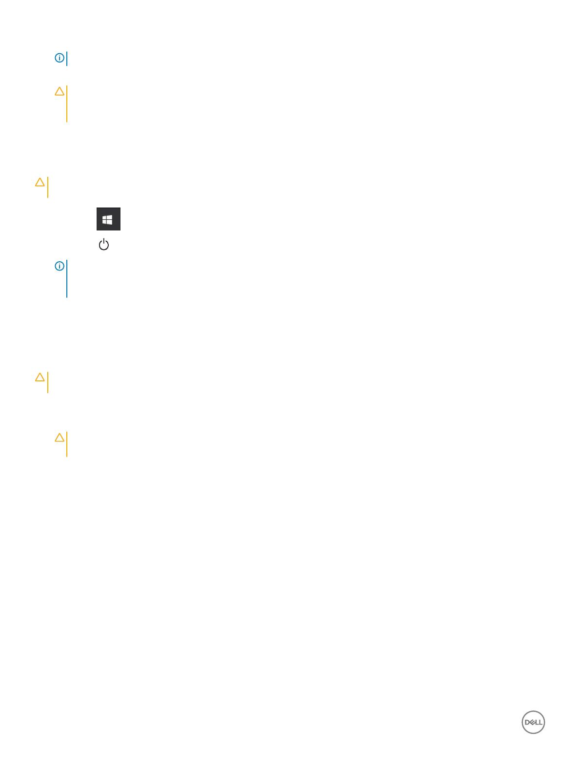
2 Locate the battery and slide the battery latch to unlock the battery release latch [1].
3 Push the button in a downward direction to release the battery [2].
10 Removing and installing components

The battery is released from the battery bay.
4 Lift the edge of the battery that pops up.
Removing and installing components
11

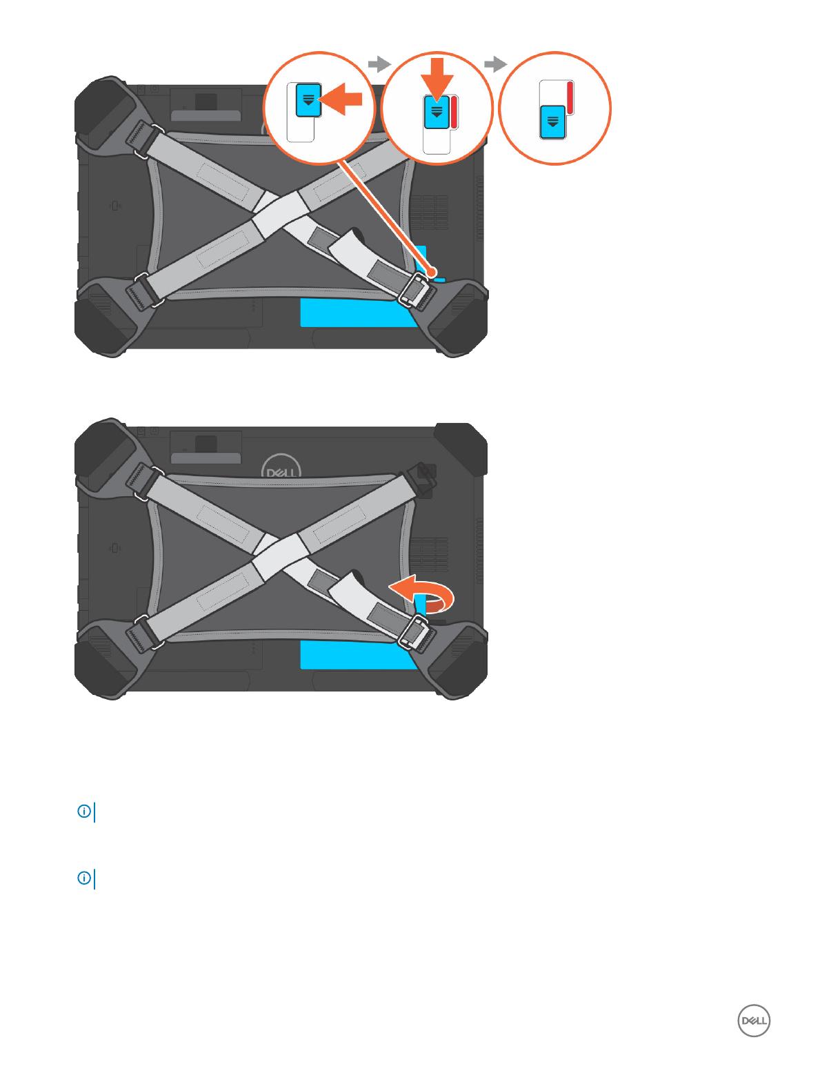
Removing the battery when the cross strap is attached -
Optional
WARNING
: Using an incompatible battery may increase the risk of re or explosion. Replace the battery only with a compatible
battery purchased from Dell. The battery is designed to work with your Dell Tablet. Do not use a battery from any other computer
with your tablet.
WARNING: Before removing or replacing the battery, turn o the computer, disconnect the AC adapter from the electrical outlet
and the tablet, and remove any other external cables from the tablet.
1 Follow the procedure in Before Working Inside Your Computer.
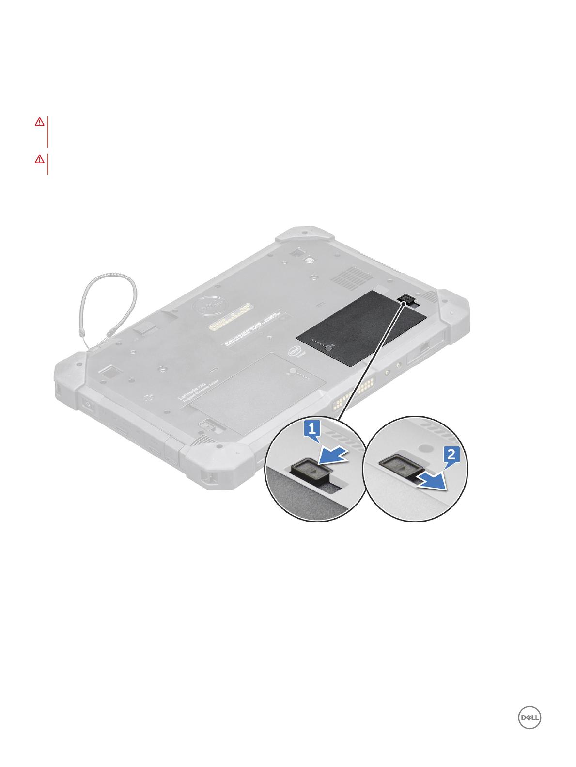
2 Peel o the velcro strap.
12
Removing and installing components
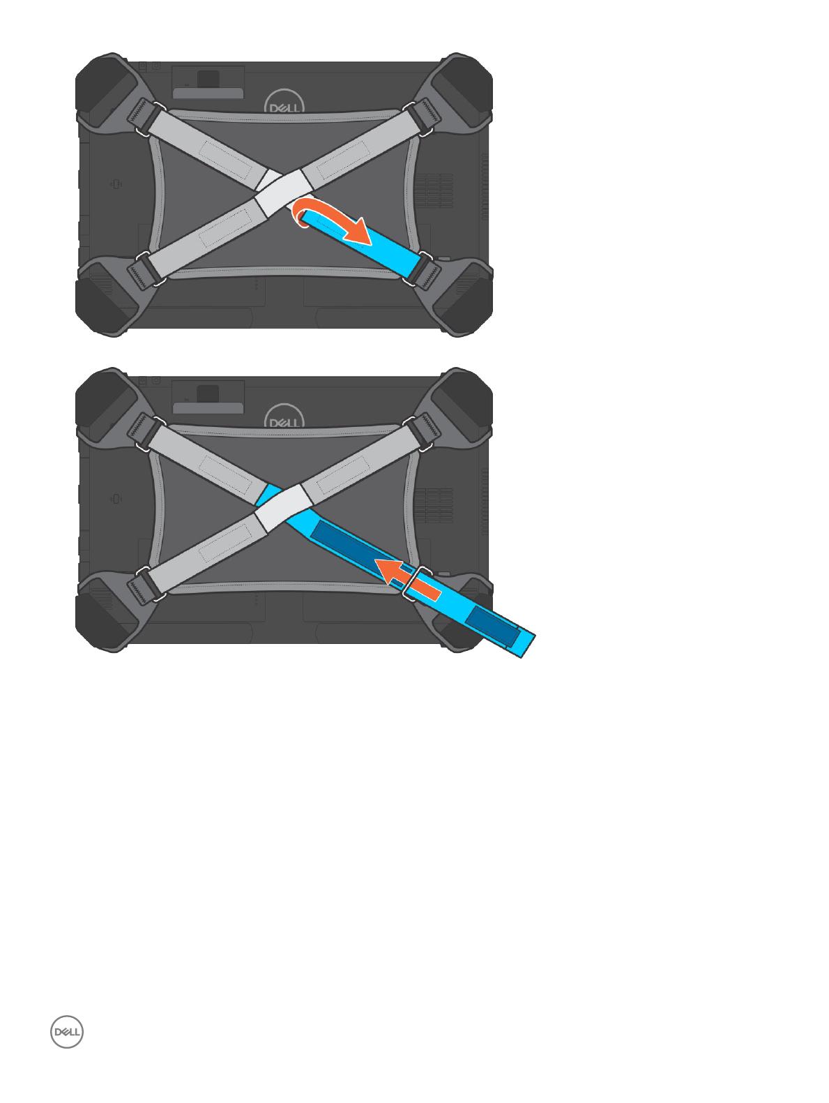
3 Slide the strap and release the strap from the holder to access the battery latch.
4 Slide the battery latch to unlock the battery release latch and then push the latch in a downward direction to release the battery.
Removing and installing components
13
The battery is released from the battery bay.
5 Lift the edge of the battery that pops up to release the battery.
Installing the battery
1 Insert the battery into the battery slot.
NOTE
: Ensure the metal pin of the battery is aligned in place.
2 Slide the battery into the slot until it clicks into place.
3 Make sure the battery latch is back to the locked state.
NOTE
: There are two battery. Perform steps 1 to 3 to install battery 1 and battery 2 on the tablet.
4 Follow the procedure in After working inside your computer.
14
Removing and installing components
Installing the battery when the cross strap is attached
- Optional
1 Insert the battery into the battery slot.
2 Slide the battery into the slot until it clicks into place and locked.
3 Slide the velcro strap into the strap holder.
4 Ax the velcro strap.
5 Follow the procedure in After working inside your computer.
Subscriber Identication Module (SIM) card
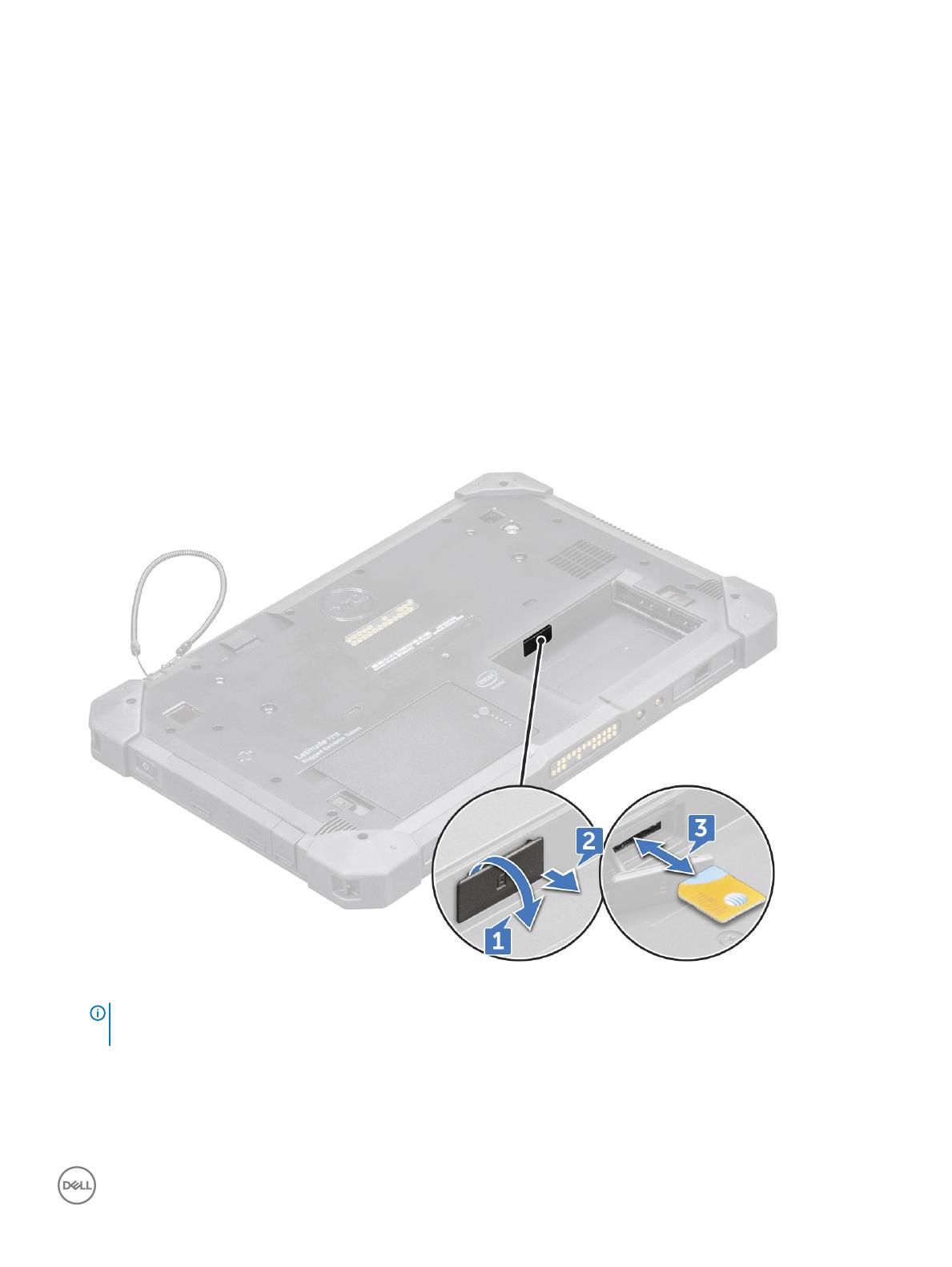
Removing uSIM
1 Follow the procedure in Before working inside your computer.
2 Remove the left battery.
3 Lift the latch [1] and pull the SIM slot cap [2].
4 Pull the SIM from the slot until it is released [3].
NOTE
: Use a at pointed scribe to ease removing the
SIM.
5 Press the SIM slot cap to initial state.
6 Install the:
a Left battery
Removing and installing components
15

Inserting the uSIM
1 Remove the leftbattery
2 To insert the uSIM:
a Lift the latch and remove the SIM slot cap.
b Insert the SIM in the slot until it is locked.
NOTE: Ensure the gold chip is facing down in the slot.
c Press the SIM slot cap to initial state.
3 Follow the procedure in After working inside your computer.
Display assembly
Removing display assembly
1 Follow the procedure in Before working inside your computer.
2 Remove the:
a Battery
3 To remove the display assembly (with plastic scribe):
a Place the display side of system on a smooth at surface.
b Remove the screws (19) that secures the display panel to the tablet.
4 Flip the system so that the display assembly is at top view.
16
Removing and installing components
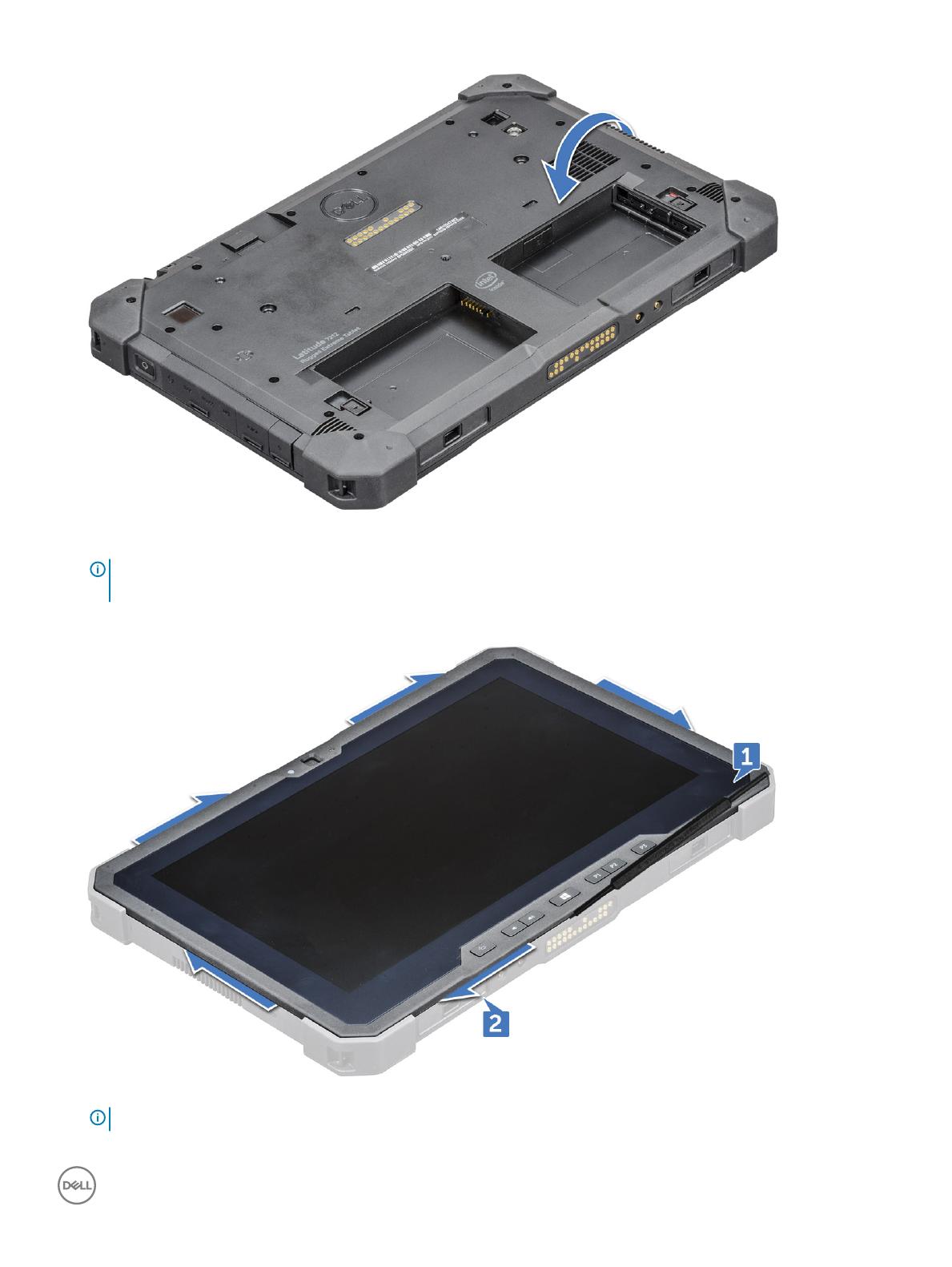
5 Insert a plastic scribe near the Windows button [1].
NOTE
: Pointed tip of the plastic scribe should be inserted to avoid damage to the seal on the LCD and to the clips that
secure the LCD display to the tablet chassis.
6 Pry the edges starting from Windows button clockwise [1,2].
NOTE
: Gently pry the edges evenly to unlock the plastic clips that secures the display assembly to the tablet chassis.
Removing and installing components 17
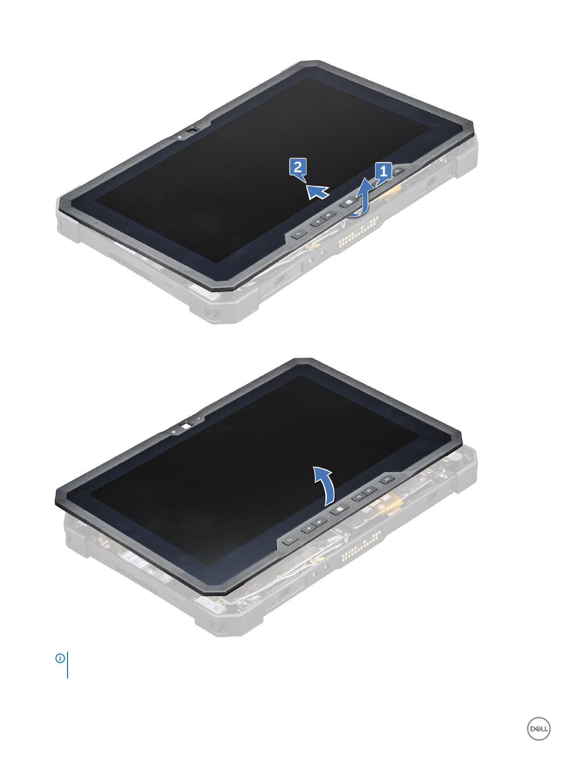
7 Lift the display assembly [1] by angle 15° and slide it from the chassis [2].
8 Flip the display assembly by an angle less than 90°.
NOTE
: Ensure not to ip more than 90° angle, as the display assembly ports and cables are connected to the system board
and may damage the display cables.
9 Before removing display assembly:
a Place the bottom edge of the display panel inside the bottom edge of the rear chassis.
18
Removing and installing components
b Flip open the display panel to 90° angle and lay it angled on the tablet chassis.
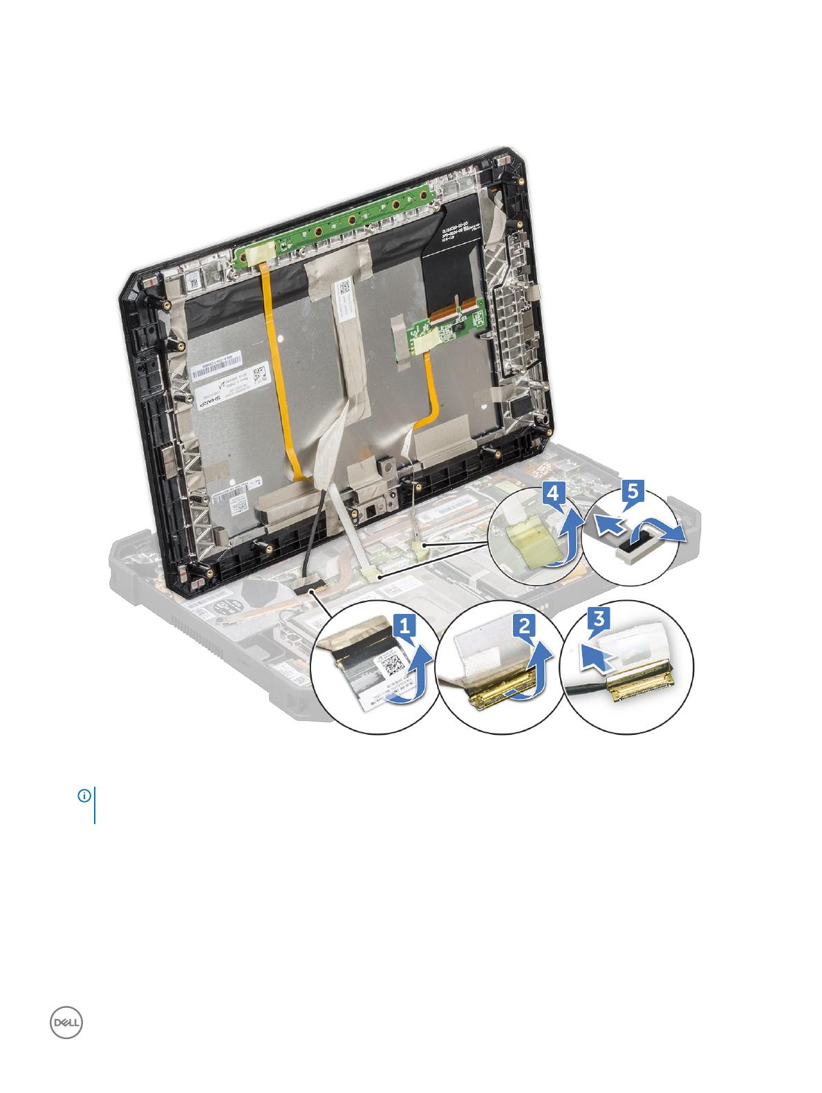
10 To disconnect the display cable:
a Remove the adhesive tape that secures the LVDS cable on the system board [1].
b Lift the latch with a plastic scribe on the system board.
c Disconnect the connector of LVDS cable from the slot by a plastic scribe [2] and remove the cable [3].
d Remove the adhesive tape that secures the Function Key cable on the system board [4].
e Lift the latch by a plastic scribe and release the Touch cable connected to the system board [5].
NOTE
: Disconnect only the display cable from the system board. NEVER disconnect the display cable from the display
panel.
11 Remove the display assembly from the tablet.
Removing and installing components
19
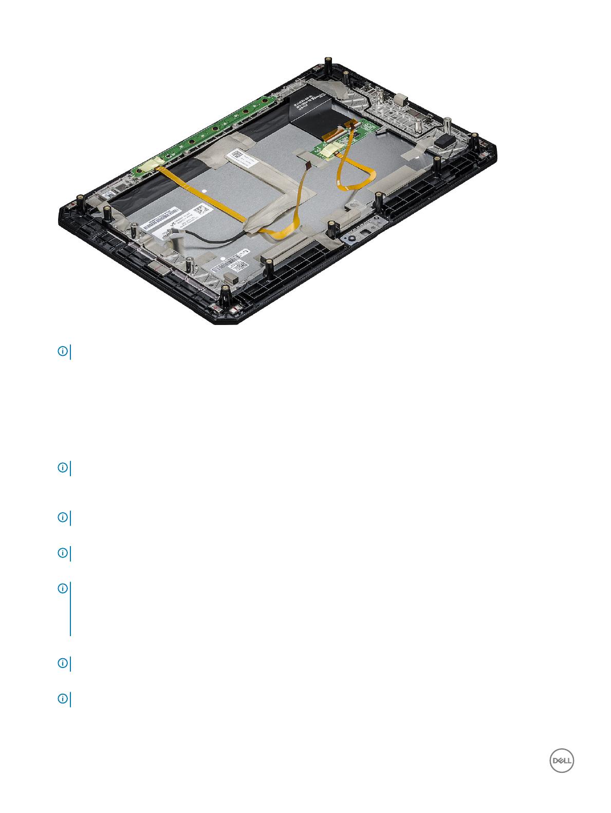
NOTE: DO NOT remove any cable or adhesive tape from the display panel, unless you are replacing the cables separately.
Installing display assembly
1 Place the system chassis on a plane surface.
2 Place the bottom edge of the display assembly inside the bottom edge of the rear chassis.
3 Rest the display assembly by less than 90° angle.
NOTE
: Use a support to attain the required angle.
4 Connect the touch cable, function keys cable, and LVDS cable to the connector on the system board.
5 Release the latch to secure the cables to the respective connecting ports.
NOTE
: Make sure to insert the cable under the clips, if not, the system may not display video after reassembling.
6 Paste the adhesive tapes to secure the connected slots.
NOTE
: Ensure to secure the adhesive tapes, to protect the display assembly from electrostatic discharge damage.
7 Align the display assembly on the tablet chassis and press the edges to snap-in.
NOTE
:
• Ensure that the Window button on the display assembly aligns with the docking pogo pins on the system board chassis.
• Press the edges starting from Windows button clockwise until they snap-in evenly from all sides. Ensure to hear a click
sound when the display assembly is aligned in correct position.
8 Flip the system so that the battery is at top view.
NOTE
: Ensure to place the system in a at surface.
9 Replace the screws (19) to secure the display assembly to the tablet.
NOTE
: DO NOT tighten the screws too much, to avoid damage the screws thread.
10 Install the:
a Battery
20
Removing and installing components
/