Page is loading ...

ZZZGHOOFRP
'HOO/DWLWXGH&3L$
6(59,&(0$18$/


ZZZGHOOFRP
'HOO/DWLWXGH&3L$
6(59,&(0$18$/

____________________
Information in this document is subject to change without notice.
© 1999 Dell Computer Corporation. All rights reserved.
Reproduction in any manner whatsoever without the written permission of Dell Computer Corporation is strictly forbidden.
Trademarks used in this text:
Dell
, the
DELL
logo, and
Latitude
are trademarks
of Dell Computer Corporation;
IBM
is a registered trademark of
International Business Machines Corporation.
Other trademarks and trade names may be used in this document to refer to either the entities claiming the marks and names or their products. Dell
Computer Corporation disclaims any proprietary interest in trademarks and trade names other than its own.
February 1999 P/N 0813P

v
&RQWHQWV
Recommended Tools. . . . . . . . . . . . . . . . . . . . . . . . . . . . . . . . . . . . . . . . . . . . 2
Preparing to Work Inside Your Computer . . . . . . . . . . . . . . . . . . . . . . . . . . . . 2
Screw Identification and Tightening . . . . . . . . . . . . . . . . . . . . . . . . . . . . . . . . 3
ZIF Connectors . . . . . . . . . . . . . . . . . . . . . . . . . . . . . . . . . . . . . . . . . . . . . . . . 4
Field-Replaceable Parts and Assemblies . . . . . . . . . . . . . . . . . . . . . . . . . . . . 5
Removing Field-Replaceable Parts and Assemblies . . . . . . . . . . . . . . . . . . . 12
Hard-Disk Drive Assembly . . . . . . . . . . . . . . . . . . . . . . . . . . . . . . . . . . . . 13
Memory Module Cover . . . . . . . . . . . . . . . . . . . . . . . . . . . . . . . . . . . . . . 14
Memory Modules . . . . . . . . . . . . . . . . . . . . . . . . . . . . . . . . . . . . . . . . . . 15
Keyboard Assembly . . . . . . . . . . . . . . . . . . . . . . . . . . . . . . . . . . . . . . . . . 16
Back Cover Assembly . . . . . . . . . . . . . . . . . . . . . . . . . . . . . . . . . . . . . . . 18
Palmrest Assembly . . . . . . . . . . . . . . . . . . . . . . . . . . . . . . . . . . . . . . . . . 19
Touch-Pad Interface Module . . . . . . . . . . . . . . . . . . . . . . . . . . . . . . . . . . 20
Power Button. . . . . . . . . . . . . . . . . . . . . . . . . . . . . . . . . . . . . . . . . . . . . . 21
Display Assembly . . . . . . . . . . . . . . . . . . . . . . . . . . . . . . . . . . . . . . . . . . 21
Display Assembly Bezel. . . . . . . . . . . . . . . . . . . . . . . . . . . . . . . . . . . . . . 23
Display Assembly Latch. . . . . . . . . . . . . . . . . . . . . . . . . . . . . . . . . . . . . . 23
LCD Panel . . . . . . . . . . . . . . . . . . . . . . . . . . . . . . . . . . . . . . . . . . . . . . . 24
12.1-Inch LCD Displays . . . . . . . . . . . . . . . . . . . . . . . . . . . . . . . . . . . 24
13.3-Inch LCD Displays . . . . . . . . . . . . . . . . . . . . . . . . . . . . . . . . . . . 26
LCD Display Hinge. . . . . . . . . . . . . . . . . . . . . . . . . . . . . . . . . . . . . . . . . . 28
Display-Assembly Top Cover . . . . . . . . . . . . . . . . . . . . . . . . . . . . . . . . . 28
Bottom Case Assembly . . . . . . . . . . . . . . . . . . . . . . . . . . . . . . . . . . . . . . 28
Modular Bay Devices (Diskette Drive, CD-ROM Drive, Battery,
or Travel Module). . . . . . . . . . . . . . . . . . . . . . . . . . . . . . . . . . . . . . . . . . . 30
Audio Shield . . . . . . . . . . . . . . . . . . . . . . . . . . . . . . . . . . . . . . . . . . . . . . 30
Audio Board . . . . . . . . . . . . . . . . . . . . . . . . . . . . . . . . . . . . . . . . . . . . . . 31

vi
Bottom Case Bracket. . . . . . . . . . . . . . . . . . . . . . . . . . . . . . . . . . . . . . . . 32
Module Latch Assemblies . . . . . . . . . . . . . . . . . . . . . . . . . . . . . . . . . . . . 33
Speakers . . . . . . . . . . . . . . . . . . . . . . . . . . . . . . . . . . . . . . . . . . . . . . . . . 34
System Board Assembly . . . . . . . . . . . . . . . . . . . . . . . . . . . . . . . . . . . . . 35
Exhaust Fan . . . . . . . . . . . . . . . . . . . . . . . . . . . . . . . . . . . . . . . . . . . . . . 38
I/R Board . . . . . . . . . . . . . . . . . . . . . . . . . . . . . . . . . . . . . . . . . . . . . . . . . 39
Reserve Battery . . . . . . . . . . . . . . . . . . . . . . . . . . . . . . . . . . . . . . . . . . . 40
,QGH[
)LJXUHV
Figure 1. Computer Orientation . . . . . . . . . . . . . . . . . . . . . . . . . . . . . . . . 1
Figure 2. Main Battery Assembly Removal . . . . . . . . . . . . . . . . . . . . . . . 3
Figure 3. Screw Identification . . . . . . . . . . . . . . . . . . . . . . . . . . . . . . . . . 3
Figure 4. Disconnecting an Interface Cable . . . . . . . . . . . . . . . . . . . . . . . 4
Figure 5. Exploded View—Computer. . . . . . . . . . . . . . . . . . . . . . . . . . . 12
Figure 6. Hard-Disk Drive Assembly Removal . . . . . . . . . . . . . . . . . . . . 13
Figure 7. Memory Module Cover Removal . . . . . . . . . . . . . . . . . . . . . . 14
Figure 8. Memory Module Removal . . . . . . . . . . . . . . . . . . . . . . . . . . . 15
Figure 9. Removing the Keyboard Assembly Screws . . . . . . . . . . . . . . 16
Figure 10. Keyboard Assembly Removal . . . . . . . . . . . . . . . . . . . . . . . . . 17
Figure 11. Back Cover Assembly Removal . . . . . . . . . . . . . . . . . . . . . . . 18
Figure 12. Palmrest Assembly Removal . . . . . . . . . . . . . . . . . . . . . . . . . 19
Figure 13. Touch-Pad Interface Module Removal . . . . . . . . . . . . . . . . . . 21
Figure 14. Display Assembly Removal. . . . . . . . . . . . . . . . . . . . . . . . . . . 23
Figure 15. Display Assembly Bezel Removal (12.1-Inch Display Shown) 25
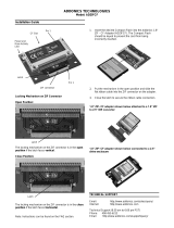
Figure 16. LCD Panel Removal (12.1-Inch Display) . . . . . . . . . . . . . . . . . 27
Figure 17. Cable Layout for the 12.1-Inch LCD Panel . . . . . . . . . . . . . . . 28
Figure 18. LCD Panel Removal (13.3-Inch Display) . . . . . . . . . . . . . . . . . 29
Figure 19. Two-Piece Cable Layout for the 13.3-Inch LCD Panel . . . . . . 30
Figure 20. Bottom Case Assembly . . . . . . . . . . . . . . . . . . . . . . . . . . . . . 34
Figure 21. Modular Bay Device Removal . . . . . . . . . . . . . . . . . . . . . . . . . 35
Figure 22. Audio Board Removal . . . . . . . . . . . . . . . . . . . . . . . . . . . . . . . 37
Figure 23. Bottom Case Bracket Removal . . . . . . . . . . . . . . . . . . . . . . . 38
Figure 24. Module Latch Assemblies Removal . . . . . . . . . . . . . . . . . . . . 40
Figure 25. Left Slider . . . . . . . . . . . . . . . . . . . . . . . . . . . . . . . . . . . . . . . . 41
Figure 26. System Board Assembly Removal . . . . . . . . . . . . . . . . . . . . . 42

vii
Figure 27. Processor Module . . . . . . . . . . . . . . . . . . . . . . . . . . . . . . . . . . 44
Figure 28. Exhaust Fan Removal . . . . . . . . . . . . . . . . . . . . . . . . . . . . . . . 45
Figure 29. I/R Board Removal. . . . . . . . . . . . . . . . . . . . . . . . . . . . . . . . . . 46
Figure 30. Reserve Battery Installation . . . . . . . . . . . . . . . . . . . . . . . . . . 47
7DEOHV
Table 1. Parts and Assemblies . . . . . . . . . . . . . . . . . . . . . . . . . . . . . . . . 5

viii
5HDG7KLV)LUVW
A prerequisite for using this manual to service Dell computer systems is a basic
knowledge of IBM-compatible PCs and prior training in IBM-compatible PC trou-
bleshooting techniques. In addition to information provided in this manual, Dell
provides the
System Users Guide
for troubleshooting procedures and instruc-
tions on using the Dell Diagnostics to test the computer system.
1RWHV&DXWLRQVDQG:DUQLQJV
Throughout this guide, blocks of text may be accompanied by an icon and printed
in bold type or in italic type. These blocks are notes, cautions, and warnings, and
they are used as follows:
NOTE: A NOTE indicates important information that helps you make better use
of your computer system.
&$87,21$&$87,21LQGLFDWHVHLWKHUSRWHQWLDOGD PD JHWRK DUG
ZDUHRUORVVRIGDWDDQGWHOOV\RXKRZWRDYRLGWKHSUREOHP
:$51,1*$:$51,1*LQGLFDWHV WKHSRWHQW LDOIRUERGLO\KDUP DQG
WHOOV\RXKRZWRDYRLGWKHSUREOHP

Dell Latitude CPiA Service Manual 1
'HOO/DWLWXGH&3L$
6HUYLFH0DQXDO
This manual provides instructions for removing and replacing
field-replaceable components, assemblies, and subassemblies in
your Dell Latitude portable computer. Unless otherwise noted,
each procedure in this chapter assumes the following:
The computer and any attached peripherals are turned off, and the
peripherals are disconnected from the input/output (I/O) panel on
the back of the computer.
A part can be replaced by performing the removal procedure in reverse
order.
When the display assembly is open nearly 180 degrees, use a book or
something similar to support it. The angle of the display assembly with
respect to the bottom case should never be allowed to exceed 180 degrees.
Also, when performing the procedures in this manual, the locations or
directions relative to the computer are as shown in Figure 1 unless
otherwise specified.
)LJXUH&RPSXW HU2ULHQWDWLRQ
right side
left side
back of computer
front of computer

2 Dell Latitude CPiA Service Manual
5HFRPPHQGHG7RROV
Most of the procedures in this manual require the use of one or more of the
following tools:
Number 0 and number 1 magnetized Phillips-head screwdrivers
Small flat-blade screwdriver
Small plastic scribe
Processor extractor
3UHSDULQJWR:RUN,QVLGH<RXU&RPSXWHU
Before you start to work on the computer, perform the following steps:
1. Save any work in progress and close all open applications.
2. Turn off the computer and any attached peripherals.
NOTE: Make sure the computer is turned off and not in suspend-to-
disk mode. If you cannot shut down the computer using the computer’s
operating system, press the power button for 4 seconds.
3. If the computer is docked in a C/Dock Expansion Station or C/Port
Advanced Port Replicator (APR), undock the computer.
4. Disconnect the computer and any attached peripherals from AC power
sources to reduce the potential for personal injury or shock. Also
disconnect any telephone or telecommunications lines from the computer.
5. Remove the power cord.
6. Disconnect all other external cables from the computer.
7. Remove any installed PC Cards.
&$87,210DNHVXUHWKHZRUNVXUIDFHLVFOHDQWRSUHYHQWVFUDWFKLQJ
WKHFRPSXWHUFRYHU
8. Remove the main battery assembly from the battery bay.
Slide the battery bay latch away from the center of the computer. Then
slide the battery out of the battery bay (see Figure 2).

Dell Latitude CPiA Service Manual 3
&$87,217RDYRLGGDPDJLQJWKHV\VWHPERDUGWKHEDWWHU\PXVW
EHUHPRYHGEHIRUH\RXVHUYLFHWKHF RPS XWHU
)LJXUH0DLQ%DWWHU\$VVHPEO\5HPRYDO
9. Ground yourself by touching the unpainted metal surface of the I/O panel
on the back of the computer.
While you work, periodically touch the I/O panel to dissipate any static
electricity that might harm components.
6FUHZ,GHQWLILFDWLRQD Q G7LJ KWHQLQJ
The illustrations in the following removal procedures provide the correct screw
length as part of the screw’s label. A graphic for that length screw is also
included in the illustration. Examples are shown in Figure 3. Match the actual
screw to the graphic in the illustration to check for correct length.
)LJXUH6FUHZ,GHQWLILFDWLRQ
&$87,21:KHQUHLQVWD OOLQJDVFUHZ\RXPXVWXVHDVFUHZ RIWKH
FRUUHFWOHQJWK2WKHUZLVHKDUGZDUHGDP DJ HFRXOGUHVXOW0DNHVXUH
WKDWWKHVFUHZLVSURSHUO\DOLJQHGZLWKLWVFRUUHVSRQGLQJKROHDQG
DYRLGRYHUWLJKWHQLQJ
EDWWHU\ED\ODWFK
EDWWHU\

4 Dell Latitude CPiA Service Manual
=,)&RQQHFWRUV
Some of the computer’s interface connectors are zero insertion force (ZIF)
connectors. These connectors are not removable, but they must be released
to disconnect a cable from them (see Figure 4).
)LJXUH'LVFRQQHFWLQJDQ,QWHUIDFH&DEOH
&$87,217KH=,)FRQQHFWRUVDUHIUDJLOH7R DYRLGGDP DJHGRQRW
DSSO\WRRPXFKSUHVVXUHWRWKHPRYDEOHSDUWRIWKHFRQQHFWRU
To disconnect an interface cable from a ZIF connector, perform the following
steps:
1. Insert a small flat-blade screwdriver under the movable part of the
connector.
2. Pull gently upward on the movable part of the connector until it releases
the interface cable.
3. Grasp the interface cable and pull it out of the connector.
To reconnect an interface cable to a ZIF connector, perform the following
steps:
1. Use a small flat-blade screwdriver to open the movable part of the ZIF
connector.
2. Orient the end of the interface cable with the ZIF connector, and insert the
end of the cable into the connector.
3. While holding the cable in place, close the ZIF connector.
To ensure a firm connection, make sure the ZIF connector is completely
closed.
movable part of
connector
(do not remove)

Dell Latitude CPiA Service Manual 5
)LHOG5H SODFHDEOH3DUWVDQG$VVHPEOLHV
Table 1 lists the parts and assemblies available for the computer. Some parts
may only be available as part of a service kit or assembly and are provided for
reference only. The subsections that follow Table 1 provide instructions for
removing and replacing these parts and assemblies.
7DEOH3 DUWVDQ G$VVHP EOL HV
3DUWRU$VVHPEO\1DPH 2UGHU1DPH )LJXUH
$&$GDSWHUDQG3RZHU&RUGV
Customer kit, AC adapter CUS,ADPT,AC,EXT,20V,70W,
NBK,CPiA
AC adapter ADPT,AC,EXT,20V,70W,3WIRE,
CPiA
Power cable, U.S. CORD,PWR,110V,6F,AC,3W\3P,US
$XGLR%RDUG
Service kit, audio board SVC,PWA,AUDIO,CPiA 22
$XGLR6KLHOG
Audio shield SHLD,W/SPR,AUDIO CRD 22
%DFN&RYHU$VVHPEO\
Service kit, back cover
assembly
SVC,SUBASSY,
BK CVR/DOOR,I/O,CPiA
11
Back cover assembly ASSY,BK PLT/DOOR,I/O,CPiA
Docking bar BAR,DOOR,DCKG,MET
Docking door DOOR,DCKG,PLSTC,I/O
%DWWHU\0DLQ
Customer kit, main battery CUS,BTRY,MN,14.4V,8CELL,
LITH
2
Main battery BTRY,MN,14.4V,8CELL,LITH
%DWWHU\5HVHUYH
Service kit, reserve battery SVC,BTRY,RSRV,7.2V,30MAH,6,
NIHD
29
Reserve battery BTRY,RSRV,7.2V,30MAH,6,
NIHD
Reserve battery sponge
pad
PAD,FOAM,BRTY,RSRV,CPiA
%RWWRP&DVH $VVHPEO\
Bottom case assembly ASSY,CVR,BTM,PLSTC,
BASE,CPiA
5, 26

6 Dell Latitude CPiA Service Manual
%RWWRP&DVH%UDFNHW
Bottom case bracket
assembly
ASSY,BRKT,CASE,BTM 20, 23
&' 520'ULYH6XEDVV HPEO\
Service kit, CD-ROM drive SVC,SUBASSY,CD,24X,NBK 21
CD-ROM drive bezel BZL,CD
24X CD-ROM drive CD,680M,INT,NBK
CD-ROM drive interface
board
PWA,CD/FDD INTERCONN,SE
Bottom CD-ROM drive
cover
CVR,BTM,PLSTC,CD,CPiA
Top CD-ROM drive cover CVR,TOP,PLSTC,CD,CPiA
CD-ROM drive shield SHLD,CD,CPiA
CD-ROM drive label LBL,REG,CD,24X
'LVNHWWH'ULYH6XE D VVHPEO\
Diskette drive service kit SVC,SUBASSY,FD,F3,
INT/EXT,CPiA
21
Diskette drive subassembly SUBASSY,FD,F3,INT/EXT,CPiA
Diskette drive FD,F3,CPiA
Diskette drive assembly
bottom cover
CVR,BTM,PLSTC,FD,F3,CPiA
Diskette drive assembly
top cover
CVR,TOP,PLSTC,FD,F3,CPiA
Diskette drive assembly
interface board
PWA,INTFC,FD,F3,CPiA
Diskette drive assembly
interface cable
CBL,FPC,FD,F3,CPiA
Diskette drive assembly
shield
SHLD,FD,F3,CPiA
([KDXVW)DQ
Service kit, exhaust fan SVC,FAN,25X25X10,CPiA 27
7DEOH3DUWVDQG$VVHPEOLHVFRQWLQX HG
3DUWRU$VVHPEO\1DPH 2UGHU1DPH )LJXUH

Dell Latitude CPiA Service Manual 7
+DUG'LVN'ULYH$VVHPEOLHV
Hard-disk drive,
subassembly
SUBASSY,HD,
xxxxx
,I,
yyy
MM,
CPiA
*
6
Hard-disk drive
HD,
xxxxx
,I,
yy
MM,NBK,
zzz
*
Hard-disk drive interface
board
PWA,INTERCONN,HD,CPiA
Hard-disk drive bracket BRKT,HD,CPiA
+DUG'LVN'ULYH%UDFNHW'RRU$VVHPEO\
Hard-disk drive carrier bracket/
door assembly service kit
SVC,ASSY,BRKT/DOOR,
HD,CPiA
6
Hard-disk drive carrier
door
DOOR,HD,12.5MM,CPiA
Hard-disk drive carrier
bracket
BRKT,HD,12.5MM,CPiA
Hard-disk drive carrier
insulator
INSUL,HD,CPiA
Hard-disk drive carrier
screws
SCR,M3X3,PHH,LP,ZPS
,5%RDUG
Service kit, I/R board SVC,PWA,FAST IR,CPiA 28
.H\ERDUGV
Keyboard, Belgian KYBD,88,BEL,CPiA 10
Keyboard, Chinese KYBD,87,CHI,CPiA
Keyboard, Danish KYBD,88,DEN,CPiA
Keyboard, French KYBD,88,FR,CPiA
Keyboard, French/Canadian KYBD,87,FR CAN,CPiA
Keyboard, German KYBD,88,GER,CPiA
Keyboard, Italian KYBD,88,ITALIAN,CPiA
Keyboard, Japanese KYBD,90,JPN,CPiA
Keyboard, Korean KYBD,87,KOR,CPiA
Keyboard, Latin American KYBD,88,LAC,CPiA
Keyboard, Norwegian KYBD,88,NOR,CPiA
Keyboard, Portuguese KYBD,88,PORTUGEUSE,CPiA
* Substitute the drive capacity for xxxxx
,
the drive height for yy
,
and the
manufacturer for zzz.
7DEOH3DUWVDQG$VVHPEOLHVFRQWLQX HG
3DUWRU$VVHPEO\1DPH 2UGHU1DPH )LJXUH

8 Dell Latitude CPiA Service Manual
.H\ER D UGVFRQWLQXHG
Keyboard, Russian KYBD,87,RUS,CPiA
Keyboard, Spanish KYBD,88,SPN,CPiA
Keyboard, Swedish/Finnish KYBD,88,SWE,CPiA
Keyboard, Swiss KYBD,88,SWI,CPiA
Keyboard, Thai KYBD,87,THAI,CPiA
Keyboard, English (U.K.) KYBD,88,UK,CPiA
Keyboard, English (U.S.) KYBD,87,DOM,CPiA
'LVSOD\%DFN&RYHU
Display top-cover service kit,
13.3/12.1-inch display
SVC,ASSY,CVR,TOP,LCD,CPiA
Display top cover CVR,TOP,LCD,TFT,CPiA
Display top-cover EMI shield SHLD,EMI,DIS,TFT,CPiA
/&'$VVHPEOLHV,QFK'LVSOD\
12.1-inch LCD/Cable service
kit, including LCD, brackets,
cable, and inverter
SVC,LCD/CBL/INV,TFT,zzz,12.1”,
CPiA
*
18
Bezel service kit, 12.1-inch
display
SVC,BZL,LCD,12.1”,CPiA 14, 17
Display assembly bezel BZL,LCD,TFT,12.1”,CPiA
Bezel retaining screw
covers, upper corners,
12.1-inch display
CVR,SCR,TOP,RND,ADH
Bezel retaining screw
covers, lower
CVR,SCR,BTM,OVAL,ADH
Display-assembly-bezel
retaining screw covers,
latch, 12.1-inch display
CVR,SCR,TOP,OVAL,SM,ADH,12.1
/&'$VVHPEOLHV,QFK;*$'LVSOD\
13.3-inch LCD/Cable service
kit, including LCD, brackets,
cable, inverter, and bezel
SVC,LCD/CBL/INV,TFT,zzz,13.3”,
CPiA
*
15, 17
/&'/D WFK$VV HPEO\
Latch service kit SVC,LATCH,DIS,BZL,CPiA 14, 15
* Substitute the drive capacity for xxxxx
,
the drive height for yy
,
and the
manufacturer for zzz.
7DEOH3DUWVDQG$VVHPEOLHV
FRQWLQXHG
3DUWRU$VVHPEO\1DPH 2UGHU1DPH )LJXUH

Dell Latitude CPiA Service Manual 9
/&'3DUWV0LVFHOODQHRXV
13.3/12.1-inch display
Right hinge HNG,RT,LCD,TFT 14, 15
Left hinge HNG,LF,LCD,TFT 14, 15
0HPRU\
Customer kit, memory
module, 32-MB
32MB,DIMM,SDRAM,LAT
CPIA,FACT
Customer kit, memory
module, 64-MB
64MB,DIMM,SDRAM,LAT
CPIA,FACT
Customer kit, memory
module, 128-MB
128MB,DIMM,SDRAM,LAT
CPIA,FACT
0HPRU\'RRU
Service kit, memory door
assembly
SVC,SUBASSY,DOOR,
MEM/BIOS,CPiA
7
Memory/BIOS door
subassembly
SUBASSY,DOOR,
MEM/BIOS,NB,CPiA
0LVFHOODQHRXV3DUWV
Touch-pad bracket BRCKT,TPAD,CPiA 13
Air flow duct GDE,INTK,AIR,FAN,PLSTC,CPiA 26
3DOPUHVW$VVHPEO\
Service kit, palmrest
assembly
SVC,SUBASSY,PLMRST,CPiA 12
Palmrest assembly ASSY,PLMRST,GRY,CPiA
Power button SWT,PWR SW, CPiA
Power button spring SPR,PWR SW,CPiA
7DEOH3DUWVDQG$VVHPEOLHVFRQWLQX HG
3DUWRU$VVHPEO\1DPH 2UGHU1DPH )LJXUH

10 Dell Latitude CPiA Service Manual
6FUHZV
LCD panel SCR,M2X4.5,PHH,LP,ZPS 18, 19
LCD hinge SCR,M3X5,PHH,LP,ZPS 16
LCD bezel SCR,M2X4.5,PHH,LP,ZPS 17
Keyboard SCR,M2.6X12,PHH,LP,ZPS 9
Thermal cooling assembly SCR,M2X3.5,PHH,LP,ZPS 26
Touch pad SCR,M2.6X1.8,PHH,XLP,ZPS 13
Palmrest, front edge SCR,M2.6X12,PHH,LP,ZPS 12
Palmrest, hard-disk drive
area
SCR,M2.6X5,PHH,LP,ZPS 12
I/R board SCR,M2.6X5,PHH,LP,ZPS 28
Back cover SCR,M2.6X5,PHH,LP,ZPS 11
Audio board SCR,M2.6X5,PHH,LP,ZPS 22
Bottom-case bracket SCR,M2.6X5,PHH,LP,ZPS 23
Exhaust fan SCR,M2.6X12,PHH,LP,ZPS 27
6SHDNHUV
Left speaker assembly SUBASSY,SPKR,LF,W/WIRES
Right speaker assembly SUBASSY,SPKR,RT,W/WIRES
6\VWHP%RDUG$VVHPEO\
System board assembly,
CPiA, service kit
SVC,ASSY,PRM/
PWA,ENGINE,CPiA
26
System board assembly,
CPiA, service kit
SVC,ASSY,PRM/
PWA,ENGINE,CPiA
Service tag installation
diskette
DSK,BIOS,FLDSVC,F3,US,CP
BIOS flash diskette KIT,BIOS,FLASH,UPG,F3,CP
Diagnostic diskette KIT,DSK,DIAG,F3,CPiA,WW
System board assembly ASSY,PRM/PWA,ENGINE,
CPiA
7DEOH3DUWVDQG$VVHPEOLHVFRQWLQXHG
3D UWR U$VVH PEO\1D PH 2UGHU 1DPH )LJXU H

Dell Latitude CPiA Service Manual 11
6\VWHP%RDUG$VVHPEO\FRQWLQXHG
System board assembly
(366 MHz processor
with 13.3-in display;
300 MHz processor with
12.1-in display)
ASSY,PRM/PWA,ENGINE,
CPiA
System-board engine
subassembly
SUBASSY,PWA/ENGINE,CPiA
I/R board PWA,FAST IR,CPiA
Microphone boot GRMT,RBR,BOOT,MCPHN
Main system board PWA,PLN,0M,NB,CPiA
Video/PC Card
board
PWA,DTRBD,VID/PCMCIA,CPiA
LED board PWA,LED,CPiA
Exhaust fan and
cable
FAN,25X25X10,CPiA
Microphone MCPHN,CPiA
Reserve battery BTRY,RSRV,7.2,30MAH,6,NIHD
Foam pad PAD,FOAM,BTRY,RSRV,CPiA
7KHUPDO&RROLQJ$VVHPEO\
Service kit, thermal cooling
subassembly
SVC,SUBASSY,HTSNK,
CPU,HYB,CPiA
26
7RXFK3DG
Touch-pad service kit SVC,TPAD,SQ,INTFC,CPiA 13
Touch-pad subassembly TPA,INTFC,CPiA
7DEOH3DUWVDQG$VVHPEOLHV
FRQWLQXHG
3DUWRU$VVHPEO\1DPH 2UGHU1DPH )LJXUH

12 Dell Latitude CPiA Service Manual
5HPRYLQJ)LH OG5HSODFHDEOH3DUWV
DQG $VVHPEOLHV
)LJXUH([SORGHG9LHZ³&RPSXWHU
The following subsections provide instructions for removing and replacing
field-replaceable parts and assemblies.
display
assembly
keyboard
palmrest
assembly
main battery
modular bay
device
back cover assembly
bottom case assembly
/