
vacon 100
ac drives
integrated bacnet
installation manual
®


vacon • 1
24-hour support +358 (0)201 212 575 • Email: vac[email protected]
Table of Contents
Document: DPD00091C
Version release date: 17.2.15
1. Safety................................................................................................................2
1.1 Danger.................................................................................................................................2
1.2 Warnings .............................................................................................................................3
1.3 Earthing and earth fault protection....................................................................................4
2. BACnet - general info .......................................................................................5
3. BACnet technical data.......................................................................................6
3.1 BACnet MS/TP protocol ......................................................................................................6
3.2 BACnet IP protocol..............................................................................................................6
4. Programming....................................................................................................7
4.1 BACnet MS/TP parameters and monitoring values ...........................................................7
4.2 BACnet IP parameters and monitoring values...................................................................8
4.2.1 Ethernet common settings.....................................................................................8
4.2.2 BACnet IP settings..................................................................................................9
4.3 BACnet MS/TP parameter descriptions ...........................................................................11
4.3.1 BACnet MS/TP Parameters..................................................................................11
4.3.2 BACnet MS/TP monitoring values........................................................................12
4.4 BACnet IP parameter descriptions...................................................................................13
4.4.1 Ethernet common settings...................................................................................13
4.4.2 BACnet IP settings................................................................................................14
4.4.3 BACnet IP monitoring values ...............................................................................15
5. Installation......................................................................................................16
5.1 Vacon® 100 .......................................................................................................................16
5.1.1 Prepare for use through Ethernet........................................................................17
5.1.2 Prepare for use through RS485 ...........................................................................20
5.2 Installation in Vacon® 100 X.............................................................................................24
5.2.1 Prepare for use through Ethernet........................................................................24
5.2.2 Prepare for use through RS485 ...........................................................................25
6. Communications .............................................................................................27
6.1 Object types and properties supported ............................................................................27
6.1.1 Binary Value Object ..............................................................................................28
6.1.2 Analogue Value Object..........................................................................................29
6.2 Control word bits...............................................................................................................31
6.3 Status word bits ................................................................................................................31
7. Fault tracing ...................................................................................................32
7.1 Typical fault conditions .....................................................................................................32
7.2 Other fault conditions .......................................................................................................33
8. Quick setup .....................................................................................................35
9. Annex - Protocol implementation conformance statement ............................36

1
vacon • 2 Safety
Tel. +358 (0) 201 2121 • Fax +358 (0)201 212 205
1. SAFETY
This manual contains clearly marked cautions and warnings that are intended for your personal
safety and to avoid any unintentional damage to the product or connected appliances.
Please read the information included in cautions and warnings carefully.
The cautions and warnings are marked as follows:
1.1 Danger
Table 1. Warning signs
= DANGER! Dangerous voltage
= WARNING or CAUTION
= Caution! Hot surface
The components of the power unit are live when the drive is connected to mains
potential. Coming into contact with this voltage is extremely dangerous and may
cause death or severe injury.
The motor terminals U, V, W and the brake resistor terminals are live when the
AC drive is connected to mains, even if the motor is not running.
After disconnecting the AC drive from the mains, wait until the indicators on the
keypad go out (if no keypad is attached, see the indicators on the cover). Wait 5
more minutes before doing any work on the connections of the drive. Do not open
the cover before this time has expired. After expiration of this time, use a mea-
suring equipment to absolutely ensure that no
voltage is present.
Always ensure
absence of voltage before starting any electrical work!
The control I/O-terminals are isolated from the mains potential. However, the
relay outputs and other I/O-terminals may have a dangerous control voltage
present even when the AC drive is disconnected from mains.
Before connecting the AC drive to mains make sure that the front and cable cov-
ers of the drive are closed.
During a ramp stop (see the Application Manual), the motor is still generating
voltage to the drive. Therefore, do not touch the components of the AC drive
before the motor has completely stopped. Wait until the indicators on the keypad
go out (if no keypad is attached, see the indicators on the cover). Wait additional 5
minutes before starting any work on the drive.
9000.emf
13006.emf
9001.emf
9000.emf
9000.emf
9000.emf
9000.emf
9000.emf
9000.emf

Safety vacon • 3
24-hour support +358 (0)201 212 575 • Email: vac[email protected]
1
1.2 Warnings
The AC drive is meant for fixed installations only.
Do not perform any measurements when the AC drive is connected to the mains.
The earth leakage current of the AC drives exceeds 3.5mA AC. According to stan-
dard EN61800-5-1, a reinforced protective ground connection must be ensured.
See Chapter 1.3.
If the AC drive is used as a part of a machine, the machine manufacturer is
responsible for providing the machine with a supply disconnecting device (EN
60204-1).
Only spare parts delivered by Vacon can be used.
At power-up, power brake or fault reset the motor will start immediately if the
start signal is active, unless the pulse control for
Start/Stop logic
has been
selected
.
Furthermore, the I/O functionalities (including start inputs) may change if param-
eters, applications or software are changed. Disconnect, therefore, the motor if
an unexpected start can cause danger.
The motor starts automatically after automatic fault reset if the auto restart
function is activated. See the Application Manual for more detailed information.
Prior to measurements on the motor or the motor cable, disconnect the motor
cable from the AC drive.
Do not touch the components on the circuit boards. Static voltage discharge may
damage the components.
Check that the EMC level of the AC drive corresponds to the requirements of your
supply network.
Wear protective gloves when you do mounting, cabling or maintenance opera-
tions. There can be sharp edges in the AC drive that can cause cuts.
13006.emf
13006.emf
13006.emf
13006.emf
13006.emf
13006.emf
13006.emf
13006.emf
13006.emf
13006.emf
13006.emf

1
vacon • 4 Safety
Tel. +358 (0) 201 2121 • Fax +358 (0)201 212 205
1.3 Earthing and earth fault protection
The AC drive must always be earthed with an earthing conductor connected to the earthing terminal
marked with .
The earth leakage current of the drive exceeds 3.5mA AC. According to EN61800-5-1, one or more
of the following conditions for the associated protective circuit must be satisfied:
a) The protective conductor must have a cross-sectional area of at least 10 mm2 Cu or 16
mm2 Al, through its total run.
b) Where the protective conductor has a cross-sectional area of less than 10 mm2 Cu or 16
mm2 Al, a second protective conductor of at least the same cross-sectional area must be
provided up to a point where the protective conductor has a cross-sectional area not less
than 10 mm2 Cu or 16 mm2 Al.
c) Automatic disconnection of the supply in case of loss of continuity of the protective conduc-
tor.
The cross-sectional area of every protective earthing conductor which does not form part of the
supply cable or cable enclosure must, in any case, be not less than:
-2.5mm
2
if mechanical protection is provided or
-4mm
2
if mechanical protection is not provided.
The earth fault protection inside the AC drive protects only the drive itself against earth faults in the
motor or the motor cable. It is not intended for personal safety.
Due to the high capacitive currents present in the AC drive, fault current protective switches may
not function properly.
CAUTION!
Do not perform any voltage withstand tests on any part of the AC drive. There is
a certain procedure according to which the tests must be performed. Ignoring
this procedure may result in damaged product.
NOTE! You can download the English and French product manuals with applicable safety,
warning and caution information from www.vacon.com/downloads
.
REMARQUE Vous pouvez télécharger les versions anglaise et française des manuels produit
contenant l’ensemble des informations de sécurité, avertissements et mises en garde
applicables sur le site www.vacon.com/downloads
.
13006.emf
13006.emf

BACnet - general info vacon • 5
24-hour support +358 (0)201 212 575 • Email: vac[email protected]
2
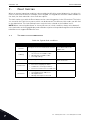
2. BACNET - GENERAL INFO
BACnet stands for ‘Building Automation and Control Networks’. It is the common name for the
communication standard ISO 16484-5 which defines the methods and the protocol for cooperating
building automation devices to communicate. Devices can be designed to operate using BACnet
communication protocol as well as utilising BACnet protocol to communicate between systems.
BACnet is an internationally accepted protocol for building automation (e.g. lightning control, air
conditioning and heating automation) and control over a communications network.
BACnet provides a method by which computer-based control equipment, from different manufac-
turers can work together, or 'interoperate'. For this to be achieved, components must be able to ex-
change and understand BACnet data messages.
Your Vacon
®
100 drive is equipped with BACnet support as standard.
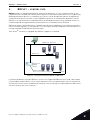
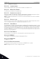
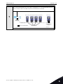
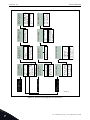
Figure 1. Principal example diagram of BACnet
If you have problems related to BACnet, contact [email protected]. Send a description
of the problem and the drive's
Service Information
file. You can download the Service Information
file with the Vacon Live tool. In BACnet/IP networks, also send a log file captured with the Wireshark
tool that contains the error situation.
BACnet IP - Ethernet
Ethernet to
MS/TP
Router
Switch
BACnet IP
BACnet MS/TP
7061.emf

3
vacon • 6 BACnet technical data
Tel. +358 (0) 201 2121 • Fax +358 (0)201 212 205
3. BACNET TECHNICAL DATA
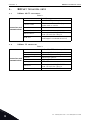
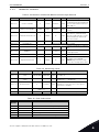
3.1 BACnet MS/TP protocol
3.2 BACnet IP protocol
Table 2.
Connections and
communications
Interface RS-485
Data transfer method RS-485 MS/TP, half-duplex
Transfer cable
STP (Shielded Twisted Pair), type
Belden 9841 or similar
Connector
2.5 mm
2
Electrical isolation Functional
BACnet MS/TP
As described in ANSI/ASHRAE Stan-
dards 135-2010 Ver.1 Rev.12
Baud rate
9600, 19200, 38400 and 76800
baud(supports autobaud detection)
Table 3.
Connections and
communications
Interface 100BaseTX, IEEE 802.3 compatible
Data transfer method Ethernet half/full -duplex
Data transfer speed 10/100 MBit/s, autosensing
Protocol BACnet over UDP/IP
Connector Shielded RJ45 connector.
Cable type CAT5e STP
BACnet IP
As described in ANSI/ASHRAE Stan-
dards 135-2010 Ver.1 Rev.12
IP address mode Selectable: Static or DHCP

Programming vacon • 7
24-hour support +358 (0)201 212 575 • Email: vac[email protected]
4
4. PROGRAMMING
You will find basic information on how to use the control keypad in the Application Manual of your
Vacon
®
100 drive.
Below you will find some examples of navigation paths to the fieldbus parameters.
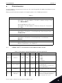
4.1 BACnet MS/TP parameters and monitoring values
Table 4.
1. First ensure that the right fieldbus protocol is selected.
Activating BACnet MSTP (P5.8.1.1)
Main Menu > I/O and Hardware > RS-485 > Common settings > Proto-
col > BACnet MSTP <
Activating BACnet IP (P5.9.3.1.4)
Main Menu > I/O and Hardware > Ethernet > Bacnet IP > Protocol in
use > Yes <
2. Select
‘Fieldbus control’ as the Remote Control Place.
Control Place (P3.2.1)
Main Menu > Parameters > Start/Stop Setup > Rem Control Place >
FieldbusCTRL <
3. Activate Remote control.
Local/Remote (P3.2.2)
Main Menu > Parameters > Start/Stop Setup > Local/Remote >
Remote <
4. Set up Protocol Parameters.
BACnet MS/TP parameters see Chapter 4.1
BACnet IP parameters see Chapter 4.2
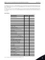
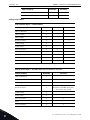
Table 5. Parameters related with BACnet used through MS/TP
Code Parameter Min Max Default ID Description
P5.8.3.1.1 Baud rate 9600 76800 9600 2392
Communication speed
1 = 9600
2 = 19200
3 = 38400
4 = 76800
5 = Autobaud
P5.8.3.1.2 MAC Address 1 127 1 2331 BACnet device MAC address
P5.8.3.1.3 Instance number 0 4194304 automatic 2332
Device Object's instance number.
0 = Automatically
generated from the last 22 bit from
Ethernet MAC address.
P5.8.3.1.4 MaxMaster 1 127 127 2561
Max Master parameter of device object.
This can be used to reduce poll for mas-
ter cycles.
P5.8.3.1.5
Communication
time-out
0 65535 10 2333
Defines the number of seconds after
which a communication timeout is indi-
cated after a communication break.
Value 0 disables this feature.

4
vacon • 8 Programming
Tel. +358 (0) 201 2121 • Fax +358 (0)201 212 205
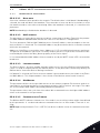
4.2 BACnet IP parameters and monitoring values
4.2.1 Ethernet common settings
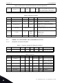
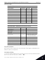
P5.8.3.1.6 MaxAPDUcycle 0 65535 0 2554
Defines the number of seconds after
which the next application level mes-
sage is shown after a communication
break. Value 0 disables this feature.
Table 6. Monitoring values
Code Parameter Min Max ID Description
P5.8.3.2.1 Fieldbus protocol status INITIALIZING INACTIVE 2393 See Table 12
P5.8.3.2.2 Communication status 0.0 99.999 2394
Counter for failed and good messages
failed msg's <-> good msg's
P5.8.3.2.3 Actual instance 0 4194304 2395
Actual instance in use. If the instance
parameter is 0, the generated instance
number shows here.
P5.8.3.2.4 Last fault
See fault codes
(table Table 11) 2396 Information about the latest fault detected.
P5.8.3.2.5 UartDBG 0.0.0
32767.
32767.
32767
2559
Uart error counters in the following order:
framing errors.
overrun errors.
parity errors.
P5.8.3.2.6 ActiveCOVcount 0 20 2558 Number of active COV subscriptions
Table 7. Common settings for Ethernet Interface
Code Parameter Min Max Unit Default ID Description
P5.9.1.1 IP address mode 0 1 1 2482
0 = Fixed IP
1 = DHCP with AutoIP
Table 8. Fixed IP
Code Parameter Min Max Unit Default ID Description
P5.9.1.2.1 IP address 192.168.0.10 2529
The parameter is in use
if P5.9.1.1 = 0/Fixed IP
P5.9.1.2.2 Subnet mask 255.255.0.0 2530
The parameter is in use
if P5.9.1.1 = 0/Fixed IP
P5.9.1.2.3 Default gateway 192.168.0.1 2531
The parameter is in use
if P5.9.1.1 = 0/Fixed IP
P5.9.1.3 IP address 0 2483 IP address in use
P5.9.1.4 Subnet mask 0 2484 Subnet mask in use
P5.9.1.5 Default gateway 0 2485 Default gateway in use
P5.9.1.6 MAC address 2486 MAC address
Table 5. Parameters related with BACnet used through MS/TP

Programming vacon • 9
24-hour support +358 (0)201 212 575 • Email: vac[email protected]
4
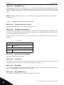
4.2.2 BACnet IP settings
Table 9. Parameters related with BACnet used through Ethernet
Code Parameter Min Max Default ID Description
P5.9.3.1.1 Instance number 0 4194304 automatic 2406
Device Object’s instance
0 = Automatically generated from
the last 22 bit from the Ethernet
MAC address.
P5.9.3.1.2 BACnet Port Number 47808 47823 47808 2538
UDP port for BACnet IP commu-
nication.
P5.9.3.1.2 Communication time-out 0 65535 10 2407
Defines the number of seconds
after which a communication
timeout is indicated after a com-
munication break. Value 0 dis-
ables this feature.
P5.9.3.1.3 Protocol in use 0 1 0 2408 Activates BACnet IP protocol
P5.9.3.1.4 ForeignDevice Sub menu for Foreign Device setting
P5.9.3.1.5.1 ForeignDevice No Yes No 2555
Activates foreign device registra-
tion
P5.9.3.1.5.2 BBMD IP 192.168.0.1 2409
IP address of BBMD device to
send registration
P5.9.3.1.5.3 BBMD Port 47808 47823 47808 2410 BBMD port number
P5.9.3.1.5.4 RegistrationInterval 1 65535 10 2411
Registration interval to keep a
live connection to BBMD.
NOTE! Registration message
TTL is twice as long as this time.
Table 10. Monitoring values
Code Parameter Min Max ID Description
P5.9.3.2.1
Fieldbus protocol
status
INITIALIZING INACTIVE 2412 See Table 12
P5.9.3.2.2
Communication
status
0.0 99.999 2413
Counter for failed and good messages
failed msg's <-> good msg's
P5.9.3.2.3 Actual instance 0 4194304 2414
Actual instance is use. In case instance
parameter is zero you can see here gener-
ated instance number
P5.9.3.2.4 Last fault
See fault codes
(Table 11)
2556 The fault code of the latest fault detected.
P5.9.3.2.5 ActiveCOVcount 0 20 2557 Number of active COV subscriptions
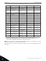
Table 11. Fault Code values
Fault
Number
Fault Text Description
0 No fault No fault detected since the last power-up.
1 Connection timeout Timeout occurred in communication.
2 MAC address Duplicate MAC address detected.
3 Autobaud Error Error during baudrate detection.
4 Ethernet link lost Ethernet cable disconnected during communication.

4
vacon • 10 Programming
Tel. +358 (0) 201 2121 • Fax +358 (0)201 212 205
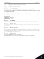
Table 12. Fieldbus Protocol Status
Value Text Description
1 INITIALIZING Protocol is starting
2 STOPPED Protocol is stopped
3 OPERATIONAL Communicating
4 FAULTED Timeout/APDU time expired
5 INACTIVE No communication

Programming vacon • 11
24-hour support +358 (0)201 212 575 • Email: vac[email protected]
4
4.3 BACnet MS/TP parameter descriptions
4.3.1 BACnet MS/TP Parameters
P5.8.3.1.1 B
AUD RATE
Select the communication speed for the network. The default value is 9600 baud. If Autobauding is
selected, the node will detect the baudrate. There must be at least one device in the bus to select
the baud rate and to start token transmitting. When the baudrate is detected, it is saved into this
parameter.
NOTE! Autobauding is disabled after baudrate is detected.
P5.8.3.1.2 MAC
ADDRESS
The parameters of every device must be set before connecting to the bus. Especially the parame-
ters
MAC address and Baud rate must be the same as in the master’s configuration.
The first parameter, BACnet MAC (Medium Access Control) address, must be unique on the net-
work to which it is connected. The same MAC address may be used on a device on another network
within the internetwork.
Addresses 128-254 are reserved for slaves. Addresses 1-127 are valid for both masters and slaves.
The portion of the address space that is actually used for masters in a particular installation is de-
termined by the value of the Max_Master property of the Device object.
It is recommended that MAC address 0 be reserved for use by the MS/TP router. 255 is reserved for
broadcasts.
P5.8.3.1.3 I
NSTANCE NUMBER
The Device Object's Instance number must be unique across the entire BACnet internetwork be-
cause it is used to uniquely identify the BACnet devices. It may be used to conveniently identify the
BACnet device from other devices during installation.
If 0 (default) is selected, the Device Instance number is generated from the last 22 bit of the Ether-
net MAC address. This unique number is then shown in the Monitor menu (actual instance).
P5.8.3.1.4 M
AXMASTER
This parameter defines the last possible master on the network segment. Each master node is re-
sponsible for searching new devices from network using the ‘poll for master’ messages. The nodes
are searched up to MAC address defined by MaxMaster parameter.
This parameter affects the cycle time of the token. We recommend to use the highest MAC address
value in the network for this parameter.
P5.8.3.1.5 C
OMMUNICATION TIMEOUT
The BACnet MS/TP indicates timeout error if the node is not receiving a token within time defined
by this parameter. It can be used to detect communication loss to other nodes. Time unit is sec-
onds.
NOTE! Application parameter P3.9.1.6 (ID 733) can be use to define action for communication time-
out.

4
vacon • 12 Programming
Tel. +358 (0) 201 2121 • Fax +358 (0)201 212 205
P5.8.3.1.6 MAXAPDUCYCLE
This parameter defines the maximum time in seconds between APDU messages addressed to this
node. The APDU messages are Application layer messages, for example, 'ReadParameter' and
'Write Parameter' messages. This can be used to detect communication loss to the controlling
node.
NOTE! The application parameter P3.9.1.6 (ID 733) can be used to define the action for communica-
tion timeout.
4.3.2 BACnet MS/TP monitoring values
P5.8.3.2.1 F
IELDBUS PROTOCOL STATUS
Fieldbus Protocol Status tells the status of the protocol.
P5.8.3.2.2 C
OMMUNICATION STATUS
The Communication status shows how many error and how many good messages the AC drive has
received. The Communication status includes a common error counter that counts CRC and parity
errors and a counter for good messages.
Only messages to the current slave in use are counted in the good messages, not MS/TP token
packages.
P5.8.3.2.3 A
CTUAL INSTANCE NUMBER
Shows the actual instance number.
P5.8.3.2.4 L
AST FAULT
This monitor value consist of text string that gives extra information about the fault condition. Can
be used to track the reason for communication timeout. See Table 11.
P5.8.3.2.5 U
ARTDBG
This is advanced debug information from RS-485 uart module. It shows parity, framing and overrun
errors occurred while receiving the MSTP messages.
P5.8.3.2.6 A
CTIVECOVCOUNT
This shows the number of active COV subscriptions on the device.
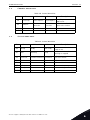
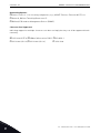
Table 13.
Good messages
0…999
Number of messages received with-
out errors
Bad Frames
0…99
Number of messages received with
errors

Programming vacon • 13
24-hour support +358 (0)201 212 575 • Email: vac[email protected]
4
4.4 BACnet IP parameter descriptions
4.4.1 Ethernet common settings
P5.9.1.1 IP
ADDRESS MODE
Selectable alternatives are DHCP (Dynamic Host Configuration Protocol) and Fixed.
DHCP protocol gives IP addresses to new devices connecting to local network. This address is valid
for a certain period of time.
A fixed IP address is specified manually and it does not change.
If the fixed IP mode is selected, the addresses defined in the 'Fixed IP' menu come into use. The
default Fixed IP is shown below.
IP: 192.168.0.10
Subnet mask: 255.255.0.0
Default gateway: 0.0.0.0
P5.9.1.3 IP
ADDRESS
An IP address is a series of numbers (like above) specific to the device connected to the Internet.
P5.9.1.4 S
UBNET MASK
The network mask marks all the bits of an IP address for the identification of the network and the
subnetwork.
P5.9.1.5 D
EFAULT GATEWAY
Gateway address is the IP address of a network point that acts as an entrance to another network.
This needs to be defined if the device communicates with nodes on different networks, for example,
if the 'Foreign Device' functionality is active.
P5.9.1.6 MAC
ADDRESS
The Ethernet MAC address of the control board.
MAC address (Media Access Control) is a unique address given to each network host.

4
vacon • 14 Programming
Tel. +358 (0) 201 2121 • Fax +358 (0)201 212 205
4.4.2 BACnet IP settings
P5.9.3.1.1 I
NSTANCE NUMBER
Similar to BACnet MS/TP device object instance number (see Chapter 4.3.1).
P5.9.3.1.2 BAC
NET PORT NUMBER
The UDP port for the BACnet IP communication.
P5.9.3.1.3 C
OMMUNICATION TIME-OUT
Defines the number of seconds after a timeout is indicated after a communication break or discon-
nected ethernet link. Value 0 disables communication and link supervision.
NOTE! The Application parameter P3.9.1.6 (ID 733) can be used to define the action for communi-
cation timeout.
P5.9.3.1.4 P
ROTOCOL IN USE
BACnet/IP protocol can be enabled and disabled with this parameter. When the parameter value is
set to "1" the BACnet/IP protocol is enabled and disabled when set to "0".
P5.9.3.1.5 F
OREIGNDEVICE
The foreign device settings are located under this submenu. The foreign device feature is used
when the device is located in a different network than the BBMD. A normal router does not send
broadcast messages between different networks. The 'Foreign device' feature solves this problem
by establishing a connection to the BBMD with unicast messages. All broadcast messages are for-
warded to a BBMD device that takes care of receiving and transmitting broadcast messages in both
directions for all foreign devices.
P5.9.3.1.5.1 F
OREIGNDEVICE
If this parameter is set to value 'Yes', the foreign device registration becomes active.
P5.9.3.1.5.2 BBMD IP
The IP address of the BACnet IP Broadcast Management Device.
P5.9.3.1.5.3 BBMD P
ORT
The BBMD Port number.
P5.9.3.1.5.4 R
EGISTRATIONINTERVAL
The registration interval to keep a live connection to the BBMD. Unit is seconds.
NOTE! The Registration TTL is twice as long as this time.

Programming vacon • 15
24-hour support +358 (0)201 212 575 • Email: vac[email protected]
4
4.4.3 BACnet IP monitoring values
P5.9.3.2.1 F
IELDBUS PROTOCOL STATUS
Fieldbus Protocol Status tells the status of the protocol.
P5.9.3.2.2 C
OMMUNICATION STATUS
The Communication status shows how many error and how many good messages the AC drive has
received. The Communication status includes a common error counter that counts CRC and parity
errors and a counter for good messages.
P5.9.3.2.3 A
CTUAL INSTANCE NUMBER
The Device Object's actual instance number. This monitoring value is needed when value 0 is writ-
ten to parameter P5.8.3.1.1.
P5.9.3.2.4 L
AST FAULT
This monitor value contains a text string that gives extra information about the fault condition. Can
be used to track reason for communication timeout. See Table 11.
P5.9.3.2.5 A
CTIVECOVCOUNT
This shows the number of active COV subscriptions on the device.
Table 14.
Good messages
0…999
Number of messages received with-
out errors
Bad Frames
0…99
Number of messages received with
errors

5
vacon • 16 Installation
Tel. +358 (0) 201 2121 • Fax +358 (0)201 212 205
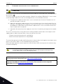
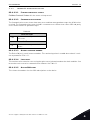
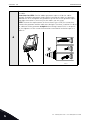
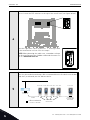
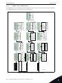
5. INSTALLATION
5.1 Vacon
®
100
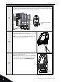
1
Open the cover of the AC drive.
The relay outputs and other I/O-terminals may have a dangerous control voltage
present even when the AC drive is disconnected from mains.
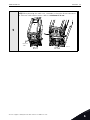
2
Open the inner cover of the drive.
M4x55
9174.emf
9000.emf

Installation vacon • 17
24-hour support +358 (0)201 212 575 • Email: vac[email protected]
5
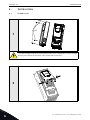
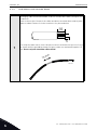
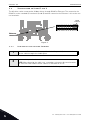
5.1.1 Prepare for use through Ethernet
3
Connect the Ethernet cable (see specification in Chapter 3.2) to its terminal as
shown in figure below.
Ethernet
cable
9316.emf

5
vacon • 18 Installation
Tel. +358 (0) 201 2121 • Fax +358 (0)201 212 205
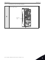
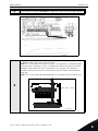
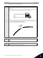
4
Protection class IP21: Cut free the opening on the AC drive cover for the Ether-
net cable.
Protection class IP54: Cut the rubber grommets open to slide the cables
through. Should the grommets fold in while inserting the cable, just draw the
cable back a bit to straighten the grommets up. Do not cut the grommet open-
ings wider than what is necessary for the cables you are using.
NOTE! To meet the requirements of the enclosure class IP54, the connection
between the grommet and the cable must be tight. Therefore, lead the first bit of
the cable out of the grommet straight before letting it bend. If this is not possi-
ble, the tightness of the connection must be ensured with insulation tape or a
cable tie.
9068.emf
Page is loading ...
Page is loading ...
Page is loading ...
Page is loading ...
Page is loading ...
Page is loading ...
Page is loading ...
Page is loading ...
Page is loading ...
Page is loading ...
Page is loading ...
Page is loading ...
Page is loading ...
Page is loading ...
Page is loading ...
Page is loading ...
Page is loading ...
Page is loading ...
Page is loading ...
Page is loading ...
Page is loading ...
Page is loading ...
Page is loading ...
Page is loading ...
-
 1
1
-
 2
2
-
 3
3
-
 4
4
-
 5
5
-
 6
6
-
 7
7
-
 8
8
-
 9
9
-
 10
10
-
 11
11
-
 12
12
-
 13
13
-
 14
14
-
 15
15
-
 16
16
-
 17
17
-
 18
18
-
 19
19
-
 20
20
-
 21
21
-
 22
22
-
 23
23
-
 24
24
-
 25
25
-
 26
26
-
 27
27
-
 28
28
-
 29
29
-
 30
30
-
 31
31
-
 32
32
-
 33
33
-
 34
34
-
 35
35
-
 36
36
-
 37
37
-
 38
38
-
 39
39
-
 40
40
-
 41
41
-
 42
42
-
 43
43
-
 44
44


Vacon 100 Industrial Installation guide
- Type
- Installation guide
- This manual is also suitable for
Ask a question and I''ll find the answer in the document
Finding information in a document is now easier with AI
Related papers
-
Vacon 100X series User manual
-
-
Vacon 100 Industrial Installation and User Manual
-
-
Vacon VACON 100 X Installation guide
-
-
-
Vacon 100 FLOW User manual
-
-
Other documents
-
Intronics EA9003 Datasheet
-
Sinclair SBG-01 User manual
-
Moxa MGate 5217 Series User guide
-
Danfoss VACON 20 X User guide
-
aci BACnet Outside Series Installation & Operation Instructions
-
LumenRadio W-BACnet User manual
-
-
Legrand LCAP32M Installation guide
-
olympia electronics GR-7500 User manual
-
Lennox CORE Unit Controller BACNet Installation guide