Nova Natural NOVA-7820 User manual
- Category
- Motherboards
- Type
- User manual

NOVA-7820
VIA
®
C3 Processor CPU
Embedded Board
with 10/100Mbps Ethernet, VGA,
Audio
Version 1.0
Manual Version 1.1
Jul 16, 2003
©Copyright 2003 by ICP Electronics Inc. All Rights Reserved.

2
Copyright Notice
The information in this document is subject to change without prior notice in
order to improve reliability, design and function and does not represent a
commitment on the part of the manufacturer. In no event will the manufacturer
be liable for direct, indirect, special, incidental, or consequential damages arising
out of the use or inability to use the product or documentation, even if advised of
the possibility of such damages.
This document contains proprietary information protected by copyright. All rights
are reserved. No part of this manual may be reproduced by any mechanical,
electronic, or other means in any form without prior written permission of the
manufacturer.
Trademarks
NOVA-7820 is registered trademarks of ICP Electronics Inc., IBM PC is a
registered trademark of International Business Machines Corporation. Intel is a
registered trademark of Intel Corporation. Award is registered trademarks of
Award Software International, Inc. Other product names mentioned herein are
used for identification purposes only and may be trademarks and/or registered
trademarks of their respective companies.
Support
Any questions regarding the content of this manual or related issues can be e-
mailed to us directly at: [email protected]
.

3
Table of Contents
1. Introduction .................................................................. 5
1.1 Specifications ..................................................................................5
1.2 Package Contents ............................................................................6
2. Installation.................................................................... 7
2.1 NOVA-7820 Layout ..........................................................................7
2.2 Clear CMOS Setup ............................................................................9
2.3 Compact Flash Setting .....................................................................9
2.4 Audio Amplifier Select .....................................................................9
2.5 LCD Panel Shift Clock/Panel VCC Select.........................................10
2.6 COM Port RI and Voltage Selection................................................10
2.7 COM4 RS232/RS422(485) Selection..............................................11
3. Connection .................................................................. 12
3.1 Floppy Disk Drive Connector..........................................................13
3.2 Video-in Connector ........................................................................13
3.3 Ultra ATA33/66/100 IDE Disk Drive Connector.............................14
3.4 Parallel Port...................................................................................14
3.5 USB Port Connector .......................................................................15
3.6 Serial Ports....................................................................................15
3.7 Power Connector ...........................................................................16
3.8 Keyboard Connector ......................................................................17
3.9 IrDA Infrared Interface Port..........................................................17
3.10 Fan Connector.............................................................................17
3.11 Audio Connectors........................................................................18
3.12 VGA Connector............................................................................18
3.13 LAN RJ45 Connector....................................................................19
3.14 Compact Flash Connector-TYPE II ..............................................19
3.15 External Switches and Indicators................................................20
3.16 IEEE-1394 Connector..................................................................20
3.17 CardBus/PCMCIA Connector .......................................................21
3.18 Digital I/O ..................................................................................22
3.19 LCD Panel Connector...................................................................23
4. AMI BIOS Setup........................................................... 24
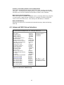
4.1 Introduction ..................................................................................24
4.2 Starting Setup................................................................................24
4.3 Setup Summary .............................................................................24
4.4 Standard CMOS Setup Selections...................................................26
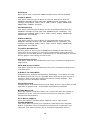
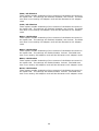
4.5 Advanced CMOS Setup Selections..................................................27
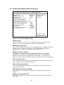
4.6 Advanced Chipset Setup Selections ...............................................31
4.7 Power Management Setup Selections ............................................33
4.8 PCI / Plug and Play Setup Selections.............................................35
4.9 Peripheral Setup Selections...........................................................37
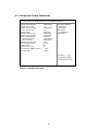
4.10 Hardware Monitor Setup Selections ............................................39
Appendix A Watchdog Timer .............................................. 40
Appendix B Digital I/O ....................................................... 41
Appendix C Address Mapping ............................................. 42
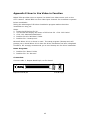
Appendix D How to Use Wake-up Function......................... 44

4
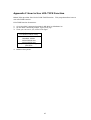
Appendix E How to Use Video-in Function ......................... 45
Appendix F How to Use LCD-TYPE Function........................ 47

5
1. Introduction
Thank you for choosing NOVA-7820 VIA
®
C3 Processor CPU with Multimedia
& LAN Ethernet Embedded Little Board, which comes equipped with Low
power VIA
®
C3 Processor CPU with the Intel advanced chipset 815E. This
product is designed for the system manufacturers, integrators, or VARs that
want to build a low power consumption system.
NOVA-7820 provides on-chip VGA which provides up to 1600 x 1200
resolution. LCD which provides up to 1024 x 768 resolution.
An advanced high performance super I/O chip – W83627 and NS87366 is
used in the NOVA-7820 board. Which provide four UARTs are compatible
with the NS16C550. The parallel port and FDD interface are compatible with
IBM PC/AT architecture's.
The NOVA-7820 has one Fast Ethernet Multifunction PCI Controller as a LAN
controller, Which are fully integrated 10BASE-T/100BASE-TX LAN solution
with high performance networking functions and low power features.
This board has a built-in Compact Flash Disk Socket, CardBus, FireWire for
embedded applications.
For multimedia application, NOVA-7820 provides many function, such as
1394 ,5.1 channel Audio and video in.
1.1 Specifications
• CPU: VIA
®
C3 Processor CPU
• DMA channels: 7
• Interrupt levels: 15
• Chipset: Intel 815E
• Memory: One 168-pin DIMM sockets. The memory capability is up to
512MB/133MHz.
• Ultra ATA/33/66/100 IDE Interface: One PCI Enhanced IDE channels (2
IDE devices). The south bridge ICH2 supports Ultra ATA/33/66/100 IDE
interface. To support Ultra ATA66/100 Hard disk, a specific cable
(maximum length — 45 cm) is available.
• Floppy disk drive interface: Single 2.88 MB, 1.44MB, 1.2MB, 720KB, or
360KB floppy disk drive.
• Serial ports: Four high-speed 16C550 compatible UARTs with 16-byte
FIFO buffer. Up to 115 Kbps in speed. And one port supports
RS232/422/485 function.
• Parallel Port: One IEEE1284 compatible Bi-directional ports. Supports
SPP/ECP/EPP.
• IrDA: Supports Serial Infrared(SIR) and Amplitude Shift Keyed
IR(ASKIR) interface.
• USB: Supports two USB 1.1 compatible ports.
• Audio: Onboard CMI8738 chipset, Supports 5.1 channel sound, that
include LINEOUT, REAR, and CENTER/BASS.
• Watchdog timer: Software programmable — enable/disabled. Timer
interval is 1 ~ 255 seconds. System Reset will be generated when time
out.
• VGA Controller: Embedded VGA controller. Screen Resolution: up to

6
1600 x 1200 in 256 Colors at 85 Hz Refresh.
• LCD Controller: Onboard SP1015 LCD controller. Screen Resolution: up
to 1024 x 768 36bits.
• Intel 82801BA embedded LAN: IEEE 802.3u Auto-Negotiation support
for 10BASE-T/100BASE-TX. Fast back-to-back transmission support
with minimum interframe spacing. Connected to your LAN through
RJ45 connector.
• Keyboard Controller: 8042 compatible for keyboard and PS/2 mouse
• 4 Digital Inputs and 4 Digital Outputs.
• 4 Channels of composite video input.
• FireWire: TSB43AA22 provides the digital and analog transceiver
functions to implement a two-port node in a cable-based IEEE 1394.
Provides two P1394a fully compliant cable ports at 100/200/400
megabits per second (Mbits/s).
• CardBus: Compliant with CardBus/PCMCIA PC Card 95/97 standard
specification.
• Power Consumption: 5V/3.0A and 12V/0.22A, as running by VIA Eden
ESP 4000(400MHz) and 256MB SDRAM.
• Operating Temperature: 0 ~ 60 (CPU needs heatsink)
1.2 Package Contents
In addition to this User Manual, NOVA-7820 package includes the following
items:
• NOVA-7820 Mobile CPU bases Single board computer x 1
• FDD cable x 1
• HDD cable x 1
• Keyboard / Mouse adapter Y cable
• Two RS-232 serial ports and RS-232/422/485 serial port cable x 1
• Printer port cable x 1
• AUDIO ports cable x 1
• 4-channel composite video cable x 2
• IEEE-1394 cable x 1

7
2. Installation
Follow the instructions of installing NOVA-7820. Read the unpacking
information carefully before installation.
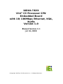
2.1 NOVA-7820 Layout

8

9
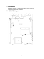
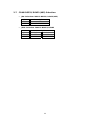
2.2 Clear CMOS Setup
CMOS RAM holds the configuration data of NOVA-7820, which has to be
set by means of system BIOS. To clear CMOS RAM, close JP1 for about 3
seconds, and then open it again. It will then resume to normal mode.
• JP1: Clear CMOS Setup
JP1 Description
1-2 Keep CMOS Setup
(Normal Operation)
2-3 Clear CMOS Setup
2.3 Compact Flash Setting
Set the operating mode of Compact Flash disk. This is similar to the
operation of hard disk.
• JP2: Compact Flash Setting
JP2 Description
OPEN Slave
Close Master
2.4 Audio Amplifier Select
This jumper is for the setting of Audio Amplifier.
• JP5: Audio L_Line out select
JP5 Description
1-2 OFF
2-3 ON
• JP6: Audio R_Line out select
JP6 Description
1-2 OFF
2-3 ON

10
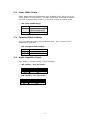
2.5 LCD Panel Shift Clock/Panel VCC Select
This jumper is for the setting of LCD panel shift clock mode and panel
power voltage.
• JP7: LCD Panel Shift Clock
JP7 Description
1-3 Inverted
3-5 Normal
• JP7: Panel VCC
JP7 Description
2-4 +5V
4-6 +3.3V
2.6 COM Port RI and Voltage Selection
JP8 is setting COM3, 4 RI and Voltage.
• JP8: Set pin 9 of COM3 as signal RI or voltage source
JP8 Description
10-12 COM3 RI Pin Use RI
8-10 COM3 RI Pin Use Voltage
• JP8: Set pin 9 of COM4 as signal RI or voltage source
JP8 Description
9-11 COM4 RI Pin Use RI
7-9 COM4 RI Pin Use Voltage
• JP8: Set pin 9 of COM3 as +5V or 12V
JP8 Description
2-4 COM3 RI Pin Use Voltage +5V
4-6 COM3 RI Pin Use Voltage +12V
• JP8: Set pin 9 of COM4 as +5V or 12V
JP8 Description
1-3 COM4 RI Pin Use Voltage +5V
3-5 COM4 RI Pin Use Voltage +12V

11
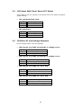
2.7 COM4 RS232/RS422(485) Selection
• JP9: Selection COM4 is RS232/RS422(485)
JP9 Description
1-2 RS232
2-3 RS422/485
• JP10: Selection COM4 is RS422/RS485
Description
JP10 1-3 2-4
RS422 OFF OFF
RS485 ON ON

12
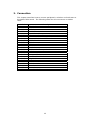
3. Connection
This chapter describes how to connect peripherals, switches and indicators to
the NOVA-7820 board. The following table lists the connectors on NOVA-
7820.
Label Description
CDIN1 CD-IN Connector
CN1 Parallel Port Connector
CN2 IDE Connector
CN7 SUS LED
CN8,11 Serial Port 1,2
CN12 ATX Power On/Off Button Connector
CN16 DIN Connector for Keyboard/Mouse
CN20 External Switch and Indicators
CN21,36 IEEE-1394 Connector
CN24 FDD Connector
CN26 ATX Power Connector
CN30 Power Connector
CN32 Audio Connector
CN33 4 Channels of composite video in Connector
CN35 USB Connector
CN37 LAN Connector
CN43 Compact Flash
CN44 CardBus/PCMCIA Connector
CN45 Digital I/O
CN47 LCD Connector
CN48,49 Serial Port 3,4
CON1 VGA Connector
FAN1,3 Fan Connectors
IR1 IrDA Connector
PCI1 Specific PCI Slot

13
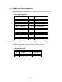
3.1 Floppy Disk Drive Connector
NOVA-7820 board is equipped with a 34-pin daisy-chain driver connector
cable.
• CN24: FDD Connector
PIN Description PIN Description
1 GROUND 2 REDUCE WRITE
3 GROUND 4 N/C
5 GROUND 6 DS1#
7 GROUND 8 INDEX#
9 GROUND 10 MOTOR ENABLE A#
11 GROUND 12 DRIVE SELECT B#
13 GROUND 14 DRIVE SELECT A#
15 GROUND 16 MOTOR ENABLE B#
17 GROUND 18 DIRECTION#
19 GROUND 20 STEP#
21 GROUND 22 WRITE DATA#
23 GROUND 24 WRITE GATE#
25 GROUND 26 TRACK 0#
27 GROUND 28 WRITE PROTECT#
29 N/C 30 READ DATA#
31 GROUND 32 SIDE 1 SELECT#
33 N/C 34 DISK CHANGE#
3.2 Video-in Connector
NOVA-7820 is equipped witch 4 channels of composite video
connector(BT878A).
• CN33: Capture IN
PIN Description PIN Description
1 AVIN0 2 GROUND
3 AVIN1 4 GROUND
5 AVIN2 6 GROUND
7 AVIN3 8 GROUND

14
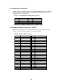
3.3 Ultra ATA33/66/100 IDE Disk Drive Connector
You can attach one IDE (Integrated Device Electronics) hard disk drives to
the NOVA-7820 IDE controller.
• CN2: Primary IDE Connector
PIN Description PIN Description
1 RESET# 2 GROUND
3 DATA 7 4 DATA 8
5 DATA 6 6 DATA 9
7 DATA 5 8 DATA 10
9 DATA 4 10 DATA 11
11 DATA 3 12 DATA 12
13 DATA 2 14 DATA 13
15 DATA 1 16 DATA 14
17 DATA 0 18 DATA 15
19 GROUND 20 N/C
21 N/C 22 GROUND
23 IOW# 24 GROUND
25 IOR# 26 GROUND
27 CHRDY 28 GROUND
29 DACK 30 GROUND
31 INTERRUPT 32 GROUND
33 SA1 34 P66DET
35 SA0 36 N/C
37 HDC CS0# 38 HDC CS1#
39 HDD ACTIVE# 40 GROUND
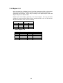
3.4 Parallel Port
This port is usually connected to a printer. NOVA-7820 includes an on-
board parallel port, and accessed through a 26-pin flat-cable connector
CN1. Three modes: SPP, EPP and ECP are supported.
• CN1: Parallel Port Connector
PIN Description PIN Description
1 STROBE# 14 AUTO FORM FEED #
2 DATA 0 15 ERROR#
3 DATA 1 16 INITIALIZE
4 DATA 2 17 PRINTER SELECT LN#
5 DATA 3 18 GROUND
6 DATA 4 19 GROUND
7 DATA 5 20 GROUND
8 DATA 6 21 GROUND
9 DATA 7 22 GROUND
10 ACKNOWLEDGE 23 GROUND
11 BUSY 24 GROUND
12 PAPER EMPTY 25 GROUND
13 PRINTER SELECT 26 N/C

15
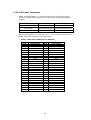
3.5 USB Port Connector
NOVA-7820 provides two USB ports (USB 1.1 compliant).
• CN35: USB 8-PIN HEADER
PIN Description
A1 VCC
A2 DATA0-
A3 DATA0+
A4 GROUND
B1 VCC
B2 DATA0-
B3 DATA0+
B4 GROUND
3.6 Serial Ports
NOVA-7820 offers four high speed NS16C550 compatible UARTs with
Read/Receive 16 byte FIFO in each serial port.
• CN8: D_SUB 9-PIN Connector
PIN Description
1 DATA CARRIER DETECT (DCD)
2 RECEIVE DATA (RXD)
3 TRANSMIT DATA (TXD)
4 DATA TERMINAL READY (DTR)
5 GROUND
6 DATA SET READY (DSR)
7 REQUEST TO SEND (RTS)
8 CLEAR TO SEND (CTS)
9 RING INDICATOR (RI)
• CN11: 10-pin Connector
PIN Description
1 DATA CARRIER DETECT (DCD)
2 RECEIVE DATA (RXD)
3 TRANSMIT DATA (TXD)
4 DATA TERMINAL READY (DTR)
5 GROUND
6 DATA SET READY (DSR)
7 REQUEST TO SEND (RTS)
8 CLEAR TO SEND (CTS)
9 RING INDICATOR (RI)
10 N/C

16
• CN48: 10-pin Connector
PIN Description
1 DATA CARRIER DETECT (DCD)
2 RECEIVE DATA (RXD)
3 TRANSMIT DATA (TXD)
4 DATA TERMINAL READY (DTR)
5 GROUND
6 DATA SET READY (DSR)
7 REQUEST TO SEND (RTS)
8 CLEAR TO SEND (CTS)
9 RING INDICATOR (RI)
10 N/C
• CN49: 14-pin Connector
PIN Description
1 DATA CARRIER DETECT (DCD)
2 RECEIVE DATA (RXD)
3 TRANSMIT DATA (TXD)
4 DATA TERMINAL READY (DTR)
5 GROUND
6 DATA SET READY (DSR)
7 REQUEST TO SEND (RTS)
8 CLEAR TO SEND (CTS)
9 RING INDICATOR (RI)
10 N/C
11 TX+ (RS422/485)
12 TX- (RS422/485)
13 RX+ (RS422/485)
14 RX- (RS422/485)
3.7 Power Connector
NOVA-7820 has one power connector for power supply.
• CN30: Power Supply Connector
PIN Description
1 VCC12V
2
GROUND
3
GROUND
4 VCC5V
• CN26: ATX Power Connector
PIN Description
1 VCC5VSB
2 PS_ON
3 GROUND

17
3.8 Keyboard Connector
NOVA-7820 provides 6-PIN MIN-DIN keyboard/mouse connector.
• CN16: 6-pin Mini-DIN Keyboard/Mouse Connector
PIN Description
1 KEYBOARD DATA
2 MOUSE DATA
3 GROUND
4 +5V
5 KEYBOARD CLOCK
6 MOUSE CLOCK
3.9 IrDA Infrared Interface Port
NOVA-7820 has a built-in IrDA port which supports Serial Infrared (SIR) or
Amplitude Shift Keyed IR (ASKIR) interface. To use the IrDA port, set SIR
or ASKIR model in COM 2 of BIOS Peripheral Setup. Then the normal RS-
232 COM 2 will be disabled.
• IR1: IrDA Connector
PIN Description
1 VCC5V
2 N/C
3 IR-RX
4 GROUND
5 IR-TX
3.10 Fan Connector
NOVA-7820 provides CPU cooling fan connector and system fan connector.
CPU connectors can supply 12V/500mA. The Fan’s rotation is in full speed.
• FAN1, FAN3: Fan Connector
PIN Description
1 SENSOR
2 12V
3 GROUND

18
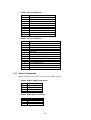
3.11 Audio Connectors
NOVA-7820 has a built-in AUDIO chipset (CMEDIA CMI8738LX); connector
directly connects to the pin-header (CN32). The audio chipset can support
5.1 channel sounds that include LINE-OUT, REAR, and CENTER/BASS.
• CN32: Audio Connector (2x8_2.00mm)
PIN Description PIN Description
1 LINEOUT_L 2 GROUND
3 LINEOUT_R 4 GROUND
5 CENTER 6 BASS
7 GROUND 8 GROUND
9 LININ_L 10 LINEIN_R
11 GROUND 12 GROUND
13 REAR_L 14 REAR_R
15 MIN_IN 16 GROUND
• CDIN1: CD-IN
PIN Description
1 CD LEFT SIGNAL
2 GROUND
3 GROUND
4 CD RIGHT SIGNAL
3.12 VGA Connector
NOVA-7820 has a built-in 15-pin VGA connector directly to your CRT
monitor.
• CON1: 15-pin Female Connector
PIN Description PIN Description
1 RED 2 GREEN
3 BLUE 4 N/C
5 GROUND 6 GROUND
7 GROUND 8 GROUND
9 VCC 10 GROUND
11 N/C 12 DDC DAT
13 HSYNC 14 VSYNC
15 DDCCLK

19
3.13 LAN RJ45 Connector
NOVA-7820 is equipped with built-in one 10/100Mbps Ethernet Controller.
You can connect it to your LAN through RJ45 LAN connector. The pin
assignments are as following:
• CN37 : Intel 82562ET LAN RJ45 Connector
PIN Description PIN Description
1 TX+ 5 N/C
2 TX- 6 RX-
3 RX+ 7 N/C
4 N/C 8 N/C
3.14 Compact Flash Connector-TYPE II
NOVA-7820 supports one Compact Flash socket that be provided from
IDE2. You must set the jumper to avoid the conflict.
• CN43: Compact Flash Socket
PIN Description PIN Description
1 GROUND 26 VCC-IN CHECK2
2 DATA3 27 DATA11
3 DATA4 28 DATA12
4 DATA5 29 DATA13
5 DATA6 30 DATA14
6 DATA7 31 DATA15
7 HDC_CS0# 32 HDC_CS1#
8 N/C 33 N/C
9 GROUND 34 IOR#
10 N/C 35 IOW#
11 N/C 36 N/C
12 N/C 37 INTERRUPT
13 +5V 38 +5V
14 N/C 39 CSEL
15 N/C 40 N/C
16 N/C 41 RESET#
17 N/C 42 IORDY
18 SA2 43 N/C
19 SA1 44 +5V
20 SA0 45 HDD_ACTIVE#
21 DATA0 46 N/C
22 DATA1 47 DATA8
23 DATA2 48 DATA9
24 N/C 49 DATA10
25 VCC-IN CHECK2 50 GROUND

20
3.15 External Switches and Indicators
There are several external switches and indicators for monitoring and
controlling your CPU board. All the functions are in the CN7, CN12, and
CN20 connectors.
• Suspend Led Connector (CN7)
PIN Description
1 LED+
2 LED-
• ATX Power On/Off Button Connector (CN12)
PIN Description
1 PWR_BUTTON+
2 GROUND
• CN20: Multi Panel
PIN Description PIN Description
1 POWER-LED + 2 SPEAKER -
3 N/C 4 N/C
5 POWER-LED - 6 N/C
7 KEYLOCK+ 8 SPEAKER +5V
9 KEYLOCK- 10 RESET SW
11 GROUND 12 RESET SW GND
13 HDD LED+ 14 HDD LED -
3.16 IEEE-1394 Connector
NOVA-7820 is equipped witch IEEE1394 controller (TI TSB43AA22). You
can connect it to your 1394 device through CN21, 36 connectors. The pin
assignments are as follows:
• CN21: 1394 Connector
PIN Description PIN Description
1 VCC12V 2 GROUND
3 TPB- 4 TPB+
5 TPA- 6 TPA+
7 NC/FG 8 NC/FG
• CN36: 1394 Connector
PIN Description PIN Description
1 VCC12V 2 GROUND
3 TPB- 4 TPB+
5 TPA- 6 TPA+
Page is loading ...
Page is loading ...
Page is loading ...
Page is loading ...
Page is loading ...
Page is loading ...
Page is loading ...
Page is loading ...
Page is loading ...
Page is loading ...
Page is loading ...
Page is loading ...
Page is loading ...
Page is loading ...
Page is loading ...
Page is loading ...
Page is loading ...
Page is loading ...
Page is loading ...
Page is loading ...
Page is loading ...
Page is loading ...
Page is loading ...
Page is loading ...
Page is loading ...
Page is loading ...
Page is loading ...
-
 1
1
-
 2
2
-
 3
3
-
 4
4
-
 5
5
-
 6
6
-
 7
7
-
 8
8
-
 9
9
-
 10
10
-
 11
11
-
 12
12
-
 13
13
-
 14
14
-
 15
15
-
 16
16
-
 17
17
-
 18
18
-
 19
19
-
 20
20
-
 21
21
-
 22
22
-
 23
23
-
 24
24
-
 25
25
-
 26
26
-
 27
27
-
 28
28
-
 29
29
-
 30
30
-
 31
31
-
 32
32
-
 33
33
-
 34
34
-
 35
35
-
 36
36
-
 37
37
-
 38
38
-
 39
39
-
 40
40
-
 41
41
-
 42
42
-
 43
43
-
 44
44
-
 45
45
-
 46
46
-
 47
47


Nova Natural NOVA-7820 User manual
- Category
- Motherboards
- Type
- User manual
Ask a question and I''ll find the answer in the document
Finding information in a document is now easier with AI

