Page is loading ...

omega.com
e-mail: [email protected]
For latest product manuals:
omegamanual.info
User’s Guide
M-4292/1006
PCL340 Series
Shop online at

Servicing North America:
USA: One Omega Drive, Box 4047
ISO 9001 Certified Stamford CT 06907-0047
Tel: (203) 359-1660 FAX: (203) 359-7700
e-mail: [email protected]
Canada: 976 Bergar
Laval (Quebec) H7L 5A1, Canada
Tel: (514) 856-6928 FAX: (514) 856-6886
e-mail: [email protected]
For immediate technical or application assistance:
USA and Canada: Sales Service: 1-800-826-6342 / 1-800-TC-OMEGA
®
Customer Service: 1-800-622-2378 / 1-800-622-BEST
®
Engineering Service: 1-800-872-9436 / 1-800-USA-WHEN
®
TELEX: 996404 EASYLINK: 62968934 CABLE: OMEGA
Mexico: En Espan˜ ol: (001) 203-359-7803 e-mail: [email protected]
FAX: (001) 203-359-7807 [email protected]
Servicing Europe:
Benelux: Postbus 8034, 1180 LA Amstelveen, The Netherlands
Tel: +31 (0)20 3472121 FAX: +31 (0)20 6434643
Toll Free in Benelux: 0800 0993344
e-mail: [email protected]
Czech Republic: Frystatska 184, 733 01 Karvina´, Czech Republic
Tel: +420 (0)59 6311899 FAX: +420 (0)59 6311114
Toll Free: 0800-1-66342 e-mail: [email protected]
France: 11, rue Jacques Cartier, 78280 Guyancourt, France
Tel: +33 (0)1 61 37 2900 FAX: +33 (0)1 30 57 5427
Toll Free in France: 0800 466 342
e-mail: [email protected]
Germany/Austria: Daimlerstrasse 26, D-75392 Deckenpfronn, Germany
Tel: +49 (0)7056 9398-0 FAX: +49 (0)7056 9398-29
Toll Free in Germany: 0800 639 7678
e-mail: [email protected]
United Kingdom: One Omega Drive, River Bend Technology Centre
ISO 9002 Certified Northbank, Irlam, Manchester
M44 5BD United Kingdom
Tel: +44 (0)161 777 6611 FAX: +44 (0)161 777 6622
Toll Free in United Kingdom: 0800-488-488
e-mail: [email protected]
OMEGAnet
®
Online Service Internet e-mail
www.omega.com [email protected]
It is the policy of OMEGA to comply with all worldwide safety and EMC/EMI regulations that
apply. OMEGA is constantly pursuing certification of its products to the European New Approach
Directives. OMEGA will add the CE mark to every appropriate device upon certification.
The information contained in this document is believed to be correct, but OMEGA Engineering, Inc. accepts
no liability for any errors it contains, and reserves the right to alter specifications without notice.
WARNING: These products are not designed for use in, and should not be used for, human applications.

1. Introduction . . . . . . . . . . . . . . . . . . . . . . . . . . . . . . . . . . . . . . . . . . . .1
1.1 Contacting OMEGA . . . . . . . . . . . . . . . . . . . . . . . . . . . . . . . . . . . . . . . .1
1.2 Standard Equipment . . . . . . . . . . . . . . . . . . . . . . . . . . . . . . . . . . . . . . .1
1.3 Safety Information . . . . . . . . . . . . . . . . . . . . . . . . . . . . . . . . . . . . . . . . .1
2. Calibrator Interface . . . . . . . . . . . . . . . . . . . . . . . . . . . . . . . . . . . . . .4
2.1 Calibrator Display . . . . . . . . . . . . . . . . . . . . . . . . . . . . . . . . . . . . . . . . .5
2.2 Using the Backlight . . . . . . . . . . . . . . . . . . . . . . . . . . . . . . . . . . . . . . . .9
2.3 Using the Zero Function . . . . . . . . . . . . . . . . . . . . . . . . . . . . . . . . . . . .9
2.4 Other Menu Controlled Functions . . . . . . . . . . . . . . . . . . . . . . . . . . . . .9
3. Measuring Pressure . . . . . . . . . . . . . . . . . . . . . . . . . . . . . . . . . . . . .12
3.1 Media Compatibility . . . . . . . . . . . . . . . . . . . . . . . . . . . . . . . . . . . . . . .12
3.2 Measuring Pressure with External Modules . . . . . . . . . . . . . . . . . . . . .12
4. Measuring Current . . . . . . . . . . . . . . . . . . . . . . . . . . . . . . . . . . . . . .13
5. Measuring Voltage . . . . . . . . . . . . . . . . . . . . . . . . . . . . . . . . . . . . . .14
6. Performing a Pressure Switch Test . . . . . . . . . . . . . . . . . . . . . . . . .15
7. Calibrating Transmitters . . . . . . . . . . . . . . . . . . . . . . . . . . . . . . . . .17
7.1 Using the mA Input Function . . . . . . . . . . . . . . . . . . . . . . . . . . . . . . . .17
7.2 Calibrating a Pressure-to-Current Transmitter . . . . . . . . . . . . . . . . . . . .18
7.3 Percent Error Function . . . . . . . . . . . . . . . . . . . . . . . . . . . . . . . . . . . . .18
8. Factory Setups . . . . . . . . . . . . . . . . . . . . . . . . . . . . . . . . . . . . . . . . .21
9. Remote Operation . . . . . . . . . . . . . . . . . . . . . . . . . . . . . . . . . . . . . .23
9.1 Remote Interface . . . . . . . . . . . . . . . . . . . . . . . . . . . . . . . . . . . . . . . .23
9.2 Setting up the RS-232 Port for Remote Control . . . . . . . . . . . . . . . . . .23
9.3 Changing Between Remote and Local Operation . . . . . . . . . . . . . . . .24
9.4 Using Commands . . . . . . . . . . . . . . . . . . . . . . . . . . . . . . . . . . . . . . . .24
9.5 Remote Commands and Error Codes . . . . . . . . . . . . . . . . . . . . . . . . .27
9.6 Entering Commands . . . . . . . . . . . . . . . . . . . . . . . . . . . . . . . . . . . . . .29
10. Specifications . . . . . . . . . . . . . . . . . . . . . . . . . . . . . . . . . . . . . . . . .35
11. Maintenance . . . . . . . . . . . . . . . . . . . . . . . . . . . . . . . . . . . . . . . . . .36
11.1 Replacing Batteries . . . . . . . . . . . . . . . . . . . . . . . . . . . . . . . . . . . . . .36
11.2 Cleaning the Unit . . . . . . . . . . . . . . . . . . . . . . . . . . . . . . . . . . . . . . . .36
11.3 Service Center Calibration or Repair . . . . . . . . . . . . . . . . . . . . . . . . .36


1. Introduction
The OMEGA PCL340 Series is designed to be a simple to use yet
very versatile pressure calibrator. Its internal pressure sensor
combined with inputs for mA, voltage and switch contacts allow the
PCL340 Series to calibrate a variety of pressure devices. An external
pressure module option allows an even wider range of pressure
calibration options including absolute and differential.
1.1 Customer Service
Omega Engineering
One Omega Drive
Box 4047
Stamford, CT 06907-0047
Tel: (203) 359-1660
Fax: (203) 359-7900
www.omega.com
email: [email protected]
1.2 Standard Equipment
Check to see if your calibrator is complete. It should include: PCL340
Series Calibrator, instruction manual, test leads, carrying case,
calibration certificate with data.
1.3 Safety information
Symbols Used
The following table lists the International Electrical Symbols. Some or
all of these symbols may be used on the instrument or in this
manual.
Symbol Description
AC (Alternating Current)
AC-DC
Battery
CE Complies with European Union Directives
DC
1

Symbol Description
Double Insulated
Electric Shock
Fuse
PE Ground
Hot Surface (Burn Hazard)
Read the User’s Manual (Important Information)
Off
On
The following definitions apply to the terms “Warning” and “Caution”.
• “Warning” identifies conditions and actions that may pose hazards
to the user.
• “Caution” identifies conditions and actions that may damage the
instrument being used.
Use the calibrator only as specified in this manual, otherwise injury
and damage to the calibrator may occur.
Warning
To avoid possible electric shock or personal injury:
• Do not apply more than the rated voltage. See specifications for
supported ranges.
• Follow all equipment safety procedures.
• Never touch the probe to a voltage source when the test leads are
plugged into the current terminals.
• Do not use the calibrator if it is damaged. Before you use the
calibrator, inspect the case. Look for cracks or missing plastic. Pay
particular attention to the insulation surrounding the connectors.
2

3
• Select the proper function and range for your measurement.
• Make sure the battery cover is closed and latched before you
operate the calibrator.
• Remove test leads from the calibrator before you open the battery
door.
• Inspect the test leads for damaged insulation or exposed metal.
Check test leads continuity. Replace damaged test leads before
you use the calibrator.
• When using the probes, keep your fingers away from the probe
contacts. Keep your fingers behind the finger guards on the
probes.
• Connect the common test lead before you connect the live test
lead. When you disconnect test leads, disconnect the live test lead
first.
• Do not use the calibrator if it operates abnormally. Protection may
be impaired. When in doubt, have the calibrator serviced.
• Do not operate the calibrator around explosive gas, vapor, or dust.
• When measuring pressure, make sure the process pressure line is
shut off and depressurized before you connect it or disconnect it
from the pressure module.
• Disconnect test leads before changing to another measure or
source function.
• When servicing the calibrator, use only specified replacement
parts.
• To avoid false readings, which could lead to possible electric shock
or personal injury, replace the battery as soon as the battery
indicator appears.
Caution
To avoid possible damage to calibrator or to equipment under test:
• Use the proper jacks, function, and range for your measurement or
sourcing application.

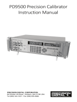
2. Calibrator Interface
Figure 1 shows the location of the process measurement inputs,
while table 1 describes their use.
Figure 1
Process Measurement Inputs
Table 1 Process Measurement Inputs
No. Name Description
1, 2 Input Terminals These terminals are used to
measure current, voltage and a
contact closure for switch test.
3 P1 Pressure Port This is the connection for the
internal sensor P1
4 Serial Interface This is used to interface to optional
external modules or optional serial
control.
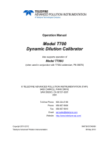
Figure 2 shows the location of the keys. Table 2 describes the
function of each key.
4
Side View

Figure 2
Keypad
Table 2 Key Functions
No. Name Description
1 Function Keys These keys are used in various ways, primarily to
configure the calibrator
2 ON/OFF Key This key is used to turn the calibrator on and off
3 ZERO Key This key is used to zero pressure measurements
4 Backlight Key This key is used to turn the backlight on and off
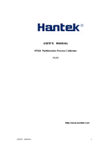
2.1 Calibrator Display
The Calibrator Display consists of two regions: The menu bar
(located along the bottom of the screen) is used to access a menu
system. The main display (the rest) consists of up to three process
measurement sub-regions. These sub-regions will henceforth be
referred to as the UPPER, MIDDLE and LOWER displays. Figure 3
shows the location of the different display fields while table 3
describes them.
5

6
Figure 3
Display
Table 3 Display Functions
No. Name Description
1 Primary Parameters Indicates what is being measured.
2 Span Indicator Indicates the percent of the 4 to 20 mA span.
(For mA and mA Loop functions only)
3 Pressure Units Indicates one of 17 pressure units available
for display.
4 Units Indicates the unit of measure for the display.
2.1.1 Main Menu Functionality
There are three options on the Main Menu, CONFIG, {current
display} and MORE. The Main Menu is home for the menu display.
2.1.1.1 Setting the Current Display
The current display is indicated by the center option on the Main
Menu, pressing the F2 key will toggle the current display.
2.1.1.2 Setting Current Display Parameters
To set the parameters of the current display use the CONFIG option
to get to the Display Configuration Menu.
Here the SELECT option will toggle through the choices for each
parameter. The first parameter is MODE. Since voltage, current and
switch test modes all use the same jacks, two of these functions
cannot be used concurrently. The ability to select certain functions is
limited based on what is already selected in another active display.
The NEXT option is used to change to the second parameter. Only
Pressure modes have a second parameter. Pressures can be read in
13 engineering units.

7
OTHER DISPLAYS
With a single display the following modes are available:
P[1] = Pressure on left side sensor.
[EXT] = Pressure with external pressure module.
P[1] ST = Switch Test with left side sensor.
[EXT] ST = Switch Test with external pressure module.
mA = Milliamps measure without loop power.
mA LOOP = Milliamps measure with loop power.
VOLTS = Voltage Measure.
The following table shows which functions are available concurrently.
An X in a column indicates that the mode in the current display will
not be available for selection if the mode in that row is in use in any
other active display.
Table 4 Mode Concurrency
CURRENT DISPLAY
P[1] [EXT] P[1] [EXT] mA mA Volts
ST ST Loop
P[1]
[EXT]
P[1]ST X X X X X
[EXT]ST X X X X X
mA X X X X
mA Loop X X X X
Volts X X X X
2.1.1.3 Accessing Other Menus
Use the MORE option on the Main Menu to access the other menu
functions.

8
Figure 4
Menu Map

9
2.2 Using the Backlight
The backlight is controlled by the dedicated backlight key. It toggles
on and off when the key is pressed; this is one of the few functions
that cannot be controlled by the serial interface.
2.3 Using the Zero Function
When the ZERO_KEY is pressed, the calibrator will zero the current
display if a pressure mode is selected, and the pressure is within the
zero limit.
2.3.1 Internal Sensor and Pressure Module (non-absolute)
When a sensor or module is selected on the current display and the
ZERO_KEY is pressed the calibrator subtracts the current reading
from the output.
2.3.2 Absolute Pressure Module
When an absolute pressure module is selected on the current
display and the ZERO_KEY is pressed the calibrator prompts the
user to enter the barometric reference pressure. This is done using
the arrow keys (F2 and F3 Keys).
2.4 Other Menu Controlled Functions
There are eight ‘sub-main’ menus that can be accessed through the
MORE option of the Main Menu. A ‘sub-main’ menu contains three
options. The first option is unique to the function. The second and
third options of a ‘sub-main’ menu are always the same. The NEXT
option leads to the next ‘sub-main’ menu and the DONE option
returns home . For the last ‘sub-main’ menu the NEXT option wraps
around to home. See Figure 4 for a detailed mapping of the menu
structure.
A note on naming convention:
If a ‘sub-main’ menu has subordinate menus, it will henceforth be
referred to as {function} Main Menu. E.g. the display contrast sub-
main menu will be called the Contrast Main Menu. If not it will be
called the {function} menu.

10
2.4.1 Setting the Contrast
From the Contrast Main Menu choose the CONTRAST option to
access the Contrast Adjustment Menu.
Use the arrow keys to adjust the display contrast to the desired level
and then use the CONTRAST DONE option to return home.
2.4.2 Locking and Unlocking Configurations
Use the LOCK CFG or UNLOCK CFG option of the Configuration
Lock Menu to lock or unlock the display configuration.
When the LOCK CFG option is chosen the menu display returns
home and the CONFIG option on the Main Menu indicates that it is
locked. Also all menus are locked out with the exception of the
Contrast Adjustment menus and the Configuration Lock Menu.
When the UNLOCK CFG option is chosen the configuration is
unlocked and the menu display continues to the next sub-main
menu.
2.4.3 Saving and Recalling Setups
The calibrator will automatically save the current set-up for recall at
power-up. Additionally 5 set-ups can be accessed through the
SETUPS menu. Select the SETUPS option from the Setups Main
Menu.
Choose SAVE to save a set-up , RECALL to recall the set-up, or
DONE to do nothing and return home.
If SAVE or RECALL is selected use the arrow keys to select the set-
up location. Then use the save option to store the current set-up into
the selected location or the recall option to recall the set-up stored in
the selected location. The display menu will automatically go home.

11
2.4.4 Setting AutoShut-off Parameters
The calibrator can be set to automatically shut-off after a selected
number of minutes; this function can also be disabled. To set the
auto shut off parameters select the AUTO OFF option on the Auto
Shut Off Main Menu.
Use the arrow keys to select the number of minutes before the
calibrator turns off or disable auto shut-off by scrolling all the way
down.
Use the AUTO OFF DONE option to set the parameters and return
home. The auto shut off time is reset whenever a key is pressed.
2.4.5 Activating and Deactivating a Display
Use the DISPLAY option on the Display Selection Main Menu to
access the Display Activation Menu.
The {function} option can be used to select which display to act
upon. The ON/OFF option turns the selected display on or off. The
selected display and current on/off state are displayed in the lower
display.
Use the DONE option to save the changes and return home. When
a display is deactivated its configuration is retained. When the
display is activated its configuration is checked against the

12
configurations of the other currently active displays, if the
configurations are in conflict the recalled display’s configuration is
modified to avoid the conflict. If all three displays are deactivated the
LOWER display will come on automatically
3. Measuring Pressure
To measure pressure, connect the calibrator using an appropriate
fitting. Choose a pressure setting for the display being used. The
calibrator is equipped with one internal sensor and many optional
external Pressure Modules are available. Be sure to choose the
sensor based on working pressures and accuracy.
Figure 5
Use the (ZERO) key to zero the pressure sensor when vented to
atmospheric pressure.
Important NOTE: To ensure accuracy of the calibrator it is critical
to zero the calibrator before a device is calibrated.
3.1 Media Compatibility
The calibrator utilizes a media isolated sensor to prevent sensor
contamination. Whenever possible clean, dry air is the media of
choice. If that is not always possible, make sure that the media is
compatible with Nickel Plated Brass, Silicon, RTV, glass, and ceramic
materials.
3.2 Measuring Pressure with External Modules
The calibrator provides a digital interface to External Pressure
Modules. These modules are available in various ranges and types

13
including gauge, vacuum, differential and absolute. The modules
work seamlessly with the calibrator. Simply plug them into the
interface and select [EXT] (external sensor). Since the interface
between the calibrator and the module is digital all the accuracy and
display resolution is derived from the module.
Figure 6
4. Measuring Current
To measure current use the input terminals in the front of the
calibrator. Select the mA function on one of the displays. Current is
measured in mA and percentage of range. The range on the
calibrator is set to 0% at 4 mA and 100% at 20 mA.
For example:
If the current measured is displayed as 75% then the mA value is 16
mA.

Figure 7
5. Measuring Voltage
To measure voltage use the input terminals in the front of the
calibrator. Select the Volts function on one of the displays. The
calibrator can measure up to 30V.
Figure 8
14

6. Performing a Pressure Switch Test
Figure 10
To perform a switch test, follow these steps:
1. Change the setup to Setup 4 (default switch test).
Setup 4: The upper display is set to [P1] ST, all other displays
are off.
Important NOTE: The pressure Switch Test can be performed
with the following functions[P1] ST, or EXT ST.
2. Connect the calibrator to the switch using the pressure switch
terminals. The polarity of the terminals does not matter. Then
connect the pump to the calibrator and the pressure switch.
3. Make sure the vent on the pump is open. Zero the calibrator if
necessary. Close the vent after zeroing the calibrator.
4. The top of the display will read “CLOSE”.
15
Pressure switch
under test

5. Apply pressure with the pump slowly until the switch opens.
Important NOTE: In the switch test mode the display update rate is
increased to help capture changing pressure inputs. Even with this
enhanced sample rate pressurizing the device under test should be
done slowly to ensure accurate readings.
6. Once the switch is open, “OPEN” will be displayed, bleed the
pump slowly until the pressure switch closes.
7. At the top of the display it will now read, “SW OPENED AT” and
give you the pressure that the switch opened at.
8. Press the “NEXT” option to view when the switch closed, and the
dead band.
16
/