
En
AV Receiver
TX-NR1000
TX-NR5000E
Instruction Manual
Thank you for purchasing an Onkyo AV Receiver.
Please read this manual thoroughly before making
connections and plugging in the unit.
Following the instructions in this manual will enable
you to obtain optimum performance and listening
enjoyment from your new AV Receiver.
Please retain this manual for future reference.
Contents
Getting Started 2
Installation and
Connections 18
Operations 48
Setup Menu 82
Using the Remote
Controller 124
Miscellaneous 143

2
Important Safety Instructions
1. Read these instructions.
2. Keep these instructions.
3. Heed all warnings.
4. Follow all instructions.
5. Do not use this apparatus near water.
6. Clean only with dry cloth.
7. Do not block any ventilation openings. Install in
accordance with the manufacturer’s instructions.
8. Do not install near any heat sources such as radia-
tors, heat registers, stoves, or other apparatus
(including amplifiers) that produce heat.
9. Do not defeat the safety purpose of the polarized or
grounding-type plug. A polarized plug has two
blades with one wider than the other. A grounding
type plug has two blades and a third grounding
prong. The wide blade or the third prong are pro-
vided for your safety. If the provided plug does not
fit into your outlet, consult an electrician for
replacement of the obsolete outlet.
10. Protect the power cord from being walked on or
pinched particularly at plugs, convenience recepta-
cles, and the point where they exit from the appara-
tus.
11. Only use attachments/accessories specified by the
manufacturer.
12.
Use only with the cart, stand,
tripod, bracket, or table spec-
ified by the manufacturer, or
sold with the apparatus.
When a cart is used, use cau-
tion when moving the cart/
apparatus combination to
avoid injury from tip-over.
13. Unplug this apparatus during lightning storms or
when unused for long periods of time.
14. Refer all servicing to qualified service personnel.
Servicing is required when the apparatus has been
damaged in any way, such as power-supply cord or
plug is damaged, liquid has been spilled or objects
have fallen into the apparatus, the apparatus has
been exposed to rain or moisture, does not operate
normally, or has been dropped.
15. Damage Requiring Service
Unplug the apparatus from the wall outlet and refer
servicing to qualified service personnel under the
following conditions:
A. When the power-supply cord or plug is damaged,
B. If liquid has been spilled, or objects have fallen
into the apparatus,
C. If the apparatus has been exposed to rain or
water,
D. If the apparatus does not operate normally by
following the operating instructions. Adjust only
those controls that are covered by the operating
instructions as an improper adjustment of other
controls may result in damage and will often
require extensive work by a qualified technician
to restore the apparatus to its normal operation,
E. If the apparatus has been dropped or damaged in
any way, and
F. When the apparatus exhibits a distinct change in
performance this indicates a need for service.
16. Object and Liquid Entry
Never push objects of any kind into the apparatus
through openings as they may touch dangerous volt-
age points or short-out parts that could result in a
fire or electric shock.
The apparatus shall not be exposed to dripping or
splashing and no objects filled with liquids, such as
vases shall be placed on the apparatus.
Don’t put candles or other burning objects on top of
this unit.
17. Batteries
Always consider the environmental issues and fol-
low local regulations when disposing of batteries.
18. If you install the apparatus in a built-in installation,
such as a bookcase or rack, ensure that there is ade-
quate ventilation.
Leave 20 cm (8") of free space at the top and sides
and 10 cm (4") at the rear. The rear edge of the shelf
or board above the apparatus shall be set 10 cm (4")
away from the rear panel or wall, creating a flue-like
gap for warm air to escape.
WARNING:
TO REDUCE THE RISK OF FIRE OR ELECTRIC
SHOCK, DO NOT EXPOSE THIS APPARATUS
TO RAIN OR MOISTURE.
CAUTION:
TO REDUCE THE RISK OF ELECTRIC SHOCK,
DO NOT REMOVE COVER (OR BACK). NO
USER-SERVICEABLE PARTS INSIDE. REFER
SERVICING TO QUALIFIED SERVICE
PERSONNEL.
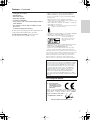
The lightning flash with arrowhead symbol, within an
equilateral triangle, is intended to alert the user to the
presence of uninsulated “dangerous voltage” within
the product’s enclosure that may be of sufficient
magnitude to constitute a risk of electric shock to
persons.
The exclamation point within an equilateral triangle is
intended to alert the user to the presence of important
operating and maintenance (servicing) instructions in
the literature accompanying the appliance.
WARNING
RISK OF ELECTRIC SHOCK
DO NOT OPEN
RISQUE DE CHOC ELECTRIQUE
NE PAS
OUVRIR
AVIS
PORTABLE CART WARNING
S3125A

3
Precautions
1. Recording Copyright
Unless it’s for personal use only, recording copyrighted
material is illegal without permission of the copyright
holder.
2. AC Fuse
The AC fuse inside the TX-NR1000/TX-NR5000E is not
user-serviceable. If you cannot turn on the TX-NR1000/
TX-NR5000E, contact your Onkyo dealer.
3. Care
Occasionally you should dust the TX-NR1000/
TX-NR5000E all over with a soft cloth. For stubborn
stains, use a soft cloth dampened with a weak solution of
mild detergent and water. Dry the TX-NR1000/
TX-NR5000E immediately afterwards with a clean cloth.
Don’t use abrasive cloths, thinners, alcohol, or other
chemical solvents, because they may damage the finish or
remove the panel lettering.
4. Power
WARNING
BEFORE PLUGGING IN THE UNIT FOR THE FIRST
TIME, READ THE FOLLOWING SECTION CAREFULLY.
AC outlet voltages vary from country to country. Make sure
that the voltage in your area meets the voltage requirements
printed on the TX-NR1000/TX-NR5000E’s rear panel (e.g.,
AC 230 V, 50 Hz or AC 120 V, 60 Hz).
The Worldwide model has a voltage selector for compatibility
with power systems around the world. Before you plug in this
model, make sure that the voltage selector is set to the correct
voltage for your area.
For USA, Canadian, and Australian models
Setting the [STANDBY/ON] switch to STANDBY does not
fully shutdown the TX-NR1000/TX-NR5000E. If you do not
intend to use the TX-NR1000/TX-NR5000E for an extended
period, remove the power cord from the AC outlet.
For British Models
Replacement and mounting of an AC plug on the power supply
cord of this unit should be performed only by qualified service
personnel.
IMPORTANT
The wires in the mains lead are coloured in accordance with
the following code:
Blue: Neutral
Brown: Live
As the colours of the wires in the mains lead of this apparatus
may not correspond with the coloured markings identifying the
terminals in your plug, proceed as follows:
The wire that is coloured blue must be connected to the termi-
nal that is marked with the letter N or coloured black.
The wire that is coloured brown must be connected to the ter-
minal that is marked with the letter L or coloured red.
IMPORTANT
The plug is fitted with an appropriate fuse. If the fuse needs to
be replaced, the replacement fuse must be approved by ASTA
or BSI to BS1362 and have the same ampere rating as that
indicated on the plug. Check for the ASTA mark or the BSI
mark on the body of the fuse.
IF THE FITTED MOULDED PLUG IS UNSUITABLE FOR
THE SOCKET OUTLET IN YOUR HOME THEN THE
FUSE SHOULD BE REMOVED AND THE PLUG CUT OFF
AND DISPOSED OF SAFELY. THERE IS A DANGER OF
SEVERE ELECTRICAL SHOCK IF THE CUT OFF PLUG
IS INSERTED INTO ANY 13 AMPERE SOCKET.
If in any doubt, consult a qualified electrician.
For U.S. Models
Note to CATV system installer:
This reminder is provided to call the CATV system installer’s
attention to Section 820-40 of the NEC which provides guide-
lines for proper grounding and, in particular, specifies that the
cable ground shall be connected to the grounding system of the
building, as close to the point of cable entry as practical.
FCC Information for User
CAUTION:
User changes or modifications not expressly approved by the
party responsible for compliance could void the user’s author-
ity to operate the equipment.
NOTE:
This equipment has been tested and found to comply with the limits
for a Class B digital device, pursuant to Part 15 of the FCC Rules.
These limits are designed to provide reasonable protection
against harmful interference in a residential installation.
This equipment generates, uses, and can radiate radio fre-
quency energy and, if not installed and used in accordance
with the instructions, may cause harmful interference to radio
communications. However, there is no guarantee that interfer-
ence will not occur in a particular installation. If this equip-
ment does cause harmful interference to radio or television
reception, which can be determined by turning the equipment
off and on, the user is encouraged to try to correct the interfer-
ence by one or more of the following measures:
• Reorient or relocate the receiving antenna.
• Increase the separation between the equipment and the
receiver.
• Connect the equipment into an outlet on a circuit different from
that to which the receiver is connected.
• Consult the dealer or an experienced radio/TV technician for help.
For Canadian Models
NOTE:
THIS CLASS B DIGITAL APPARATUS COMPLIES WITH
CANADIAN ICES-003.
RSS 210, Low Power Licence-Exempt Radiocommunications
Devices (All FrequencyBands).
For models having a power cord with a polarized plug:
CAUTION:
TO PREVENT ELECTRIC SHOCK, MATCH WIDE BLADE
OF PLUG TO WIDE SLOT, FULLY INSERT.
Modèle Canadien
REMARQUE:
CET APPAREIL NUMÉRIQUE DE LA CLASSE B EST
CONFORME À LA NORME NMB-003 DU CANADA.
CNR-210, Dispositifs de radiocommunications de faible
puissance, exempts de licence (pour toutes les bandes de
fréquences).
Sur les modèles dont la fiche est polarisée:
ATTENTION:
POUR ÉVITER LES CHOCS ÉLECTRIQUES, INTRODUIRE
LA LAME LA PLUS LARGE DE LA FICHE DANS LA
BORNE CORRESPONDANTE DE LA PRISE ET POUSSER
JUSQU’AU FOND.

4
Table of Contents
Important Safety Instructions ..........................2
Precautions........................................................3
Features .............................................................6
Supplied Accessories .......................................8
Connecting the Supplied Power Cord .............8
Before Using the TX-NR1000/TX-NR5000E .....9
Installing the Batteries .....................................9
Using the Remote Controller ...........................9
Index Parts and Facilities ...............................10
Front Panels ..................................................10
Inner Panels ..................................................12
Rear Panel.....................................................14
Front Panel Display .......................................15
Remote Controller (Amp Mode).....................16
Speaker Placement .........................................18
Basic Speaker Placements for Home Theater
and the Function of Respective Speakers
......18
Placing the Speakers.....................................19
Speaker Placement Suitable for
THX Audio...................................................20
Speaker Placement Suitable for
a Music Source such as DVD-Audio...........20
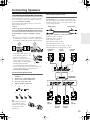
Available Speaker Placements According to
the Number of Speakers .............................21
Connection Examples....................................22
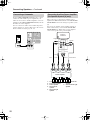
Connecting Speakers......................................25
Connecting to the Speaker Terminals ...........25
Connecting a Subwoofer ...............................26
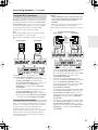
Connecting Auxiliary Power Amplifier
(For Speaker System [A] only)....................26
Using the BTL Connection.............................27
Using Bi-amp Connection..............................27
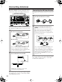
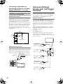
Connecting Antennas .....................................28
Connecting the Indoor FM Antenna...............28
Connecting the AM Loop Antenna.................28
Connecting an Outdoor FM Antenna.............29
Connecting an Outdoor AM Antenna.............29
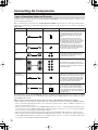
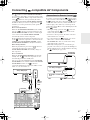
Connecting AV Components..........................30
Types of Connection Cables and
Terminals ....................................................30
Connecting Monitors such as TV or
Projector......................................................32
Connecting a DVD Player..............................33
Connecting a DVD Recorder or Digital VCR
(VIDEO 1)....................................................34
Connecting a VCR (VIDEO 2, VIDEO 3) .......35
Connecting a DBS Tuner, DBS TV, or
BS/CS Tuner...............................................37
Connecting a Portable DVD Player or
Video Camcorder ........................................38
Connecting a CD Player, Turntable or
Tuner...........................................................38
Connecting a Recording Device such as
MD Recorder, DAT Deck, CD Recorder or
Cassette Deck.............................................39
Connection Using the i.LINK (AUDIO)
Terminal ( )..............................................40
Connection Using HDMI Terminals............... 43
Connecting Components not Reached by the
Remote Controller Signals (IR IN/OUT)..... 45
If Remote Controller Signal Does not Reach the
TX-NR1000/TX-NR5000E Remote Sensor .... 45
If Remote Controller Signal Does not Reach
Other Components ..................................... 46
Using an External Device with 12V Trigger
Terminal....................................................... 46
Connecting -compatible AV
Components................................................ 47
Connections for Remote Control ( ) ......... 47
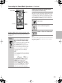
Basic Operation of Remote Controller
Buttons ........................................................ 48
To Operate the TX-NR1000/TX-NR5000E
(AMP Mode) ............................................... 48
To Select an Input Source ............................ 48
To Operate a Connected Component
(Mode Switching)........................................ 49
To Select a Source in Zone 2 or Zone 3....... 49
To Perform a Macro Operation ..................... 49
Customizing Your Remote Controller ........... 49
Connecting the Power/Basic Operations ..... 50
Turning on the Power.................................... 50
Operating on the TX-NR1000/TX-NR5000E
..... 50
Turning on the Power from the Remote
Controller.................................................... 51
Operating with Remote Controller................. 51
Using the Listening Modes............................ 56
Selecting the Listening Mode........................ 59
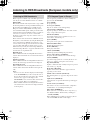
Listening to Radio Broadcasts...................... 60
Using the Tuner ............................................ 60
Tuning into a Radio Station........................... 60
Listening to RDS Broadcasts
(European models only)............................. 62
Listening to RDS Broadcasts........................ 62
PTY Program Types in Europe..................... 62
Displaying Radio Text (RT)........................... 63
Performing a PTY Scan ................................ 63
Performing a TP Scan................................... 63
Enjoying Multichannel Playback................... 64
How to Connect ............................................ 64
How to Set Up............................................... 64
Playing Back in Multichannel Sound............. 65
Adjusting the Volume Level of Speakers for
Multichannel Playback................................ 65
Enjoying Movies and Music in the Remote
Zone (Zone 2/3) ........................................... 66
Connecting and Setup .................................. 66
Enjoying Movies and Music in a Remote
Zone ........................................................... 67
Recording a Source........................................ 69
Recording Audio/Video While Playing .......... 70
Recording Audio/Video on a Component While
Playing Another .......................................... 70
Recording the Video from One Source and the
Audio from Another Source ........................ 71
Enjoying Net Audio......................................... 72
About Net-Tune............................................. 72
Networking Your TX-NR1000/TX-NR5000E
..... 73
Getting Started
Installation and Connections
Operations

5
Table of Contents
—Continued
About Network Configuration ........................73
Using the Remote Controller.........................74
Enjoying Internet Radio.................................76
Playing a Music File Saved on the Net-Tune
Server .........................................................78
Configuring the Music Server........................80
Setup Menu......................................................82
OSD Map (MAIN A)....................................... 82
OSD Map (MAIN B)....................................... 84
OSD Map (ZONE 2)......................................85
Navigating the Setup Menu...........................86
Hardware Setup...............................................87
Remote Control Setup Sub-menu.................87
TV Format Sub-menu.................................... 87
AM Frequency Setup Sub-menu
(Asian and Australian Models Only) ...........87
Speaker/Output Setup ....................................88
Speaker Configuration Sub-menu.................88
Speaker Impedance Sub-menu ....................89
Speaker Crossover Sub-menu......................89
Speaker Distance Sub-menu ........................89
Notch Filter Sub-menu ..................................90
Level Calibration Sub-menu..........................90
THX Audio Setup Sub-menu.........................91
Audio Output Assign Sub-menu....................91
Video Output Assign Sub-menu....................92
Input Setup ......................................................93
Audio Assign Sub-menu (when input is other
than NET AUDIO).......................................94
Music Server Sub-menu (When input is NET
AUDIO) .......................................................95
Video Assign Sub-menu................................ 95
Listening Mode Preset Sub-menu.................96
Character Edit Sub-menu.............................. 97
IntelliVolume Sub-menu................................98
Delay Sub-menu ...........................................98
12V Trigger Assign Sub-menu......................98
Listening Mode Setup.....................................99
Mono Setup Sub-menu .................................99
Multiplex Setup Sub-menu............................99
Stereo Setup Sub-menu.............................. 100
Direct, Pure Audio Setup Sub-menu...........101
Multichannel Input Setup Sub-menu...........102
i.LINK(IEEE1394):DVD-Audio Input Setup
Sub-menu .................................................103
i.LINK(IEEE1394):SACD Input Setup
Sub-menu .................................................105
Dolby Digital Setup Sub-menu....................106
DTS Setup Sub-menu.................................108
AAC Setup Sub-menu.................................109
Dolby Pro Logic IIx/DTS NEO:6 (2ch Input only)
Setup Sub-menu.......................................110
THX Setup Sub-menu.................................112
Mono Movie Setup/Enhance Setup/Orchestra
Setup/Unplugged Setup/Studio-Mix Setup/TV
Logic Setup Sub-menu .............................114
All Ch Stereo Setup/Full Mono Setup
Sub-menu .................................................115
Dolby Virtual Speaker Setup Sub-menu .....116
Dolby Headphone Setup Sub-menu ...........117
Audio Adjust..................................................118
Tone Control Sub-menu ..............................118
Preferences....................................................119
Volume Setup Sub-menu ............................119
Headphone Level Setup Sub-menu ............119
OSD Setup Sub-menu.................................119
OSD Position Sub-menu ............................119
i.LINK Setup...................................................120
Wakeup Setup.............................................120
OSD for DVD...............................................120
OSD for DVD (Zone 2) ................................120
DVD Output Synchro...................................120
Network Setup ...............................................121
IP Address Sub-menu ................................121
Proxy Sub-menu.........................................121
MAC
Address Sub-menu.............................121
Client Sub-menu..........................................122
Lock/Version Setup.......................................123
Lock Setup Sub-menu.................................123
Firmware Version Sub-menu.......................123
Operating Onkyo Products Using the Remote
Controller ...................................................124
Operating Onkyo Products Using the
Connection................................................124
DVD Mode...................................................124
CD Mode .....................................................126
MiniDisc Mode.............................................127
Tape Mode ..................................................128
Using the Remote Controller with Other
Components...............................................129
Entering a Remote Control Code ................129
Learning Commands from Another Remote
Controller ..................................................136
Using Macros...............................................137
Other Settings for the Remote Controller...139
Editing Remote Controller Modes................139
Resetting the Remote Controller .................141
Using the Remote Controller with Radio
Frequency (RC-558M only).......................141
Changing the Remote Controller’s
Control ID..................................................142
Relationship Between Input Source and
Listening Mode ..........................................143
Troubleshooting............................................146
Power ..........................................................146
Audio ...........................................................146
Video ...........................................................147
Tuner ...........................................................147
Remote Controller .......................................147
Recording ....................................................148
Zone 2/Zone 3 .............................................148
Net-Tune......................................................148
Others..........................................................148
Error Messages ...........................................149
Specifications................................................150
Setup Menu
Using the Remote Controller
Miscellaneous

6
Features
Amplifier Features
•
192 kHz/24-Bit DAC for All Channels
• Color-Coded Heavy Duty Dual Banana Plug
Compatible Transparent Speaker Posts
•
Color-Coded 7.1 Multi-Channel Inputs and Pre
Outs
• Powered Zone 2 and Zone 3
• 5 12V DC Trigger Outputs and 3 IR Inputs/
Outputs
•
Massive, Shielded Toroidal Transformer,
the kind
you find only in the best high end audio equipment, to
provide copious amounts of pure current
•
Huge Custom Designed Audio Tuned Reference
Capacitors
to deliver greater power at low
frequencies, and provide tremendous continuous
power reserves during the most dynamic sound
effects and music demands
•
Powerful Transistors.
These high power, high
quality transistors are ready to amplify your electrical
signals for the highest performance possible
•
High Grade Dual Aluminum Extruded Heatsinks
and auto-switched cooling fan to keep things cool
when the action gets hot
• WRAT (Wide Range Amplifier Technology)
• Optimum Gain Volume Circuitry
Audio/Video Features
• THX Ultra2 Certified
• THX Surround EX, DTS-ES Discrete/Matrix 6.1,
DTS NEO:6, DTS 96/24, Dolby Digital EX, Dolby
Pro Logic II/IIx, Dolby Headphone, Dolby Virtual
Surround
• 4 Wideband Component Video Inputs and 2
Outputs
•
Dual Monitor Outputs
(S Video/Composite) to
route the onscreen signal to a small monitor and make
adjustments without distracting the audience
•
13 Digital Inputs (1 Optical on Front)
(7 Optical/6
Coaxial/12 Assignable) to connect any variety of
digital sources to the TX-NR1000/TX-NR5000E’s
powerful digital processor
•
4 Digital Outputs
(2 Optical/2 Coaxial/4 Assignable)
to make direct digital dubs to other digital devices
•
Wolfson 192 kHz/24-Bit
D/A Converters for all
channels
•
Dual 32-Bit DSP Chips
for high grade main and
multizone decoding
• Non-Scaling Configuration
Next Generation User Interface
• HDMI (High Definition Multimedia Interface)
• i.Link (IEEE1394) Digital Input for DVD-Audio
and SACD
• Net-Tune Function with MP3/WAV/WMA
Decoding
• Ethernet Plug-In Capability and 1 Output
• Bi-Directional RS-232 Port to download new
programs and provide easy interface with
touchscreen controllers from other manufacturers
• Composite and S Video to Component Video
Upconversion (NTSC and PAL Compatible)
• Speaker A and B Mode for 7.1 Channels
• BTL and Bi-Wiring Connectable for FL/FR with
SBR/SBL
• Dual 32-Bit DSP Chips for high grade main and
multizone decoding
•
5 12V DC Trigger Outputs and 3 IR Inputs/
Outputs
for multizone operation of multiple
components
• Individual Crossover Adjustment
FM/AM Tuner Features
• 40 FM/AM Presets
• FM/AM Auto Tuning
Other Performance Features
• VLSC (Vector Linear Shaping Circuitry)
•
Solid Aluminum Volume Knob
for quality you can
feel—ergonomically pleasing and convenient for
those quick in-the-dark level changes
•
Separate PC Boards
to keep audio and video signals
completely separate
•
Rec Out Selector (On Front)
to tape one program
while watching or listening to another
•
Gold-Plated RCA Jacks
to resist corrosion and
provide distortion-free signal transmission
•
2 Sets of Color-Coded Heavy Duty, Transparent,
Dual-Banana-Plug Speaker Terminals
for all
channels to provide distortion-free signal transfer and
accommodate heavy gauge speaker cable
•
Impeccable Quality Materials
—a heavy gauge,
reinforced steel chassis, rigid aluminum panels and
brazen stabilizers to enhance overall chassis stability
•
Large Multi-Emitter Output Transistors
to provide
faster switching speed, which translates into a wider
dynamic range
•
Zone 2 Multiroom/Multisource
(audio and video) to
set up additional rooms
•
Detachable Heavy Duty IEC Power Cord
to
minimize interference from external sources and
increase power stability—detachable for ease of
installation

7
Features
—Continued
• Audiophile Grade Parts
• IntelliVolume
• Pure Audio Mode
• Digital Upsampling
• Absolute Ground Plate
• Large, Fluorescent, 35 Dot Matrix Display With 4
Mode Dimmer
• For Ultimate Control—The Last Remote You’ll
Ever Need
• A-Form Listening Mode Memory
In catalogs and on packaging, the letter added to the end
of the product name indicates the color of the
TX-NR1000/TX-NR5000E. Specifications and
operation are the same regardless of color.
• THX is a trademark or registered trademark of THX Ltd.
• HDMI, the HDMI logo and High Definition Multimedia
Interface are trademarks or registered trademarks of HDMI
Licensing, LLC.
• Manufactured under license from Dolby Laboratories.
“Dolby,” “Pro Logic,” “Surround EX,” and the double-D symbol
are trademarks of Dolby Laboratories.
• “DTS,” “DTS 96/24,” “DTS-ES,” and “NEO:6” are trademarks
of Digital Theater Systems, Inc.
• The i.LINK logo is a trademark of Sony Corporation, registered
in the U.S. and other countries.
• Re-Equalization and the “Re-EQ” logo are trademarks of THX Ltd.
• “Net-Tune” is a trademark of Onkyo Corporation.
• Windows Media and the Windows logo are trandemarks, or
registered trademarks of
Microsoft Corporation in the
United States and/or other
countries.
• Intel and Pentium are registered trademarks of Intel Corporation.
• MPEG Layer-3 audio coding technology licensed from
Fraunhofer IIS and THOMSON multimedia.
• Xantech is a registered trademark of Xantech Corporation.
• Niles is a registered trademark of Niles Audio Corporation.
“This product incorporates copyright protection technology that is
protected by U.S. patents and other intellectual property rights. Use
of this copyright protection technology must be authorized by
Macrovision Corporation, and is intended for home and other
limited consumer uses only unless otherwise authorized by
Macrovision. Reverse engineering or disassembly is prohibited.”
For European Models
THX Ultra2
Before any home theater component can be THX Ultra2 certified, it
must pass a rigorous series of quality and performance tests. Only
then can a product feature the THX Ultra2 logo, which is your
guarantee that the Home Theater products you purchase will give
you superb performance for many years to come. THX Ultra2
requirements define hundreds of parameters, including power
amplifier performance, and pre-amplifier performance and
operation for both digital and analog domains. THX Ultra2
receivers also feature proprietary THX technologies (e.g., THX
Mode) which accurately translate film soundtracks for home theater
playback.
Declaration of Conformity
We,
ONKYO EUROPE
ELECTRONICS GmbH
LIEGNITZERSTRASSE 6,
82194 GROEBENZELL,
GERMANY
GROEBENZELL, GERMANY
ONKYO EUROPE ELECTRONICS GmbH
I. MORI
declare in own responsibility, that the ONKYO product
described in this instruction manual is in compliance with the
corresponding technical standards such as EN60065,
EN55013, EN55020 and EN61000-3-2, -3-3.

8
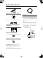
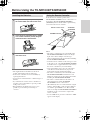
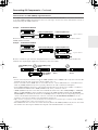
Supplied Accessories
Make sure you have the following accessories:
Plug the supplied power cord into this AC INLET.
• Do not use a power cord other than the one supplied
with the TX-NR1000/TX-NR5000E. The power cord
supplied is designed for use with the TX-NR1000/
TX-NR5000E and should not be used with any other
device.
• Never have the power cord disconnected from the
TX-NR1000/TX-NR5000E while the other end is
plugged into the wall outlet. Doing so may cause an
electric shock. Always connect by plugging into the
wall outlet last and disconnect by unplugging from
the wall outlet first.
Remote Controller & Three Batteries (AA/R6)
AM Loop Antenna (not supplied with USA and Cana-
dian models)
Indoor FM antenna (not supplied with USA and
Canadian models)
(connector type varies from country to country)
Speaker Labels
Terminal Wrench
A wrench to screw/unscrew the speaker terminal cap.
Power Plug adapter
Only supplied in certain countries. Use this adapter if
your AC outlet does not match the plug on the
TX-NR1000/TX-NR5000E’s power cord (adapter varies
from country to country).
Front
Left
Front
Left
SP-B
/
Zone 2
Left
SP-B
/
Zone 2
Left
Surround
Right
Surround
Right
Surround Back
Right
Surround Back
Right
Zone 2
Right
Zone 2
Right
Front
Left
Front
Left
SP-B
/
Zone 2
Left
SP-B
/
Zone 2
Left
Front
Right
Front
Right
SP-B
/
Zone 2
Right
SP-B
/
Zone 2
Right
Front
Right
Front
Right
SP-B
/
Zone 2
Right
SP-B
/
Zone 2
Right
Surround
Right
Surround
Right
Center
Center
Center
Center
Surround
Left
Surround
Left
Surround
Left
Surround
Left
Surround Back
Right
Surround Back
Right
Zone 2
Right
Zone 2
Right
Surround Back
Left
Surround Back
Left
Zone 2
Left
Zone 2
Left
Surround Back
Left
Surround Back
Left
Zone 2
Left
Zone 2
Left
1
2
3
Speaker Cable
Power Cord
Connecting the Supplied Power Cord
AC
INLET
DO NOT connect the
power cord at this time.
Power Cord
(supplied)

9
Before Using the TX-NR1000/TX-NR5000E
Notes:
• The supplied batteries should last for about six
months, although this will vary with usage.
• If the remote controller doesn’t work reliably, try
replacing the batteries.
• Don’t mix new and old batteries, or different types of
batteries.
• If you intend not to use the remote controller for a
long time, remove the batteries to prevent possible
leakage and corrosion.
• Expired batteries should be removed as soon as
possible to prevent damage from leakage or
corrosion.
To use the remote controller, point it at the
TX-NR1000/TX-NR5000E’s remote control sensor, as
shown below. The TX-NR1000/TX-NR5000E’s
[STANDBY] indicator flashes while a signal is being
received from the remote controller.
Notes:
• The remote controller may not work reliably if the
TX-NR1000/TX-NR5000E is subjected to bright
light, such as direct sunlight or inverter-type
fluorescent lights. Keep this in mind when installing
the TX-NR1000/TX-NR5000E.
• If another remote controller of the same type is used
in the same room, or the TX-NR1000/TX-NR5000E
is installed close to equipment that uses infrared rays,
the remote controller may not work reliably.
• Don’t put anything, such as a book, on the remote
controller, because the buttons may be pressed
inadvertently, thereby draining the batteries.
• The remote controller may not work reliably if the
TX-NR1000/TX-NR5000E is installed in a rack
behind colored glass doors. Keep this in mind when
installing the TX-NR1000/TX-NR5000E.
• The remote controller will not work if there’s an
obstacle between it and the TX-NR1000/
TX-NR5000E’s remote control sensor.
• (RC-558M only) You can set the transmission signal
format to infrared (IR), or radio frequency (RF) for
use with the optional RF Receiver. This is useful
when, for example, the TX-NR1000/TX-NR5000E is
installed in a rack or is not in line of sight of the
remote controller.
• To select AMP mode, press the scroll wheel. “AMP”
appears on the display.
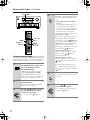
Installing the Batteries
1
To open the battery compartment, press
the small hollow and slide off the cover.
2
Insert the three supplied batteries (AA/R6)
in accordance with the polarity diagram
inside the battery compartment.
3
Put the cover onto the remote controller
and slide it shut.
Using the Remote Controller
30˚
30˚
Approx. 16 ft. (5 m)
Remote control sensor
STANDBY indicator
TX-NR1000/
TX-NR5000E

10
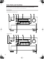
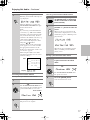
Index Parts and Facilities
Here is an explanation of the controls and displays on the front panel of the TX-NR1000/TX-NR5000E.
The specifications for your model may differ due to regional requirements.
Front Panels
STANDBY/ON
STANDBY
PURE AUDIO
MASTER VOLUME
OPEN
ZONE 2
()
GREEN
MAIN
()
BLUE
REC
/
ZONE 3
(
)
RED
DISPLAY CD NET AUDIOPHONOTUNERTAPE 1 TAPE 2
DVD
VIDEO
3
VIDEO 4 VIDEO 5 VIDEO 6 VIDEO 7VIDEO 2VIDEO 1
OFF
ON
STANDBY/ON
STANDBY
PURE AUDIO
MASTER VOLUME
POWER
OPEN
ZONE 2
()
GREEN
MAIN
()
BLUE
REC
/
ZONE 3
(
)
RED
DISPLAY CD NET AUDIOPHONOTUNERTAPE 1 TAPE 2
DVD
VIDEO
3
VIDEO 4 VIDEO 5 VIDEO 6 VIDEO 7VIDEO 2VIDEO 1
USA, Canadian, and Australian models
European models

11
Index Parts and Facilities
—Continued
For further operational instructions, see the pages
indicated in brackets [ ].
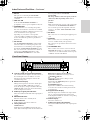
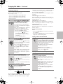
1
POWER switch (for all models other than
USA, Canadian, and Australian models) [50]
Press to turn on and off the main power supply for
the TX-NR1000/TX-NR5000E. When the
TX-NR1000/TX-NR5000E is turned on with the
[POWER] switch, the [STANDBY] indicator lights.
• Before turning on the power, check to make sure
that all cords are properly connected.
• When the power is turned on, a sudden surge of
current will occur that may adversely affect the
operation of other devices. To prevent this, do not
plug the TX-NR1000/TX-NR5000E into the same
circuit used by sensitive equipment, e.g., computers.
2
STANDBY indicator [9, 50]
Lights when the TX-NR1000/TX-NR5000E is in
the standby state and when a signal is received from
the remote controller.
3
STANDBY/ON button [50]
If pressed with the [POWER] switch turned on (with
the receiver plugged in for USA, Canadian, and
Australian models), the TX-NR1000/TX-NR5000E
turns on and the display lights up. If pressed again, the
TX-NR1000/TX-NR5000E returns to the standby
state. In the standby state, the display is turned off and
the TX-NR1000/TX-NR5000E cannot be operated.
4
Remote control sensor [9]
5
DISPLAY button [54]
Press to display information about the current input
source signal. Each time you press the [DISPLAY]
button, the screen changes to show you different
information concerning the input signal.
6
Front display
7
Input source buttons and indicators (DVD,
VIDEO 1–7, TAPE 1-2, TUNER, PHONO, CD,
and NET AUDIO) [50, 60, 63, 76]
Press these buttons to select the input source for the
main zone.
After selecting the input source, the corresponding
indicator turns blue. If you select Zone 2, the
indicator turns green. If you select Zone 3 or Rec,
the indicator turns red.
8
MASTER VOLUME dial [50]
Use to control the volume in the main zone. The
volume for the remote zone (Zone 2 and Zone 3) is
independent.
9
OPEN button
Press this button to open the front panel door.
0
PURE AUDIO indicator [59]
Lights during pure audio playback.

12
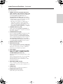
Index Parts and Facilities
—Continued
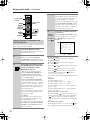
Inner Panels
TUNING
MODE
MEMORY
SETUP
EXIT
PHONES
VIDEO 7 INPUT
S VIDEO
DIGITAL
AUDIO
VIDEO L R
LISTENING
MODE
AUDIO
SELECTOR
TONE
CLEAR
DIMMER
ZONE
2 REC/
ZONE 3
LEVEL LEVEL
SELECT/
PRESET
CONTROL
/
TUNING
PUSH TO ENTER
PUSH TO ENTER
TUNING
MODE
MEMORY
SETUP
EXIT
PHONES
VIDEO 7 INPUT
S VIDEO
DIGITAL
AUDIO
VIDEO L R
LISTENING
MODE
AUDIO
SELECTOR
TONE
CLEAR
RT/
PTY/
TP
ZONE
2 REC/
ZONE 3
LEVEL LEVEL
SELECT/
PRESET
CONTROL
/
TUNING
PUSH TO ENTER
PUSH TO ENTER
USA, Canadian, and Australian models
European models

13
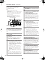
Index Parts and Facilities
—Continued
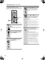
A
LISTENING MODE button [59]
Press this button to enter the setup mode for the
listening mode. Turning the [SELECT/PRESET]
allows you to select the listening mode. To confirm
your selection and exit the setup mode, press the
[SELECT/PRESET].
B
AUDIO SELECTOR button [55]
Press this button to enter the audio selector mode.
Turning the [SELECT/PRESET] allows you to
select the audio mode.
C
TONE button [52]
Press this button to enter the tone adjustment mode.
Turning the [SELECT/PRESET] allows you to
select the channel to adjust the tone. To adjust the
tone level, turn the [CONTROL/TUNING].
D
ZONE 2 button [68]
Press this button to enter the Zone 2 configuration
mode. Turning the [SELECT/PRESET] allows you
to select the input source for Zone 2. Also, if you
want to configure other Zone 2 settings such as
standby/on setting, listening mode, volume
adjustment, audio selector mode, and display
settings, press this button first.
E
REC/ZONE 3 button [68, 70]
Press this button to enter the Rec/Zone 3 mode.
Turning the [CONTROL/TUNING] allows you to
select the input source for the Rec mode or Zone 3.
Also, if you want to configure the setting for Zone 3
including standby/on setting or volume adjustment,
press this button first.
Note:
Recording and Zone 3 operations uses the same
circuit and therefore cannot be used at the same
time.
F
VIDEO 7 INPUT terminals
For connecting a video camera or game device.
G
ZONE 3 LEVEL button [68]
Press this button to enter the volume adjustment
mode for Zone 3. Turning the [SELECT/PRESET]
allows you to adjust the volume.
H
CONTROL/TUNING dial [52, 60, 68, 70, 86]
When the input source is FM or AM, turning this jog
dial allows you to select the frequency to receive.
When used with other buttons, this [CONTROL/
TUNING] dial is used to select the mode settings or
values. Also the dial is pressed to confirm the
settings or values you select.
I
SETUP button [86]
Press this button to enter the setup mode. First,
select the parameter to change by turning the
[SELECT/PRESET] and press the [SELECT/
PRESET] to confirm the parameter. Then, change
the parameter value by turning the [CONTROL/
TUNING] and press the [CONTROL/TUNING] to
confirm the value.
J
EXIT button [86]
Press this button to return to the last menu. To exit
from the setup mode, press the [SETUP] button again.
K
SELECT/PRESET dial [59, 61, 63, 68, 71, 86]
When the input source is FM or AM, turning this
jog dial allows you to switch between your preset
stations. When used with other buttons, the
[SELECT/PRESET] dial is used to select the mode
settings or parameters. Also the dial is pressed to
confirm the settings or parameters you select.
L
ZONE 2 LEVEL button [68]
Pressing this button enters the volume adjustment
mode for Zone 2. To adjust volume, turn the
[SELECT/PRESET].
M
DIMMER button (Other than European
models) [52]
Press to set the brightness of the front display. There are
four settings available: normal, dark, very dark, and
volume only.
For European models, this function can be operated
only with the remote controller.
M
RT/PTY/TP button (European models only) [63]
This button is only available on European models.
Press this button to tune into the Radio Data System
(RDS) for FM broadcasting. RDS was developed
within the European Broadcasting Union (EBU)
and is available in most European countries. Each
time the button is pressed, the display changes from
RT (radio text) to PTY (program type) to TP (traffic
program) and then back to RT again.
N
MEMORY button [61]
Press to assign the radio station, to which you are
currently tuned, as a preset channel or press to
delete a previously preset station.
O
TUNING MODE button [60, 61]
This button is used to select the Auto or Manual
Tuning Mode.
P
PHONES jack [52]
This is a standard stereo jack for connecting stereo
headphones.

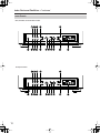
14
Index Parts and Facilities
—Continued
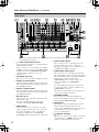
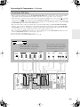
1
( ) i.LINK S400 (AUDIO) terminals
Some of the Asian models are not equipped with the
i.LINK(AUDIO) terminals.
These connectors are for connecting to the i.LINK
(AUDIO)-ready device using a 4-pin (S400) i.LINK
(AUDIO) cable. The TX-NR1000/TX-NR5000E
complies with the standards on audio only
transimissions.
2
ETHERNET (Net-Tune)
This connector is for connecting to an Ethernet network.
3
DIGITAL OPTICAL IN/OUT
The input/output terminals for digital sound signal.
The sound quality equals the signal passed through
the COAXIAL terminals.
4
DIGITAL COAXIAL IN/OUT
The input/output terminals for digital sound signal.
The sound quality equals the signal passed through
the OPTICAL terminals.
5
MULTI-CH IN 1/2
This connector is for connecting components with a
multichannel output.
Two sets of multichannel input terminals are
available on the TX-NR1000/TX-NR5000E.
6
AUDIO IN/OUT
These connectors are for connecting to the audio
input and output jacks on audio/video components.
To connect a turntable, connect to the PH jacks.
In addition to the PH jacks, the TX-NR1000/
TX-NR5000E offers nine input and five output jacks.
7
VIDEO/S VIDEO IN/OUT
These connectors are for connecting to the video
input and output jacks on video components.
Six input and 4 output jacks are available for each
of VIDEO and S VIDEO connection.
8
COMPONENT VIDEO IN/OUT
These connectors are for connecting to the component
video outputs/inputs of video components that have them.
European and Asian models are equipped with three
inputs and one output for the RCA-type
COMPONENT connection and one input and
output for the BNC-type COMPONENT
connection.
For other than European and Asian models, there
are four inputs and two outputs for the RCA-type
COMPONENT connection.
Check the type of terminals or jacks on the device to
connect before making connections.
9
ANTENNA (FM/AM)
These jacks are for connecting the FM indoor
antenna and the AM loop antenna that are supplied
with the TX-NR1000/TX-NR5000E.
0
HDMI IN/OUT
This interface can transfer digital audio and video
signals simultaneously. The terminal can be
connected to the HDMI terminal on the components
such as DVD player, set top box (B tuner),
projector, and digital TV.
A
REMOTE CONTROL
This jack is for connecting other Onkyo components
equipped with the same terminal. The audio
connection cables must also be connected.
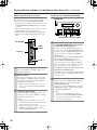
Rear Panel
E
GND
“Net
-
Tune”
is
a
trademark
of
Onkyo
Corporation.
ETHERNET
(
Net
-
Tune
)
A
REMOTE
CONTROL
MAIN
ZONE
3
ZONE
2
IN
AC
INLET
A
L
R
FRONT SURR SURR
BACK
CENTER
SUB
WOOFER
SUB
WOOFER
FRONT
L
CENTERFRONT
R
SURR BACK
L
(
ASSIGNABLE
)
SURR
R
SURR
L
FRONT
R
(
BTL
)
FRONT
L
(
BTL
)
IR
12V
TRIGGER
OUT
RS
232
PRE
OUT
A
(
SINGLE
)
PRE
OUT B
C
E
200mA MAX.
100mA MAX.
100mA MAX.
100mA MAX.
100mA MAX.
AC 120V 60Hz
SWITCHED
120W 1A MAX.
AC
OUTLET
UDC/UDT
SPEAKERS A
SPEAKERS B
22
1
66
55
44
33
22
11
OPTICAL COAXIAL
AUDIO IN
1
3
2
1
PH
2
3
9
8
7
6
5
4
4
5
RL
LR
LR
R L
G
IN
1
IN
2
HDMI
S
VIDEO VIDEO
IN IN
IN
1
IN
2
3
2
1
Y
P
B
P
R
COMPONENT
VIDEO
IN
3
6
5
4
Y
P
B
P
R
2
1
4
3
Y
P
B
P
R
Y
P
B
P
R
COMPONENT VIDEO
IN
4
ANTENNA
FM
75
B
SURR BACK
R
(
ASSIGNABLE
)
A
B
D
DIGITAL IN DIGITAL IN
LR
S VIDEOS VIDEO VIDEOVIDEO
OUT
MODEL NO.
TX
-
NR
1000
CD
OUT
OUT
F
L
OUT
IH
OUT OUT
J
K
OUT
1
OUT
2
AM
1
SBR SBL
SR SL
SUB C
FR FL
SBR SBL
SR SL
SUB C
FR
FL
MULTI
-
CH
IN
1
MULTI
-
CH
IN
2
B
*
*This terminal is provided for future service enhancement and is not used currently. Never plug the cable connector for
other terminals into this terminal.

15
Index Parts and Facilities
—Continued
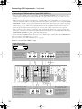
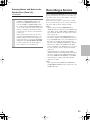
B
RS 232
This port is for connecting the TX-NR1000/
TX-NR5000E to home automation and external
controllers.
C
PRE OUT A/B
To use the TX-NR1000/TX-NR5000E as a
preamplifier, connect a power amplifier to this jack.
D
SPEAKERS A/B
These terminals are for connecting the speakers.
Two sets of home theater connections are available
(simultaneous playback of different sources in each
of two home theaters is not supported).
Depending on your system, various speaker
connections will be available. For example, you can
use the surround back speakers for playback in a
different room.
E
AC OUTLET
The TX-NR1000/TX-NR5000E is equipped with
AC mains outlets for connecting the power cords
from other devices so that their power is supplied
through the TX-NR1000/TX-NR5000E. By doing
this, you can leave the connected device turned on
and have the [STANDBY/ON] button on the
TX-NR1000/TX-NR5000E turn on and off the
device together with the TX-NR1000/
TX-NR5000E.
The shape, number, and total capacity of the AC
outlets may differ depending on the area of
purchase.
Caution:
Make sure that the total capacity of the components
connected to the TX-NR1000/TX-NR5000E does
not exceed the capacity that is printed on the rear
panel (e.g., AC 120V - 60Hz SWITCHED 120W
1A MAX.).
F
AC INLET
This connector is for connecting the supplied power
cord.
G
IR IN/OUT
These connectors are for connecting the remote
sensor of a multiroom kit (sold separately).
The connectors are provided for main room, Zone 2,
and Zone 3.
H
12V TRIGGER OUT
These connectors are used to connect to the 12V
TRIGGER IN terminal of a component. Available
connectors are one with maximum current capacity
of 200 mA and four with 100 mA.
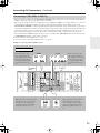
A
Listening mode or input format indicators
One of these indicators lights to show the format of
the current input source. In addition, one of the
listening mode indicators lights to indicate the
current listening mode.
B
Multifunction display
During normal operation, shows the current input
source. When the FM or AM input is selected,
shows the frequency and preset number. When the
[DISPLAY] button is pressed, shows the listening
mode and input source format.
C
Audio input signal path indicators
Shows from which terminal the audio input signal is
coming.
D
MAIN A/B indicators
Indicates which room is currently in use.
E
SLEEP indicator
Lights when the sleep timer is turned on.
F
Tuning indicators
AUTO indicator
Lights when receiving FM broadcasts in the stereo
mode. Turns off when placed into the monaural mode.
RDS indicator (European models only)
Lights when an RDS station is being received.
TUNED
indicator
Lights when a radio station is being received.
MEMORY indicator
Lights when the [MEMORY] button is pressed to
preset a radio station.
FM STEREO indicator
Lights when an FM broadcast station is being
received in stereo. Turns off when placed into the
monaural mode.
G
Program format display
When the input source is DVD video, Super Audio
CD, or compressed digital audio signal such as
Dolby Digital and DTS, the channels corresponding
to the input source light.
H
Volume display
Shows the volume level.
I
Video input signal path indicators
Shows from which terminal the video input signal is
coming.
Front Panel Display

16
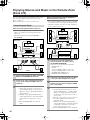
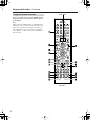
Index Parts and Facilities
—Continued
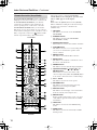
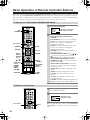
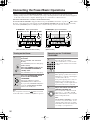
The TX-NR1000/TX-NR5000E’s remote controller is a
multipurpose device that can be used to control not just
the TX-NR1000/TX-NR5000E but your other AV
components as well. This section explains how its
various operating modes can be used to control the
TX-NR1000/TX-NR5000E. When you use the Net-
Tune mode, see page 74 for details. See page 124-136
for information on using the remote controller to control
Onkyo components connected via and TVs, VCRs,
and AV components made by other manufacturers.
Amp mode is used to control the TX-NR1000/
TX-NR5000E.
To select Amp mode, press the scroll
wheel. “AMP” appears on the display.
Note:
While neither the [INPUT] button nor the [MODE]
button is illuminated, rolling the scroll wheel changes
the input source and remote controller mode
simultaneously.
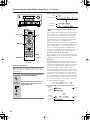
1
ON button
This button is used to turn on the TX-NR1000/
TX-NR5000E.
2
STANDBY button
This button is used to set the TX-NR1000/
TX-NR5000E to Standby.
3
Number/letter buttons
These buttons are used to enter numbers and letters.
4
CUSTOM button
This button is used to access various settings that
you can use to customize the operation of the
remote controller.
5
MACRO button
This button is used with the Macro function.
6
MODE button
This button is used with the scroll wheel to select
the remote controller modes.
7
DIMMER button
This button is used to adjust the display brightness.
8
Up/Down/Left/Right [ ]/[ ]/[ ]/[ ] &
ENTER buttons
These buttons are used to select items on the
onscreen setup menus (OSD). The [ENTER] button
is also used to enter names and to confirm settings.
9
CH +/– button
This button is used to select radio presets.
0
RETURN button
This button is used to return to the previously
displayed onscreen setup menu (OSD).
A
DISPLAY button
This button is used to display various information
about the currently selected input source.
B
MAIN A button
For the speakers used in main room A, every press
of this button toggles the status between enabled
and disabled.
C
THX button
This button is used to select the THX listening
modes.
D
SURR button
This button is used to select the Dolby and DTS
listening modes.
Remote Controller (Amp Mode)
--
/
---
@.
-
'
/ ABC DEF
PQRS TUV WXYZ
DIRECT TUNING
GHI JKL MNO
CAPS DELETE
LANGUAGE LOCATION
ALBUM AR
TIST GENRE
PLAYLIST
REPEAT VIDEO MUSIC PHOTO
CUSTOM
DISPLAY
DIMMER
T
V
INPUT
SLEEP
RANDOMREC
MAIN A MAIN B
MUTING
ENTER
LAST MANGLE
SUBTITLE
AUDIO
MEMORY
SEARCHA
-
BREPEAT
ON STANDBY
TV
TV CH
TV VOL
S
E
R
V
E
R
A
U
D
I
O
A
D
J
E
X
I
T
G
U
I
D
E
PREV
CH
+
10 0
CLEAR
123
456
789
INPUT
T
O
P
M
E
N
U
M
E
N
U
S
E
T
U
P
R
E
T
U
R
N
ZONE
2
INPUTMODE
MACRO
VOL
CH
DISC
TEST T
O
NE
CH SEL
PURE A
SURR
DIRECT
STEREO
Re
-
EQ
THX
A
LL
ST
LEVEL
+
LEVEL
-
L NIGHT
AUDIO
SEL
DSP DSP
+
-
+
-
I
ZONE
3
#
Scroll wheel
RC-557M
RC-558M

17
Index Parts and Facilities
—Continued
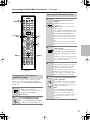
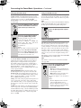
E
DIRECT button
This button is used to select the Direct listening
mode.
F
PURE A button
This button is used to select the Pure Audio listen-
ing mode.
G
TEST TONE, CH SEL, LEVEL– & LEVEL+
buttons
These buttons are used to adjust the level of each
speaker individually. These functions can be set
only with the remote controller. The [LEVEL–] and
[LEVEL+] buttons are also used to adjust the
volume in Zone 2 or Zone 3.
H
AUDIO SEL button
This button is used to select the audio input signal
format: analog, digital, multichannel, or i.LINK.
I
LIGHT button
This button is used to turn on or off the remote con-
troller’s illuminated buttons.
J
DIRECT TUNING button
This button is used with the number buttons to
select a radio station by entering its frequency. Press
this button first, and then use the number buttons to
enter the frequency.
K
Display
The top line of this LCD display shows the name of
the currently selected input source. The bottom line
shows the currently selected remote controller
mode.
L
ZONE 3 button
This button is used when you want to set the volume
and input source for Zone 3.
M
ZONE 2 button
This button is used when you want to set the volume
and input source for Zone 2.
N
INPUT button
This button is used to select the input source. Press
this button first, and then roll the scroll wheel until
the name of the input source appears on the display.
O
SLEEP button
This button is used to set the Sleep function. This
function can be set only with the remote controller.
P
VOL button
This button is used to set the volume of the
TX-NR1000/TX-NR5000E.
Q
SETUP button
This button is used to access the onscreen setup
menus (OSD) that appear on the TV.
R
MUTING button
This button is used to mute the TX-NR1000/
TX-NR5000E. This function can be set only with
the remote controller.
S
MAIN B button
For the speakers used in main room B, every press
of this button toggles the status between enabled
and disabled.
T
All ST button
This button is used to select the All Ch Stereo
listening mode.
U
STEREO button
This button is used to select the Stereo listening
mode.
V
DSP/DSP buttons
These buttons are used to select the listening modes.
W
Re-EQ button
This button is used to turn on and off the Re-EQ
function.
X
L NIGHT button
This button is used to set the Late Night function.

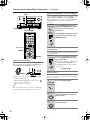
18
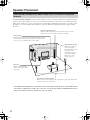
Speaker Placement
The TX-NR1000/TX-NR5000E has many excellent features to recreate a clear three-dimensional sound image and lively
sound movement. This enables you to enjoy, at home, the rich sound effects of a live theater or concert hall performance.
When playing a DVD, you can enjoy sound effects provided by DTS or Dolby Digital, depending on recording format.
In addition, you can enjoy THX sound and Onkyo’s proprietary DSP surround playback for TV or digital satellite
broadcasts.
• For optimum surround playback, set the distance between the listener and the speakers so that the time it takes
the sound to reach the listener is same. Also, you need to set each speaker volume level individually in order to
balance the volume level between speakers (See pages 88 and 90).
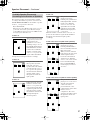
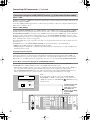
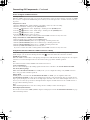
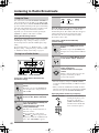
Basic Speaker Placements for Home Theater and the Function of Respective
Speakers
Center speaker
Complements the sound effects from front left and right speakers
to enrich and clear the sound image and movement. In movies, an
actor’s speech comes mainly from the center speaker.
Subwoofer
Outputs only bass sounds to
enhance and complement bass
sound effects.
Front left and right speakers
Outputs overall sound. They play the most important role in a home
theater system, by creating basic sound images and fields.
Surround left and right speakers
Enhances the sensation of being at a live performance by giving three-dimensional
sound movement to the sound effects.
Surround back speakers
Enhances the sound space
representation with
surround channel signals.
Recreating sound
movement effects and
sound fields behind the
listener gives a more
realistic experience.

19
Speaker Placement
—Continued
To fully enjoy surround sound, the configuration and placement of the speakers used are important. Be sure to read
through the descriptions in the previous page and shown below.
This section provides the examples and descriptions that assume a typical situation.
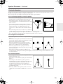
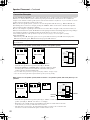
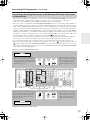
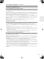
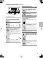
Front Left and Right Speakers, and Center Speaker
• Place the front left and right speakers symmetrically and so
that the distance from the listening position is the same.
• When placing speakers, direct the speakers toward the
position of the listener’s ears where the listener sits to enjoy
music or movies.
• Place the three speakers so that the heights of the three
speakers are aligned. The ideal height for the speakers is the
height of the listener’s ears. When placing the center
speaker above or below the TV, tilt it toward the listener’s
ears.
• Place the center speaker as close to the screen or monitor as
possible and in the center between the left and right front
speakers. When placing the center speaker near the TV, use a shielded speaker.
• If no center speaker is used, place the left and right front speakers closer to each other.
Left and Right Surround Speakers
• Place these speakers on each side of, or angled behind, the
listener.
• Place the surround speakers symmetrically from the listener
position and so that the distance from the listener is equal
between left and right surround speakers.
• When enjoying mainly movies, placing the surround
speakers about 3 feet (1 m) higher than the height of the
listener’s ears, results in more of a surround effect.
• When enjoying mainly music, placing the surround
speakers at the height of the front speakers may provide a
better surround effect.
• When using surround back speakers in addition to the
surround speakers, placing the surround speakers slightly forward from their current position will make the sound
movement smoother.
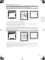
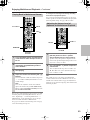
Surround Back Speakers
• Place the speakers about 3 feet (1 m) or higher than the
height of the listener’s ears.
• When using one surround back speaker, place it behind the
listener.
• When using two surround back speakers, place them
behind the listener so that the angles between the lines from
each surround back speaker to the listener and a line
straight back from the listener are about 30 degrees,
forming an equilateral triangle of the listener and the two
surround back speakers.
*When using a THX-certified speaker system, also refer to
“Speaker Placement Suitable for THX Audio” on the next
page.
Placing the Speakers
Front
Left
Left
Front
Front
Right
Right
Front
Left
Front
Right
Center
TV or screen
TV
Surround Back

20
Speaker Placement
—Continued
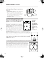
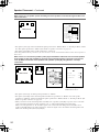
Subwoofer
Using a subwoofer greatly improves the volume level and
sound quality of bass sounds. The subwoofer effect depends
not only on the listening position but also on the shape of the
listening room.
• In general, place the subwoofer in a corner of the room or at
a point 1/3 the width of the room.
• Play a movie or music that contains high quality bass
sounds to determine the subwoofer placement. Change the
subwoofer’s position and check the effect, then select the
position where the bass sounds are best heard.
• You can place two subwoofers for more powerful and
richer heavy bass sounds.
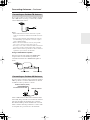
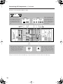
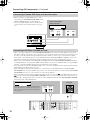
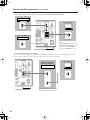
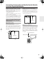
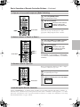
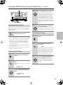
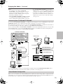
To enjoy sources using the THX Cinema or THX Surround EX
technology, we recommend using a THX speaker system from
THX Ltd. A speaker system supporting the THX Ultra2
standard is best suited for THX Ultra2 Cinema or THX Music
Mode.
The layout example on the right represents a case using the
dipole speakers. A dipole speaker is a two-way directivity
speaker that outputs the same sound in two directions such as
forward and backward.
Most dipole speakers are marked with an arrow indicating how
they should be oriented in the room in order to match their
phases*. Dipole surround speakers should be placed so that
their arrows point forward toward the screen, and dipole
surround back speakers should be placed so that their arrows
point toward each other.
*Phase: The word represents the waveform position in one cycle (0 to 360 degrees) of a sine wave. If
the phase does not match between multiple waveforms due to the distance between multiple speakers,
the speaker orientation, or the miswiring of positive and negative poles, the sound image or space may
be obscured or the sound may be less easy to listened to.
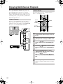
When playing the source in the THX Ultra2 Cinema or THX Music Mode format using two
surround back speakers supporting the THX Ultra2 standard, place them as close together as
possible. After placing the surround back speakers, perform the settings described in the
“THX Audio Setup” (page 91).
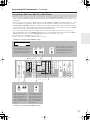
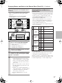
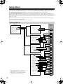
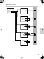
This placement is based on the ITU-R* recommendation. In this placement, five
speakers with the same performance capabilities are used for front left and right,
center, and left and right surround speakers, and they are placed so that the distances
between every speaker and the listening position are equal to each other and the
heights of the speaker and the listener’s ears are in the same. A mixing studio used
for making multichannel DVD-Audio source material adopts this placement.
*ITU-R: International Telecommunication Union Radiocommunication Sector
1/3 room
length
Corner
Speaker Placement Suitable for THX Audio
Speaker Placement Suitable for a Music Source such as DVD-Audio
Layout with dipole speakers
3
2
4
5
1
67
8 9
10
1 TV or screen
2 Subwoofer
3 Front left speaker
4 Center speaker
5 Front right speaker
6 Surround left speaker
7 Surround right
speaker
8 Surround back left
speaker
9 Surround back right
speaker
10 Listening position
6
7
10
89
As close as
possible
60
Center
SR
SL
Sub-
woofer
Front
Right
Front
Left
Page is loading ...
Page is loading ...
Page is loading ...
Page is loading ...
Page is loading ...
Page is loading ...
Page is loading ...
Page is loading ...
Page is loading ...
Page is loading ...
Page is loading ...
Page is loading ...
Page is loading ...
Page is loading ...
Page is loading ...
Page is loading ...
Page is loading ...
Page is loading ...
Page is loading ...
Page is loading ...
Page is loading ...
Page is loading ...
Page is loading ...
Page is loading ...
Page is loading ...
Page is loading ...
Page is loading ...
Page is loading ...
Page is loading ...
Page is loading ...
Page is loading ...
Page is loading ...
Page is loading ...
Page is loading ...
Page is loading ...
Page is loading ...
Page is loading ...
Page is loading ...
Page is loading ...
Page is loading ...
Page is loading ...
Page is loading ...
Page is loading ...
Page is loading ...
Page is loading ...
Page is loading ...
Page is loading ...
Page is loading ...
Page is loading ...
Page is loading ...
Page is loading ...
Page is loading ...
Page is loading ...
Page is loading ...
Page is loading ...
Page is loading ...
Page is loading ...
Page is loading ...
Page is loading ...
Page is loading ...
Page is loading ...
Page is loading ...
Page is loading ...
Page is loading ...
Page is loading ...
Page is loading ...
Page is loading ...
Page is loading ...
Page is loading ...
Page is loading ...
Page is loading ...
Page is loading ...
Page is loading ...
Page is loading ...
Page is loading ...
Page is loading ...
Page is loading ...
Page is loading ...
Page is loading ...
Page is loading ...
Page is loading ...
Page is loading ...
Page is loading ...
Page is loading ...
Page is loading ...
Page is loading ...
Page is loading ...
Page is loading ...
Page is loading ...
Page is loading ...
Page is loading ...
Page is loading ...
Page is loading ...
Page is loading ...
Page is loading ...
Page is loading ...
Page is loading ...
Page is loading ...
Page is loading ...
Page is loading ...
Page is loading ...
Page is loading ...
Page is loading ...
Page is loading ...
Page is loading ...
Page is loading ...
Page is loading ...
Page is loading ...
Page is loading ...
Page is loading ...
Page is loading ...
Page is loading ...
Page is loading ...
Page is loading ...
Page is loading ...
Page is loading ...
Page is loading ...
Page is loading ...
Page is loading ...
Page is loading ...
Page is loading ...
Page is loading ...
Page is loading ...
Page is loading ...
Page is loading ...
Page is loading ...
Page is loading ...
Page is loading ...
Page is loading ...
Page is loading ...
Page is loading ...
Page is loading ...
-
 1
1
-
 2
2
-
 3
3
-
 4
4
-
 5
5
-
 6
6
-
 7
7
-
 8
8
-
 9
9
-
 10
10
-
 11
11
-
 12
12
-
 13
13
-
 14
14
-
 15
15
-
 16
16
-
 17
17
-
 18
18
-
 19
19
-
 20
20
-
 21
21
-
 22
22
-
 23
23
-
 24
24
-
 25
25
-
 26
26
-
 27
27
-
 28
28
-
 29
29
-
 30
30
-
 31
31
-
 32
32
-
 33
33
-
 34
34
-
 35
35
-
 36
36
-
 37
37
-
 38
38
-
 39
39
-
 40
40
-
 41
41
-
 42
42
-
 43
43
-
 44
44
-
 45
45
-
 46
46
-
 47
47
-
 48
48
-
 49
49
-
 50
50
-
 51
51
-
 52
52
-
 53
53
-
 54
54
-
 55
55
-
 56
56
-
 57
57
-
 58
58
-
 59
59
-
 60
60
-
 61
61
-
 62
62
-
 63
63
-
 64
64
-
 65
65
-
 66
66
-
 67
67
-
 68
68
-
 69
69
-
 70
70
-
 71
71
-
 72
72
-
 73
73
-
 74
74
-
 75
75
-
 76
76
-
 77
77
-
 78
78
-
 79
79
-
 80
80
-
 81
81
-
 82
82
-
 83
83
-
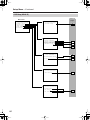 84
84
-
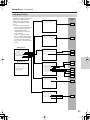 85
85
-
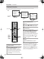 86
86
-
 87
87
-
 88
88
-
 89
89
-
 90
90
-
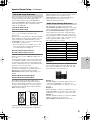 91
91
-
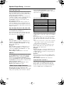 92
92
-
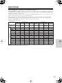 93
93
-
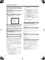 94
94
-
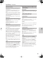 95
95
-
 96
96
-
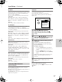 97
97
-
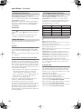 98
98
-
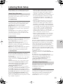 99
99
-
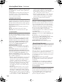 100
100
-
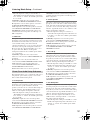 101
101
-
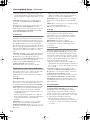 102
102
-
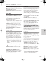 103
103
-
 104
104
-
 105
105
-
 106
106
-
 107
107
-
 108
108
-
 109
109
-
 110
110
-
 111
111
-
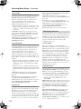 112
112
-
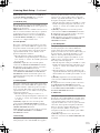 113
113
-
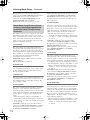 114
114
-
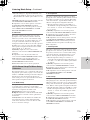 115
115
-
 116
116
-
 117
117
-
 118
118
-
 119
119
-
 120
120
-
 121
121
-
 122
122
-
 123
123
-
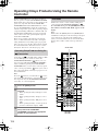 124
124
-
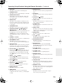 125
125
-
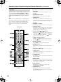 126
126
-
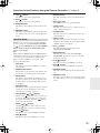 127
127
-
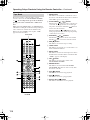 128
128
-
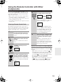 129
129
-
 130
130
-
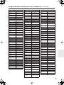 131
131
-
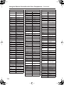 132
132
-
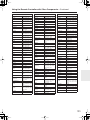 133
133
-
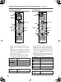 134
134
-
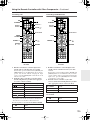 135
135
-
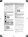 136
136
-
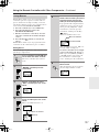 137
137
-
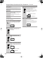 138
138
-
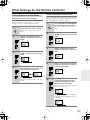 139
139
-
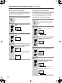 140
140
-
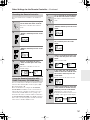 141
141
-
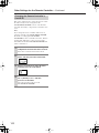 142
142
-
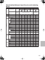 143
143
-
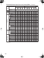 144
144
-
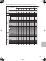 145
145
-
 146
146
-
 147
147
-
 148
148
-
 149
149
-
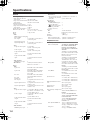 150
150
-
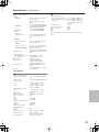 151
151
-
 152
152


Ask a question and I''ll find the answer in the document
Finding information in a document is now easier with AI
Related papers
Other documents
-
Sony DAV-FR9 User manual
-
Eltax AVR-320 User manual
-
Pioneer Elite VSX-59TXi User manual
-
Sherwood SD-871 User manual
-
-
Marantz Slim-line NR1501 User manual
-
LG ARX9000 Owner's manual
-
Samsung SPS-210 User manual
-
Optoma MCA30 User manual
-
JVC VCR HM-DH5U User manual