Page is loading ...

CAUTION
Read all precautions and instruc-
tions in this manual before
using this equipment. Save this
manual for future reference.
• Assembly
• Adjustments
• Troubleshooting
• Part List and Drawing
Serial Number Decal (under seat)
Model No. 831.15407.0
S
erial No.
Write the serial number in the
s
pace above for future reference.
WEIGHT SYSTEM EXERCISER
User’s Manual
Sears, Roebuck and Co., Hoffman Estates, IL 60179

2
IMPORTANT PRECAUTIONS . . . . . . . . . . . . . . . . . . . . . . . . . . . . . . . . . . . . . . . . . . . . . . . . . . . . . . . . . . . . . . . . 3
WARNING DECAL PLACEMENT . . . . . . . . . . . . . . . . . . . . . . . . . . . . . . . . . . . . . . . . . . . . . . . . . . . . . . . . . . . . . 4
B
EFORE YOU BEGIN . . . . . . . . . . . . . . . . . . . . . . . . . . . . . . . . . . . . . . . . . . . . . . . . . . . . . . . . . . . . . . . . . . . . . . 5
A
SSEMBLY . . . . . . . . . . . . . . . . . . . . . . . . . . . . . . . . . . . . . . . . . . . . . . . . . . . . . . . . . . . . . . . . . . . . . . . . . . . . . . .6
ADJUSTMENTS . . . . . . . . . . . . . . . . . . . . . . . . . . . . . . . . . . . . . . . . . . . . . . . . . . . . . . . . . . . . . . . . . . . . . . . . . . 17
CONSOLE OPERATION . . . . . . . . . . . . . . . . . . . . . . . . . . . . . . . . . . . . . . . . . . . . . . . . . . . . . . . . . . . . . . . . . . . .21
TROUBLESHOOTING . . . . . . . . . . . . . . . . . . . . . . . . . . . . . . . . . . . . . . . . . . . . . . . . . . . . . . . . . . . . . . . . . . . . .23
EXERCISE GUIDELINES . . . . . . . . . . . . . . . . . . . . . . . . . . . . . . . . . . . . . . . . . . . . . . . . . . . . . . . . . . . . . . . . . . 24
ORDERING REPLACEMENT PARTS . . . . . . . . . . . . . . . . . . . . . . . . . . . . . . . . . . . . . . . . . . . . . . . . . .Back Cover
FULL 10-YEAR WARRANTY . . . . . . . . . . . . . . . . . . . . . . . . . . . . . . . . . . . . . . . . . . . . . . . . . . . . . . . . Back Cover
Note: A PART IDENTIFICATION CHART and a PART LIST/EXPLODED DRAWING are attached in the center of
this manual. Remove the PART IDENTIFICATION CHART and PART LIST/EXPLODED DRAWING before begin-
ning assembly.
TABLE OF CONTENTS

3
1. Read all instructions in this manual and all
w
arnings on the resistance system before
using the resistance system. Use the resist-
ance system only as described in this manual.
2. It is the responsibility of the owner to ensure
that all users of the resistance system are
adequately informed of all precautions.
3. The resistance system is intended for home
use only. Do not use the resistance system in
any commercial, rental, or institutional setting.
4. Keep the resistance system indoors, away
from moisture and dust. Place the resistance
system on a level surface, with a mat
beneath it to protect the floor or carpet. Make
sure that there is enough clearance around
the resistance system to mount, dismount,
and use the resistance system.
5. Make sure that all parts are properly tight-
ened each time the resistance system is
used. Replace any worn parts immediately.
6. Always make sure the two screws in the rope
clamps are fully tightened each time the
resistance system is used.
7. Keep children under 12 and pets away from
the resistance system at all times.
8. Keep hands and feet away from moving parts.
9. Always wear athletic shoes for foot protec-
tion while exercising.
10.
The resistance system is designed to sup-
port a maximum user weight of 300 pounds.
11. The top frame is not designed to be used for
p
ull-up exercises. Do not hang on the top
frame.
12. Pull on the lower cable only while sitting on
the bench or standing on the base plate. Pull
on the high cables only while sitting on the
bench, with the seat in one of the three posi-
tions closest to the upright base, or while
standing on the base plate.
13. The resistance system is designed to be
used with the included resistance, or the
resistance included with a WEIDER MAX
PACK. Do not use the resistance system with
any other type of resistance.
14. Always disconnect the lat bar from the high
cables when performing an exercise that
does not require it.
15. Make sure the storage knob is in place and
fully tightened each time the resistance sys-
tem is used.
16. Make sure that the cables remain on the pul-
leys at all times. If the cables bind as you are
exercising, stop immediately and make sure
that the cables are on the pulleys. Replace all
cables at least every two years.
17. Do not pull on the cables while the resist-
ance level is being adjusted.
18. If you feel pain or dizziness while exercising,
stop immediately and begin cooling down.
WARNING: Before beginning this or any exercise program, consult your physician. This
is especially important for persons over the age of 35 or persons with pre-existing health problems.
Read all instructions before using. Sears assumes no responsibility for personal injury or property
damage sustained by or through the use of this product.
WARNING: To reduce the risk of serious injury, read the following important precautions
before using the resistance system.
IMPORTANT PRECAUTIONS

4
WARNING DECAL PLACEMENT
The decals shown here have been
placed on the weight system. If a decal
is missing or illegible, please call toll-
f
ree 1-877-992-5999, Monday through
Friday, 6 a.m. until 6 p.m. Mountain
Time, and order a free replacement
decal. Apply the decal in the location
shown.
Keep hands and
fingers clear of
this area.

ASSEMBLED DIMENSIONS:
Height: 85 in. / 216 cm
Width: 47 in. / 119 cm
Depth: 94 in. / 239 cm
5
High Pulley
Squat Arm
Backrest
Storage Knob
Squat Backrest
Handle
Console
Top Frame
Low Pulley
Base Plate
Leg Lever
Curl Pad
Curl Bar
Seat
Squat Pin
Seat Knob
BEFORE YOU BEGIN
Thank you for selecting the innovative PLATINUM
PLUS BY WEIDER
®
resistance system. The resistance
system offers a selection of stations designed to devel-
o
p every major muscle group of the body. Whether your
goal is to tone your body, build dramatic muscle size
and strength, or improve your cardiovascular system,
the resistance system will help you to achieve the spe-
cific results you want.
For your benefit, read this manual carefully before
using the resistance system.
If you have questions
after reading this manual, call 1-800-4-MY-HOME
®
(1-800-469-4663). To help us assist you, please note
the product model number and serial number before
c
alling. The model number is 831.15407.0. The serial
number can be found on a decal attached to the resist-
ance system (see the front cover of this manual).
Before reading further, please review the drawing below
and familiarize yourself with the parts that are labeled.

6
Before beginning assembly, carefully read the
following information and instructions:
•
Assembly requires two persons.
• Place all parts in a cleared area and remove the
packing materials. Do not dispose of the packing
materials until assembly is completed.
•
For help identifying small parts, use the PART
IDENTIFICATION CHART.
Note: Some small
parts may have been pre-attached for shipping. If
a part is not in the parts bag, check to see if it
has been pre-attached.
• Tighten all parts as you assemble them, unless
instructed to do otherwise.
• A
s you assemble the resistance system, make
sure all parts are oriented as shown in the draw-
ings.
The included hex keys and the following
tools (not included) are required for assembly:
• Two adjustable wrenches
• One rubber mallet
• One standard screwdriver
• One Phillips screwdriver
• Lubricant, such as grease or petroleum jelly,
tape, and soapy water.
Assembly will be more convenient if you have a
socket set, a set of open-end or closed-end
wrenches, or a set of ratchet wrenches.
Make Things Easier for Yourself
This manual is designed to ensure that the resist-
ance system can be assembled successfully by
most people. However, it is important to realize
that the versatile resistance system has many
parts and that the assembly process will take
time. Most people find that by setting aside plenty
of time, assembly will go smoothly.
ASSEMBLY
1
1.
Attach four Plastic Base Feet (71) to the Base (1)
with four M4 Washers (157) and four M4 x 16mm
Self-tapping Screws (104).
Attach a Wheel (49) to the Base (1) with an M8 x
90mm Shoulder Bolt (125), two M8 W
ashers
(152), and an M8 Nylon Jamnut (139). Repeat
with the other Wheel.
Before beginning assembly, make sure that
you have read and understand the informa-
tion in the box above. Refer to the PART
IDENTIFICATION CHART for help identifying
small parts.
1
104
157
71
49
49
104
139
152
152
125
157
71
104
157
71
104
157
71

7
2. Insert two M14 x 155mm Bolts (107) through the
Right Arm Frame (171) and the Upright Base (2).
H
and tighten two M14 Nylon Locknuts (127) onto
the Bolts.
Insert two M10 x 65mm Carriage Bolts (103) up
through the Base (1).
Place a piece of tape over
the Bolt heads to hold them in place. Connect
the Upright Base (2) to the Base with the two
Carriage Bolts and two M10 Nylon Locknuts
(112). Do not tighten these Locknuts yet.
Connect the Upright Base (2) to the Base (1) with
two M10 x 67mm Bolts (111) and two M10 Nylon
Locknuts (112).
Fully tighten these Locknuts.
3. Set the Mech Frame (124) onto the Base (1)
behind the Upright Base. Hand tighten two M10 x
73mm Screws (137) and two M10 Washers (129)
into the indicated holes in the Base and Mech
Frame. Note: The Mech Frame will not be
shown in the following drawings for clarity.
Note: One end of the Rope (70) is connected
to the Right
Arm Frame (171).
Untie the loose
end of the Rope and route it through the Upright
Base (2). Make sure the loose end of the Rope
is still between the 90mm Thin Pulley (88) and
Cable Trap (78) (see the inset drawing), and
that it crosses under the connected end of the
Rope.
2
171
107
107
112
127
112
111
111
2
1
103
3
171
2
70
124
129
137
78
88
70
129
137
1

8
6
6. Remove the two M14 Nylon Locknuts (127).
Attach the Left
Arm Frame (8) to the Upright Base
(2) with the two M14 x 155mm Bolts (107) used in
step 2 and the two M14 Nylon Locknuts.
127
127
107
8
107
2
4. Route the loose end of the Rope (70) through the
Left Arm Frame (8) and a Swivel Arm (29). Make
s
ure the Rope is under the indicated rod in the
Swivel Arm.
Attach the Swivel Arm (29) to the Left Arm Frame
(8) with an M4 x 5mm Self-tapping Screw (176).
Attach a “V”-pulley (93) inside the Swivel Arm
(29) with an M10 x 53mm Button Bolt (140) and
an M10 Nylon Locknut (112).
70
29
8
2
93
176
140
112
Rod
169
166
Large
Hole
Grooves
165
70
5. Route the loose end of the Rope (70) through a
Rope Cover (169) and a Link (167) as shown.
Make sure the large hole in the Rope Cover is
on the side shown. Secure the set of Rope
Clamps (165, 166) on the Rope with two M5 x
16mm Button Screws (164). Make sure that
Rope is in the grooves of the Rope Clamps,
that there is 1/2" between the Link and the
Rope Clamps, and that the two Screws are fully
tightened. Slide the Rope Cover over the Rope
Clamps.
167
164
5
4

9
3
10
35
8. Attach the Squat Backrest (28) to the Squat
Carriage (10) with four M6 x 16mm Screws (108).
10
28
108
108
8
7. Attach the Backing Plate (59) to the Upright Base
(2) with two M10 x 65mm Carriage Bolts (103)
a
nd two M10 Nylon Locknuts (112). D
o not tight-
en the Locknuts yet.
103
112
2
59
7
9
9. Slide the Squat Carriage (10) onto the Upright (3)
as shown. Insert the Squat Pin (35) into an upper
hole in the Upright.

10
11
129
124
1
137
137
129
144
129
3
81
137
11. Insert an M10 x 125mm Button Screw (144)
through an M10 Washer (129), the Upright (3),
and the Backing Plate (not shown). Hold the Bolt
in place by sticking a piece of tape over the
bolt head.
Tighten the two M10 Nylon Locknuts (112)
used in step 7. T
ighten the two M10 x 20mm
Screws (1
13) and two M10 x 25mm Screws
(105) used in step 10.
Attach the Mech Frame (124) to the Base (1) with
two M10 x 73mm Bolts (137) and two M10
Washers (129). Do not tighten the Bolts yet.
Attach the Mech Frame (124) to the Upright (3)
with the M10 x 125mm Button Screw (144). Make
sure the Upright and Mech Frame are properly
aligned before tighten the Screw.
Tighten the four M10 x 73mm Bolts (137) in
the Base (1) and the two M10 Nylon Locknuts
(112) used in the second paragraph of step 2.
Snap the Side Mech Cover (81) into place on the
Mech Frame (124).
10
3
31
2
105
129
159
172
172
173
10. Press the Front Cover (31) onto the Upright Base
(2). Make sure the Cover is oriented as shown
i
n the inset drawing.
R
oute the Upper Wire Harness (172) down
through the Upright Base (2) and out the large
round hole in the back, as shown.
Slide the Upright (3) onto the Upright Base (2).
Make sure you do not pinch the Upper Wire
Harnesses (172). Secure the Upright with two
M10 Washers (129), two M10 x 20mm Screws
(113), and two M10 x 25mm Screws (105).
Do
not tighten the Screws yet.
Connect the Upper Wire Harness (172) to the
Lower Wire Harness (173) extending from the
Mech Frame (not shown). The connector should
slide easily into the socket and snap into place.
If the connector does not slide easily and snap into
place, turn it over and then insert it.
IF THE CON-
NECTOR IS NOT INSERTED PROPERLY, THE
CONSOLE MAY BE DAMAGED WHEN THE
POWER IS TURNED ON. Press the excess wire
into the Upright Base.
Tighten two M4 x 16mm White ZP Self-tapping
Screws (159) into the Upright (3).
113
159
3
1
Slots on bottom

11
14. Attach the Upright Plate (23) to the Upright (3)
with six M4 x 9mm Self-tapping Screws (106).
14
106
23
3
106
12. Wet a Squat Arm (18) and the inside of a Small
Foam Pad (36) with soapy water. Slide the Foam
P
ad onto the Squat Arm.
G
rease an M10 x 73mm Bolt (137). Attach a
Squat Arm (18) to the Squat Carriage (10) with
the Bolt, two 24mm Plastic Washers (110), and
an M10 Nylon Locknut (112). Do not overtighten
the Locknut; the Squat Arm should be able to
pivot with intermediate effort.
Repeat this step with the other Squat Arm
(18).
110
112
1
10
12
137
Grease
10
18
3
6
18
13. Orient the Top Frame (20) with the mark in the
position shown. Attach the Top Frame to the
Upright (3) with two M10 x 65mm Button Screws
(117) and two M10 Washers (129). Press the
Plastic Cap (46) into the Upright, over the Top
Frame.
13
46
20
117
129
3
Mark

12
15. Attach the Console (21) to the Upper Wire
Harness (172). The connector should slide easi-
l
y into the socket and snap into place. I
f a con-
nector does not slide easily and snap into place,
t
urn it over and then insert it.
I
F THE CONNEC-
TOR IS NOT INSERTED PROPERLY, THE CON-
SOLE MAY BE DAMAGED WHEN THE POWER
IS TURNED ON.
Push the excess wire into the
Upright (3).
Attach the Console (21) to the Upright (3) with
two M4 x 80mm Self-tapping Screws (145), two
M4 x 65mm Self-tapping Screws (158), and four
M4 Washers (157).
15
172
21
157
3
158
145
157
16
17
2
5
Attach at
this hole
Holes
19
44
112
16
. Orient the Rail (5) with the holes on the side
shown. Attach the Rail to the Upright Base (2)
with an M10 x 106mm Bolt (19) and an M10
Nylon Locknut (112). Do not overtighten the
Locknut; the Rail must be able to pivot
easily.
Tighten the Storage Knob (44) into the
Upright Base (2) and the Rail (5).
17
.
Orient the Seat (25) as shown.
Attach the Seat to
the Seat Carriage (16) with four M6 x 16mm
Screws (108).
25
Wide
End
16
108
108

13
19. Pull out the Seat Knob (138) as far as it will go,
and set the Seat Carriage (16) on the Bench Rail
(5).
Loosely attach two 8mm Spacers (123), a 59mm
Spacer (122), and two Seat Wheels (74) to the
bottom holes in the Seat Carriage (16) with an
M8 Nylon Jamnut (139) and an M8 x 102mm Bolt
(119).
Make sure the parts are oriented as
shown in the inset drawing.
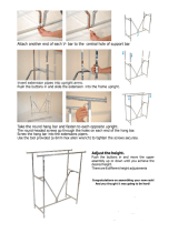
20. Make sure that the wide sides of all six Seat
Wheels (74) are pressed against the Rail (5).
While a second person presses down on the Seat
(25), hold the bottom Seat Wheels firmly against
the bottom of the Rail and properly tighten the
indicated M8 Nylon Jamnut (139). Do not over
-
tighten the Jamnut; the Wheels must be able
to roll across the Rail.
Engage the Seat Knob (138) into an adjustment
hole in the Rail (5).
18. Press the Front Leg Foot (38) onto the Front Leg
(4). Note: The front of the Front Leg Foot is
t
aller than the back of the Foot.
A
ttach the Front Leg (4) to the Rail (5) with four
M8 x 20mm Screws (95) and four M8 Washers
(152).
19
18
16
5
138
139
1
19
4
95
1
52
95
38
20
5
Front is
taller
74
74
139
138
74
74
25
5
152
122
123
123
74
74
Wide
Side

14
21. Attach the Leg Lever (13) to the Front Leg (4)
with a Leg Lever Pin (91) and a Cotter Pin (90).
23. Insert the two Short Pad Tubes (32) into the Leg
Lever (13). Slide two Large Foam Pads (37) onto
each Short Pad Tube.
Repeat this step with the Long Pad T
ube (153)
and the Front Leg (4).
22. See the inset drawing. Route the short end of
the Split Cable (72) through the Front Leg (4) and
attach it inside the Leg Lever (13) with a Leg
Lever Pin (91) and a Cotter Pin (90).
Attach a 90mm Pulley (92) inside the Front Leg
(4), over the Spit Cable (72), with an M10 x
92mm Bolt (116), two M10 Washers (129), two
25mm Spacers (130), and an M10 Nylon Locknut
(112).
21
22
23
13
91
13
72
91
90
4
129
129
112
130
92
72
130
32
32
153
4
37
13
37
116
4
9
0

15
24. Attach the Backrest Cap (40) to the Backrest
Frame (17) with two M4 x 16mm Self-tapping
S
crews (104).
A
ttach a Bumper (168) to the Backrest Frame
(17) with an M4 x 16mm Self-tapping Screw (104)
and an M4 Washer (157).
Attach the Right Pivot Guard (42) to the Backrest
Frame (17) with two M4 x 9mm Self-tapping
Screws (106). Attach the Left Pivot Guard (41)
in the same manner.
25. Attach the Backrest (24) to the Backrest Frame
(17) with four M6 x 38mm Screws (128) and four
M6 Washers (126).
26. Insert the rod on the Backrest Frame (17) into the
slot in the Seat Carriage (16). Hold the Backrest
Frame vertically over the Seat Carriage and
slide the rod into the slot, as shown in the
inset drawing.
24
25
41
42
17
106
1
68
157
1
04
40
17
24
126
126
128
128
26
17
16
17
16
104

16
27. Attach the Curl Pad (26) to the Curl Post (12) with
two M6 x 16mm Screws (108).
27
12
108
26
28
.
Make sure that all parts have been properly tightened. The use of the remaining parts will be explained in
ADJUSTMENTS, beginning on the next page.
Before using the resistance system, turn on the console and change the resistance setting as
described in CONSOLE OPERATION on page 21. Additional resistance may be purchased by calling
toll-free 1-877-992-5999 and asking for a model number WEMC0674.
An optional WEIDER CALF RAISE BLOCK may be purchased for use with your resistance system
by calling toll-free 1-877-992-5999 and asking for model number WEMC0474.

This section explains how to adjust the resistance system. See the EXERCISE GUIDELINES on page 24 for
important information about how to get the most benefit from your exercise program. Also, see the accompany-
i
ng exercise guide to see the correct form for each exercise.
Make sure all parts are properly tightened each time the resistance system is used. Replace worn parts immedi-
ately. The resistance system can be cleaned with a damp cloth and a mild, non-abrasive detergent. Do not use
solvents.
17
Ball
ATTACHING THE HIGH PULLEYS
To use a high pulley, slide the hook on the Pulley
Housing (27) onto a hook on the Top Frame (20).
Attach the end of the Short Cable (73) without the ball
to the end of the Rope (70) with a Cable Clip (161).
Attach the other high pulley in the same manner.
Remove the high pulleys when not in use.
A
TTACHING THE LEG LEVER
To use the Leg Lever (13), attach it to the Front Leg
(4) with a Leg Lever Pin (91) and a Cotter Pin (90).
Attach the Split Cable (72) inside the Leg Lever (13)
with a Leg Lever Pin (91) and a Cotter Pin (90).
See the inset drawing. Attach one of the long ends
of the Split Cable (72) to one end of the Rope (70)
with a Cable Clip (161). Attach the other long end
of the Split Cable to the other end of the Rope in
the same manner.
27
161
73
70
20
161
72
70
90
90
72
91
91
13
4
ADJUSTMENTS

18
84
ATTACHING THE ACCESSORIES
T
o attach a Short Handle (84) to a high pulley, first
attach the pulley housings to the resistance system
(
see ATTACHING THE HIGH PULLEYS on the previ-
ous page). Then, attach the Handle to a Short Cable
(73) with a Cable Clip (161).
The Long Handles (not shown) and the Ankle Strap
(not shown) can be attached to the Short Cables (73)
or the Rope (not shown) with Cable Clips (161). Attach
the Hip Strap (not shown) to the ends of the Rope with
two Cable Clips.
The Ab Strap (not shown) can be attached to the Rope
(not shown) using the two Extension Straps (not
shown) and four Cable Clips (161).
ATTACHING THE CURL PAD
To attach the Curl Pad (26), insert the Curl Post (12)
into the Front Leg (4). Secure the Curl Post with the
Curl Knob (45).
Remove the Curl Pad (26) from the resistance
system when performing an exercise that does
not require it.
ATTACHING THE CURL BAR
To use the Curl Bar (43), first attach the leg lever to
the front leg (see ATTACHING THE LEG LEVER on
the previous page). Attach the Curl Bar to the hook
on the Leg Lever (13).
73
1
61
73
45
12
26
4
43
13

24
17
16
Rod
Slot
5
16
2
ADJUSTING THE BACKREST
The Backrest (24) can be used in a level position or an
inclined position. To use the Backrest in a level posi-
tion, secure the Seat Carriage (16) at the adjustment
hole in the Rail (5) closest to the Front Leg (not shown)
(see ADJUSTING THE SEAT on the next page).
To use the Backrest (24) in an inclined position,
secure the Seat Carriage (16) at one of the other
adjustment holes in the Rail (5). Rest the Backrest
against the Upright Base (2) or the Upright (3). Note:
To use the Backrest in the most inclined position,
the Squat Pin (not shown) must hold the Squat
Carriage (not shown) in the highest position (see
ATTACHING THE SQUAT STATION below).
For row exercises, remove the Backrest Frame (17)
from the Seat Carriage (16). Hold the Backrest Frame
vertically over the Seat Carriage and lift the rod out of
the slot (see the inset drawing).
3
19
ADJUSTING THE SQUAT ARM
To adjust a Squat Arm (18), pull the Arm to the
desired position.
18
18
82
70
161
161
82
3
10
18
35
ATTACHING THE SQUAT STATION
To use the squat station, first remove the backrest
(see ADJUSTING THE BACKREST above). Next,
adjust the squat arm to the forward position (see
ADJUSTING THE SQUAT ARM above). Then, insert
a Squat Pin (35) into the correct hole in the Upright
(3). Finally, attach each end of the Rope (70) to the
Squat Carriage (10) with an Extension Strap (82) and
two Cable Clips (161).
Note: The Squat Pin (35) will determine the lowest
point to which the Squat Carriage (10) can
descend. The Squat Carriage should not be able to
descend so low that the user could become
trapped under the Squat Arms (18).

20
2
3
4
1
5
20
44
STORING THE RESISTANCE SYSTEM
To store the resistance system, first remove the Curl
Pad (not shown) and the Leg Lever (not shown) from
the resistance system. Secure the Seat (25) at the
position closest to the Front Leg (4) (see ADJUSTING
THE SEAT above). Next, remove the Storage Knob
(44) from the Upright Base (2). Lift the Front Leg
toward the Top Frame (20). Tighten the Storage Knob
into the side of the Upright Base and into the Rail (5).
To move the resistance system, stand behind the
Upright (3) and place the toe of your shoe on the end
of the Base (1). Tilt the resistance system back onto
the Wheels (49) and roll it to the new location.
WARNING: Make sure that the
Storage Knob (44) is in place and fully tight-
ened each time the resistance system is used.
25
49
ADJUSTING THE SEAT
T
he Seat (25) can be secured at various positions on
the Rail (5). To move the Seat, pull the Seat Knob
(
138) out as far as it will go and slide the Seat to the
desired position. Engage the Seat Knob into an
adjustment hole in the Rail.
To perform row exercises, the hip strap must be
attached to the rope (see ATTACHING THE ACCES-
SORIES on page 18), and the Seat Carriage (16)
must be able to roll along the Rail (5). First, remove
the backrest from the seat carriage (see ADJUSTING
THE BACKREST on page 19). Then, pull the Seat
Knob (138) out as far as it will go, and turn the Seat
Knob so that the pin rests at the end of the “L”-
shaped slot (see the inset drawing).
16
2
5
5
16
138
Pin
“L”-Slot
Adjustment
Hole
138
/