Kenmore 30 gal. Mobile Home Natural Gas Water Heater Installation guide
- Category
- Water heaters & boilers
- Type
- Installation guide
This manual is also suitable for

1
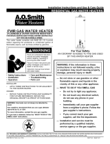
®
Use & Care Guide
Model No.
153.336930 30 Gallon Tall
153.336940 40 Gallon Tall
Kenmore®
Gas Water Heater
For potable water heating only.
Not suitable for space heating.
For use only in mobile homes.
This water heater shall not be installed in
the occupied space of the manufactured
(mobile) home.
INSTALLER: Affix these instructions to or
near the water heater.
OWNER: Retain these instructions for future
reference.
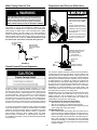
FOR YOUR SAFETY: An odorant is added to
the gas used by this water heater.
Si no puede leer o entender el inglés y necesita el manual de
instrucciones en español, puede solicitarlo al 1-800-821-2017. NO
TRATE DE INSTALAR U OPERAR ESTE CALENTADOR DE AGUA
SI NO ENTIENDE LAS INSTRUCCIONES. No hacer caso de esta
advertencia podría originar lesiones graves o mortales.
ADVERTENCIA
P/N 321634-001 (0512)
Sears Brands Management Corporation,
Hoffman Estates, IL 60179 U.S.A.
www.kenmore.com
www.sears.com
LOW LEAD
CONTENT

2
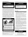
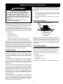
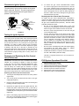
Flammable Vapors
FLAMMABLES
FIRE AND EXPLOSION HAZARD
Can result in serious injury or death
Do not store or use gasoline or other
flammable vapors and liquids in the vicinity of this
or any other appliance. Storage of or use of
gasoline or other flammable vapors or liquids in the
vicinity of this or any other appliance can result in
serious injury or death.
Read and follow water heater warnings and instructions.
WARNING
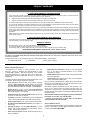
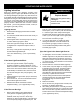
Your safety and the safety of others is extremely important in the installation, use and servicing of this water heater.
Many safety-related messages and instructions have been provided in this manual and on your own water heater to warn you and others of
a potential injury hazard. Read and obey all safety messages and instructions throughout this manual. It is very important that the meaning
of each safety message is understood by you and others who install, use or service this water heater.
This is the safety alert symbol. It is used to alert you to potential personal injury hazards.
Obey all safety messages that follow this symbol to avoid possible injury or death.
DANGER indicates an imminently hazardous situation which, if not avoided, will
result in death or injury.
WARNING indicates a potentially hazardous situation which, if not avoided, could result
in death or injury.
CAUTION indicates a potentially hazardous situation which, if not avoided, could result
in minor or moderate injury.
CAUTION used without the safety alert symbol indicates a potentially hazardous
situation which, if not avoided, could result in property damage.
All safety messages will generally tell you about the type of hazard, what can happen if you do not follow the safety message and
how to avoid the risk of injury.
The California Safe Drinking Water and Toxic Enforcement Act requires the Governor of California to publish a list of substances known to
the State of California to cause cancer, birth defects, or other reproductive harm, and requires businesses to warn of potential exposure
to such substances. WARNING: This product contains a chemical known to the State of California to cause cancer, birth defects, or other
reproductive harm. This appliance can cause low-level exposure to some of the substances included in the act.
This product is certifi ed to comply with a maximum weighted average of 0.25% lead content as required in some areas.
IMPORTANT DEFINITIONS
• Qualifi ed Technician: A qualifi ed technician must have ability equivalent to a licensed tradesman in the fi elds of plumbing, air supply,
venting, and gas supply, including a thorough understanding of the requirements of the National Fuel Gas Code as it relates to the
installation of gas fi red water heaters. The qualifi ed technician must also be familiar with the design features and use of fl ammable vapor
ignition resistant water heaters, and have a thorough understanding of this instruction manual.
• Service Agency: A service agency also must have ability equivalent to a licensed tradesman in the fi elds of plumbing, air supply, venting
and gas supply, including a thorough understanding of the requirements of the National Fuel Gas Code as it relates to the installation of
gas fi red water heaters. The service agency must also have a thorough understanding of this instruction manual, and be able to perform
repairs strictly in accordance with the service guidelines provided by the manufacturer.
• Gas Supplier: The natural gas or propane utility or service who supplies gas for utilization by the gas burning appliances within this
application. The gas supplier typically has responsibility for the inspection and code approval of gas piping up to and including the natural
gas meter or propane storage tank of a building. Many gas suppliers also offer service and inspection of appliances within the building.
© Sears Brands Management Corporation
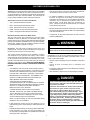
SAFE INSTALLATION, USE AND SERVICE
SAFETY PRECAUTIONS

3
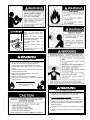
Fire or Explosion Hazard
Do not store or use gasoline or other flammable vapors and
liquids in the vicinity of this or any other appliance.
Avoid all ignition sources if you smell Natural or LP gas.
Do not expose water heater control to excessive gas
pressure.
Use only gas shown on rating plate unless the water heater
has been properly converted.
Maintain required clearances to combustibles.
Keep ignition sources away from faucets after extended
period of non-use.
Read instruction manual before
installing, using or servicing
water heater.
Follow conversion instructions listed in manual when
converting to opposite gas.
Fire or Explosion Harzard
Hydrogen gas can be produced in a hot water system after
a period of non-use (generally two or more weeks).
Hydrogen gas is extremely flammable and can ignite.
After an extended period of non-use, purge gases from hot
water system. To return hot water system to service, open a
hot water faucet in kitchen for several minutes before using
electrical appliances.
Do not smoke or have open flame near faucet while it is open.
Leave hot water faucet open until the sound of escaping
air stops.
Water temperature over 125°F
(52°C) can cause servere burns
instantly resulting in severe injury or
death.
Children, the elderly, and the
physically or mentally disabled are at
highest risk for scald injury.
Feel water before bathing or
showering.
Temperature limiting valves are
available.
Read instruction manual for safe
temperature setting.

4
TABLE OF CONTENTS
SAFE INSTALLATION, USE AND SERVICE ................................................................................................. 2
SAFETY PRECAUTIONS ........................................................................................................................... 2-3
PRODUCT WARRANTY ................................................................................................................................ 6
CUSTOMER RESPONSIBILITIES ................................................................................................................. 7
PRODUCT SPECIFICATIONS ...................................................................................................................... 8
MATERIALS AND BASIC TOOLS NEEDED .................................................................................................. 9
TYPICAL INSTALLATION ............................................................................................................................ 10
IMPORTANT INFORMATION ABOUT THIS WATER HEATER ....................................................................11
Installation Checklist ................................................................................................................................................11
INSTALLATION INSTRUCTIONS ........................................................................................................... 12-15
Removing the Old Water Heater ............................................................................................................................. 12
Location Requirements ........................................................................................................................................... 13
Site Location ...................................................................................................................................................... 13-14
Securing Water Heater to Floor and Wall ............................................................................................................... 14
Insulation Blankets ............................................................................................................................................. 14-15
Clearances and Accessibility .................................................................................................................................. 15
Filling the Water Heater .......................................................................................................................................... 15
GAS CONVERSION ..................................................................................................................................... 16
GAS SUPPLY .......................................................................................................................................... 17-18
Gas Requirements .................................................................................................................................................. 17
Gas Piping .............................................................................................................................................................. 17
Gas Pressure .......................................................................................................................................................... 17
Gas Pressure Testing.............................................................................................................................................. 17
LP Gas Only............................................................................................................................................................ 18
COMBUSTION AIR SUPPLY & VENTILATION ...................................................................................... 19-20
Vent Pipe System ................................................................................................................................................... 19
Draft Hood Installation ............................................................................................................................................ 19
Roof Jack Installation .............................................................................................................................................. 19
Enclosure Installation .............................................................................................................................................. 20
WATER SYSTEM PIPING ....................................................................................................................... 21-23
Piping Installation .................................................................................................................................................... 21
Water Piping Pressure Test .................................................................................................................................... 22
Closed System/Thermal Expansion ........................................................................................................................ 22
Temperature and Pressure Relief Valve ................................................................................................................. 22
T&P Relief Valve and Pipe Insulation ........................................................................................................................ 23
OPERATING YOUR WATER HEATER ................................................................................................... 24-27
Lighting Instructions ........................................................................................................................................... 24-25
Checking the Draft .................................................................................................................................................. 26
Burner Flames ........................................................................................................................................................ 26
Emergency Shut Down ........................................................................................................................................... 26
Water Temperature Regulation .......................................................................................................................... 26-27
Operating the Temperature Control System ........................................................................................................... 27

5
SERVICE AND ADJUSTMENT ......................................................................................................... 28-30
Vent System Inspection .......................................................................................................................................... 28
Burner Inspection .................................................................................................................................................... 28
Burner Cleaning ...................................................................................................................................................... 28
Housekeeping ......................................................................................................................................................... 29
Anode Rod Inspection ............................................................................................................................................ 29
Temperature-Pressure Relief Valve Operation ....................................................................................................... 29
Draining and Flushing ............................................................................................................................................. 30
Service .................................................................................................................................................................... 30
MAINTENANCE OF YOUR WATER HEATER ........................................................................................ 31-33
Replacement Parts ................................................................................................................................................. 31
Removing the Manifold/Burner Assembly ............................................................................................................... 31
Removing the Burner from the Manifold/Burner Assembly .................................................................................... 31
Replacing the Pilot/ Thermopile Assembly ........................................................................................................ 31-32
External Inspection & Cleaning of the Base-Ring Filter ......................................................................................... 32
Cleaning the Combustion Chamber and Flame-arrestor ........................................................................................ 33
Replacing the Manifold/Burner Assembly ............................................................................................................... 33
Piezoelectric Igniter System ................................................................................................................................... 34
Testing the Igniter System ...................................................................................................................................... 34
Removing and Replacing the Gas Control Valve/Thermostat ................................................................................ 34
FVIR System Operational Checklist ....................................................................................................................... 34
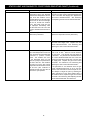
TROUBLESHOOTING GUIDE ................................................................................................................ 35-37
Start Up Conditions ............................................................................................................................................ 35-36
Operational Conditions ...................................................................................................................................... 36-37
TROUBLESHOOTING CHECKLIST ....................................................................................................... 38-39
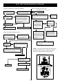
PILOT LIGHT TROUBLESHOOTING FLOWCHART ................................................................................... 40
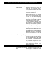
STATUS LIGHT AND DIAGNOSTIC CODE TROUBLESHOOTING CHART ......................................... 41-42
PARTS ORDER LIST ................................................................................................................................... 43

6
The price of your water heater does not include a free checkup service call. On water heater installations arranged by Sears, Sears
warrants the installation.
A charge will be made on service calls due to poor or incomplete installation. These include:
a. Adjusting thermostat b. Condensation c. Leaks in pipes or fi ttings
Master Protection Agreements
Congratulations on making a smart purchase. Your new
Kenmore
®
product is designed and manufactured for years
of dependable operation. But like all products, it may require
preventive maintenance or repair from time to time. That’s when
having a Master Protection Agreement can save you money and
aggravation.
The Master Protection Agreement also helps extend the life of your
new product. Here’s what the Agreement* includes:
• Parts and labor needed to help keep products operating
properly under normal use, not just defects. Our coverage
goes well beyond the product warranty. No deductibles, no
functional failure excluded from coverage— real protection.
• Expert service by a force of more than 10,000 authorized
Sears service technicians, which means someone you can
trust will be working on your product.
• Unlimited service calls and nationwide service, as often as
you want us, whenever you want us.
• “No-lemon” guarantee – replacement of your covered product
if four or more product failures occur within twelve months.
• Product replacement if your covered product can’t be fixed.
• Annual Preventive Maintenance Check at your request – no
extra charge.
• Fast help by phone – we call it Rapid Resolution – phone
support from a Sears representative on all products. Think of
us as a “talking owner’s manual.”
• Power surge protection against electrical damage due to
power fluctuations.
• $250 Food Loss Protection annually for any food spoilage
that is the result of mechanical failure of any covered
refrigerator or freezer.
• Rental reimbursement if repair of your covered product takes
longer than promised.
• 10% discount off the regular price of any non-covered repair
service and related installed parts.
Once you purchase the Agreement, a simple phone call is all that it
takes for you to schedule service. You can call anytime day or night,
or schedule a service appointment online.
The Master Protection Agreement is a risk free purchase. If you
cancel for any reason during the product warranty period, we
will provide a full refund. Or, a prorated refund anytime after the
product warranty period expires. Purchase your Master Protection
Agreement today!
Some limitations and exclusions apply. For prices and additional
information in the U.S.A. call 1-800-827-6655.
* Coverage in Canada varies on some items. For full details,
call Sears Canada at 1-800-361-6665.
Sears Installation Service
For Sears professional installation of home appliances, garage door
openers, water heaters, and other major home items, in the U.S.A.
or Canada call 1-800-4-MY-HOME
®
.
PRODUCT WARRANTY
6 - YEAR LIMITED WARRANTY ON WATER HEATER
For six years from the date of purchase, if this water heater is installed and operated in a single-family home in accordance with the
owner’s manual instructions and all local applicable plumbing codes, Sears will:
1. Supply free water heater parts for those that are defective in material or workmanship.
2. Supply a free water heater for one that develops a tank leak. See notes below also.
For the second through sixth year from the purchase date, you must pay the labor cost for installation of parts or water heater.
For commercial, institutional, industrial or residential use by two or more families, the above limited warranty is only for two years. During
the second year you must pay the labor cost for parts or water heater installation.
If governmental regulations prohibit Sears from furnishing a comparable model replacement water heater under this warranty, Sears will
furnish a new water heater of comparable output as permitted by such governmental regulations; however, the Owner will be charged
for the additional cost associated with the changes made to the replacement water heater design to comply with such governmental
regulations.
Replacements and/or repairs furnished under this warranty do not carry a new warranty, and are only covered by the unexpired portion
of the original warranty.
1 - YEAR EXCLUSIVE KENMORE LABOR WARRANTY
For the first year from the date of purchase, Sears will, free of charge, supply and install new water heater parts for defective ones or a
new water heater for one that develops a leak.
WARRANTY SERVICE
To obtain warranty service, call 1-800-4-MY-HOME
®
(1-800-469-4663).
This warranty applies only while this product is in use in the United States.
This warranty gives you speci c legal rights, and you may also have other rights which vary from state to state.
SEARS BRANDS MANAGEMENT CORPORATION, Hoffman Estates, IL 60179

7
CUSTOMER RESPONSIBILITIES
Thank You for purchasing a Kenmore water heater. Properly installed
and maintained, it should give you years of trouble free service. If
you should decide that you want the new water heater professionally
installed by Sears call 1-800-4-MY-HOME
®
. They will arrange for
prompt, quality installation by Sears authorized contractors.
Abbreviations Found In This Instruction Manual:
• CSA - Canadian Standards Association
• ANSI - American National Standards Institute
• NFPA - National Fire Protection Association
• ASME - American Society of Mechanical Engineers
• GAMA - Gas Appliance Manufacturers Association
Important Information About This Water Heater:
This gas water heater was manufactured to voluntary safety
standards to reduce the likelihood of a fl ammable vapor ignition
incident. New technology used in meeting these standards makes this
product more sensitive to installation errors or improper installation
environments. Please review the Installation Checklist and make
any required installation upgrades or changes.
IMPORTANT: This water heater is shipped from the factory as a
natural gas unit. However, it may be converted to use LP gas. See
the Gas Conversion section for more information.
This manual contains instructions for the installation, operation,
and maintenance of the gas-fi red water heater. It also contains
warnings through out the manual that you must read and be aware
of. All warnings and all instructions are essential to the proper
operation of the water heater and your safety. Since we cannot put
everything on the fi rst few pages, READ THE ENTIRE MANUAL
BEFORE ATTEMPTING TO INSTALL OR OPERATE THE WATER
HEATER.
• The installation must conform with these instructions and the
local code authority having jurisdiction. In the absence of local
and state codes, installations shall comply with the
“National
Fuel Gas Code,” ANSI Z223.1 (NFPA 54) -current edition.
Manufactured home manufacturers: The installation must
conform to “The Manufactured Home Construction and
Safety Standard, Title 24 CFR, Part 3280.”
These publications are available as follows:
The “National Fuel Gas Code” is available through The Canadian
Standards Association, 8501 East Pleasant Valley Rd, Cleveland,
Ohio 44131 or The National Fire Protection Association, 1
Batterymarch Park, Quincy, MA 02269.
“The Manufactured Home Construction and Safety
Standard, Title 24 CFR, Part 3280” is available through
The U.S. Department of Housing and Urban Development
(HUD), 451 7th Street S.W., Washington, DC 20410. Offi ces
are also located throughout the United States.
Check your phone listings for the local authorities having
jurisdiction over your installation.
• If after reading this manual you have any questions or do not
understand any portion of the instructions, call the Sears Service
Center.
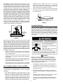
• Carefully plan the place where you are going to put the water heater.
Correct combustion, vent action, and vent pipe installation are
very important in preventing death from possible carbon monoxide
poisoning and fi res. See Figure 1.
• Examine the location to ensure the water heater complies with
the Installation Instructions section in this manual.
• For California installation, this water heater must be braced,
anchored, or strapped to avoid falling or moving during an
earthquake. See instructions for correct installation procedures.
Instructions may be obtained from California’s Offi ce of the
State Architect, 1102 Q Street, Suite 5100, Sacramento, CA
95811. Instructions can also be downloaded to your computer
at www.dsa.dgs.ca.gov/Pubs.
• Massachusetts Code requires this water heater to be installed in
accordance with Massachusetts 248-CMR 2.00: State Plumbing
Code and 248-CMR 5.00.
• Complies with 40 Ng/J NOx requirements of Texas and most
California AQM Districts.
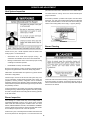
Excessive Weight Hazard
WARNING
Use two or more people to move and install the water heater.
Failure to do so can result in injury (including back injury).
IMPORTANT: Do not remove any permanent instructions, labels, or
the data label from either the outside of the water heater or on the
inside of water heater panels.
• Remove exterior packaging and place installation components
aside.
• Inspect all parts for damage prior to installation and
start-up.
• Completely read all instructions before attempting to assemble
and install this product.
• After installation, dispose of/recycle all packaging materials.
DANGER
Do not use this water heater with any gas other than the
one listed on the data plate unless the water heater has
been properly converted.
Refer to the “Gas Conversion” section of this manual to
convert from one gas to another. Failure to use the
correct gas can cause problems which can result in
death, serious bodily injury or property damage. If you
have any questions or doubts, consult your gas supplier
or gas utility company. Water heaters using bottled
propane or liquefied petroleum gas (LPG) are different
from natural gas models. A natural gas water heater will
not function safely on bottled propane or liquefied
petroleum gas (LPG) and a propane gas water heater will
not function safely on natural gas.

8
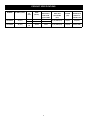
PRODUCT SPECIFICATIONS
MODEL
NUMBER
TANK CAPACITY
IN GALS (LTRS)
TYPE
OF
GAS
INPUT
RATE
(Btu/hr)
RECOVERY
RATE GALS.
PER HOUR
@ 90°F RISE
MINIMUM
VENT PIPE
DIA. INCHES
(mm)
DIAMETER
INCHES
(mm)
DIMENSIONS
INCHES (mm)
HEIGHT TO
JACKET TOP
153.336930 30 (113)
Natural 35,500 36.34
3 (76) OR 4 (102) 18 (457) 58 (1473)
LP 32,000 32.75
153.336940 40 (151)
Natural/
LP
35,500 36.34 3 (76) OR 4 (102) 20 (508) 58.25 (1480)

9
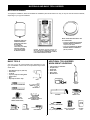
MATERIALS AND BASIC TOOLS NEEDED
MATERIALS NEEDED
To simplify the installation, Sears has available the installation parts shown below. You may or may not need all of these materials,
depending on your type of installation.
WATER HEATER INSTALLATION KIT
WITH FLEXIBLE CONNECTORS FOR 3/4”
(19.05 mm) COPPER PLUMBING AND FLEXIBLE
GAS CONNECTOR WITH FITTINGS.
EXPANSION TANKS FOR
THERMAL EXPANSION
CONDITIONS AVAILABLE
IN 2 GALLONS
(7.6 LITERS) AND
5 GALLONS (18.9 LITERS)
CAPACITY THROUGH
LOCAL SEARS STORE
OR SERVICE CENTER.
METAL DRAIN PANS AVAILABLE IN THE
FOLLOWING SIZES:
• 20” (508 mm) DIAMETER FOR WATER
HEATERS HAVING A DIAMETER OF
18” (457 mm) OR LESS.
• 24” (610mm) DIAMETER FOR WATER
HEATERS HAVING A DIAMETER 22”
(559 mm) OR LESS.
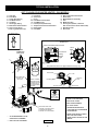
BASIC TOOLS
You may or may not need all these tools, depending on your
type of installation. These tools can be purchased at your local
Sears Store.
• Pipe Wrenches (2) 14” (356 mm)
• Screwdriver
• Tin Snips
• 6’ (1.82 m) Tape or Folding Ruler
• Garden Hose
• Drill
• Pipe Dope or Tefl on
®
Tape
ADDITIONAL TOOLS NEEDED
WHEN SWEAT SOLDERING
• Tubing Cutters or Hacksaw
• Propane Torch
• Soft Solder
• Solder Flux
• Emery Cloth
• Wire Brushes
SLOT-HEAD SCREWDRIVER
PHILLIPS SCREWDRIVER
TIN SNIPS
PIPE WRENCH
PIPE DOPE
(SQUEEZE TUBE)
USE FOR WATER AND GAS
CONNECTIONS
DRILL
GARDEN HOSE
6 FOOT TAPE
ROLL OF TEFLON
®
TAPE (USE ONLY ON
WATER CONNECTIONS)
HACKSAW
3/4” (19 mm) WIRE BRUSH
1/2” (13 mm) WIRE BRUSH
SOLDER
FLUX
ROLL OF LEAD-FREE
SOFT SOLDER
TUBING CUTTER
PROPANE
TORCH
ROLL OF
EMERY CLOTH

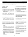
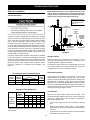
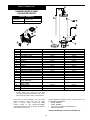
10
N
A
B
D
F
G
H
I
W
V
U
T
R
J
K
Q
M
L
E
P
Y
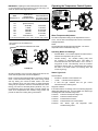
(U) MANIFOLD/BURNER ASSEMBLY
DISCHARGE PIPE
(DO NOT CAP
OR PLUG.)
(S) GAS CONTROL VALVE/
THERMOSTAT
DRAIN LINE MUST PASS
THROUGH THE STRUCTURAL
FLOOR AND DISCHARGE
EXTERNAL TO THE BUILDING
TO VENT
TERMINATION
(ROOF JACK)
(Z) ROOF JACK**
VAC
Igniter
Gas Control/Temperature Knob
120°F
Mark
Temperatures shown are approximates and may vary.
Conversion
Fitting
MANIFOLD
TUBE
IGNITER WIRE
MAIN BURNER
PILOT TUBE
THERMOPILE
MANIFOLD DOOR
Status
Light
X
S
VACUUM RELIEF
VALVE*
INSTALL PER
LOCAL CODES
INSTALL THERMAL
EXPANSION TANK
IF WATER HEATER
IS INSTALLED IN
A CLOSED WATER
SYSTEM*
A Vent Pipe
B Draft Hood
C Anode (Not Shown)
D Hot Water Outlet
E Insulation
F Gas Supply Piping
G Manual Gas Shut-off Valve
H Ground Joint Union
I Drip Leg (Sediment Trap)
Z
GET TO KNOW YOUR WATER HEATER - GAS MODELS
J Inner Door
K Outer Door
L Union
M Inlet Water Shut-off Valve
N Cold Water Inlet
O Inlet Dip Tube (Not Shown)
P Temperature-Pressure Relief Valve
Q Rating Plate
S Gas Control Valve/Thermostat
T Drain Valve
U Manifold/Burner Assembly
V Flue
W Metal Drain Pan
X Piezo Igniter (bottom, Left-hand
Side of Gas Control Valve/Thermostat)
Y
Base-Ring Filter
Roof Jack
R Flue Baffle
TYPICAL INSTALLATION
* ALL PIPING MATERIALS TO BE
SUPPLIED BY CUSTOMERS.
** ROOF JACK NOT FURNISHED.
FIGURE 1.
* INSTALL IN ACCORDANCE
WITH LOCAL CODES.
* DRIP LEG AS REQUIRED
BY LOCAL CODES.
* SECURE WATER HEATER TO
FLOOR AND WALL AS DESCRIBED
IN THIS MANUAL.
* INSTALLATION SHOULD COMPLY
WITH THE “ENCLOSURE
INSTALLATION” SECTION OF THIS
MANUAL.

11
This gas water heater was manufactured to voluntary safety standards to reduce the likelihood of a flammable vapor ignition incident.
The new technology used in meeting these standards makes this product more sensitive to installation errors. Please review the
following checklist and make any required installation upgrades or changes.
Questions? Contact Sears at 1-800-4-MY-HOME (1-800-469-4663).
IMPORTANT INFORMATION ABOUT THIS WATER HEATER
Installation Checklist
Water Heater Location
Water heater location is important and can affect system
performance. Please check the following:
□ Installation area free of corrosive elements and flammable
materials.
□ Centrally located with the water piping system (For new
installations). Located as close to the gas piping and vent
pipe system as possible.
□ Located indoors and in a vertical position. Protected from
freezing temperatures.
□ Proper clearances from combustible surfaces
maintained and not installed directly on a carpeted floor.
□ Provisions made to protect the area from water damage.
Metal drain pan installed and piped to an adequate drain.
□ Sufficient room to service the water heater. See Clearances
and Accessibility section of this manual.
□ Water heater not located near an air moving device.
□ Is the installed environment dirty (excessive amounts of
lint, dirt, dust, etc.)? If so, the base-ring filter located on
the bottom of the water heater will need to be cleaned
periodically. Refer to the “Maintenance of your Water
Heater” section of this manual for information on cleaning
the base-ring filter.
Combustion Air Supply and Ventilation
Check for sufficient combustion air supply. Insufficient air for
the combustion of gas will result in the flame becoming “lazy”,
thereby allowing heat to build up in the combustion chamber.
This excessive heat will cause a thermal switch on the door
assembly to trip. Is the water heater installed in a closet or other
small, enclosed space? If so:
□ Are there openings for make-up air to enter and exit the
room/area?
□ Are the openings of sufficient size? Remember, if there
are other gas-fired or air-consuming appliances in the
same room, you need more make-up air. Refer to the
“Installation Instructions” and “Combustion Air Supply and
Ventilation” sections for specific requirements.
□ Make sure that fresh air is not taken from areas that contain
negative pressure producing devices such as exhaust fans,
dryers, fireplaces, etc.
□ Is there a furnace/air handler in the same room space as
the water heater? If so, has a return air duct system been
attached that exits the room? If so, check for leaks on the
air duct system. If no air duct system is present, correct
immediately by contacting a local Heating, Ventilation, Air-
Conditioning & Refrigeration (HVAC-R) authorized service
provider.
□ Use a fresh air supply that is free of corrosive elements and
flammable vapors.
□ Fresh air openings must be sized correctly with consideration
given to the blocking effect of louvers and grilles.
Vent Pipe System
Check for proper drafting at the water heater draft hood. Refer
to the “Checking the Draft” section of this manual for the test
procedure. If the procedure shows insufficient draft is present,
please check the following:
□ Draft hood properly installed.
□ Vent connectors securely fastened with screws and
supported properly to maintain six inch clearance.
□ Vent connector made of approved material and sized
correctly.
□ Vent pipe system installed according to all local and state
codes or, in the absence of local and state codes, the
“National Fuel Gas Code”, ANSI Z223.1 (NFPA 54)-current
edition. Manufactured home manufacturers must conform
with the “Manufactured Home Construction and Safety
Standard, Title 24 CFR, Part 3280.”
□ Flue baffle properly positioned in the flue tube.
□ Check the vent system for restrictions/obstructions and
check the vent termination height. Refer to the “Combustion
Air Supply and Ventilation” section of this water heater
manual for specific requirements.
□ Recheck for sufficient combustion air supply.
Water System Piping
□ Temperature and pressure relief valve properly installed
with a discharge line run to an adequate drain and protected
from freezing.
□ All piping properly installed and free of leaks.
□ Heater completely filled with water.
□ Closed system pressure build-up devices installed.
□ Mixing valve (when applicable) installed per manufacturer’s
instructions (See “Water Temperature Regulation” section).
Gas Supply and Piping
□ Gas type is the same as that listed on the water heater rating
plate unless the water heater has been properly converted.
Refer to the “Gas Conversion” section of this manual.
□ Gas line equipped with shut-off valve, union, and drip leg.
□ Use pipe joint compound or teflon tape marked as being
resistant to the action of petroleum [Propane (L.P.)] gases.
□ Adequate pipe size and approved pipe material.
□ An approved noncorrosive leak detection solution used
to check all connections and fittings for possible gas leaks.
Correct any leak found.

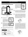
12
INSTALLATION INSTRUCTIONS
Removing the Old Water Heater
FIGURE 2.
1. Turn “OFF” the gas supply to
the water heater.
If the main gas line shutoff valve
serving all gas appliances is used,
also shut “OFF” the gas at each
appliance. Leave all gas appliances
shut “OFF” until the water heater
installation is completed. See
Figures 2 and 3.
2. Open a nearby hot water faucet
until the water is no longer hot.
When the water has cooled, turn
“OFF” the water supply to the water
heater at the water shut off valve
or water meter. Some installations
require that the water be turned off
to the entire house. See Figures 2
and 4.
3. Check again to make sure the gas supply is “OFF” to the water
heater. Then disconnect the gas supply connection from the
gas control valve.
4. Attach a hose to the water heater
drain valve and put the other end
in a fl oor drain or outdoors. (See
Figures 2 and 5.) Open the water
heater drain valve. The water
passing out of the drain valve
may be extremely hot. To avoid
being scalded, make sure all
connections are tight and that the
water fl ow is directed away from
any person.
5. Disconnect the vent pipe from the draft hood where it connects
to the water heater. In most installations the vent pipe can
be lifted off after any screw or other attached devices are
removed. Dispose of the draft hood. The new water heater
has a draft hood which must be used for proper operation.
6. If you have copper piping to the water heater, the two copper
water pipes can be cut with a hacksaw approximately four
inches away from where they connect to the water heater.
See Figure 6. This will avoid cutting off pipes too short.
Additional cuts can be made later if necessary. Disconnect the
temperature-pressure relief valve drain line. When the water
heater is drained, disconnect the hose from the drain valve.
Close the drain valve. The water heater is now completely
disconnected and ready to be removed.
FIGURE 6.
If you have galvanized pipes to the water heater, loosen
the two galvanized pipes with a pipe wrench at the union in
each line. Also disconnect the piping remaining to the water
heater. See Figure 7. These pieces should be saved since
they may be needed when reconnecting the new water heater.
Disconnect the temperature-pressure relief valve drain line.
When the water heater is drained, disconnect the hose from
the drain valve. Close the drain valve. The water heater
is now completely disconnected and ready to be removed.
Mineral buildup or sediment may have accumulated in the
old water heater. This causes the water heater to be much
heavier than normal and this residue, if spilled out, could
cause staining.
FIGURE 7.
FIGURE 3.
FIGURE 4.
FIGURE 5.
CHECK WITH
LOCAL UTILITY
FOR MINIMUM HEIGHT
3” MINIMUM
DRIP LEG
GROUND
JOINT
UNION
MANUAL GAS
SHUT-OFF VALVE
1
2
5
6
DISCHARGE PIPE
(DO NOT CAP
OR PLUG)
3
4
DRAIN LINE MUST PASS THROUGH FLOOR
AND TERMINATE EXTERNAL T
O
B
U
ILDIN
G

13
Location Requirements
Carbon Monoxide Poisoning Hazard
WARNING
Do not install this water heater in any occupied space of the
manufactured (mobile) home.
Doing so can result in carbon monoxide poisoning and death.
The FVIR System is designed to reduce the risk of flammable
vapor-related fires. The patented system protects your family by
trapping the burning vapors within the water heater combustion
chamber through the special flame-arrestor. The burning vapors
literally “burn themselves out” without escaping back into the
room. In the event of a flammable vapor incident, the FVIR
System disables the water heater by shutting off the gas supply
to the water heater’s burner and pilot, preventing re-ignition
of any remaining flammable vapors in the area. This will not
prevent a possible fire/explosion if the igniter is depressed
and flammable vapors have accumulated in the combustion
chamber with the pilot light off. If you suspect a flammable
vapor incident has occurred, do not use this appliance. Do not
attempt to light this appliance, or depress the igniter button
if you suspect flammable vapors have accumulated inside or
outside the appliance. Immediately call a qualified technician to
inspect the appliance. Water heaters subjected to a flammable
vapors incident will show a discoloration on the flame-arrestor
and require replacement of the entire water heater.
FIRE AND EXPLOSION HAZARD
Can result in serious injury or death
Do not store or use gasoline or other flammable
vapors and liquids in the vicinity of this or any other
appliance. Storage of or use of gasoline or other
flammable vapors or liquids in the vicinity of this or any
other appliance can result in serious injury or death.
Flammable Vapors
FLAMMABLES
Read and follow water heater warnings and instructions.
WARNING
Do not use or store flammable products such as gasoline,
solvents, or adhesives in the same room or area near the
water heater. If such flammables must be used, all gas burning
appliances in the vicinity must be shut off and their pilot lights
extinguished. Open the doors and windows for ventilation while
flammable substances are in use.
If flammable liquids or vapors have spilled or leaked in the
area of the water heater, leave the area immediately and call
the fire department from a neighbor’s home. Do not attempt to
clean the spill until all ignition sources have been extinguished.
Fire or Explosion Hazard
WARNING
• Read instruction manual before installing, using or
servicing water heater.
• Improper use may result in fire or explosion.
• Maintain required clearances to combustibles.
Keep combustibles such as boxes, magazines, clothes, etc.
away from the water heater area.
Site Location
• DO NOT install this water heater in any occupied space
of the manufactured (mobile) home. There shall be no
openings between the occupied space of the manufactured
(mobile) home and the water heater enclosure.
• The water heater must be installed indoors and in a vertical
position on a level surface. Do not install in bathrooms,
bedrooms, or any occupied room normally kept closed.
• Locate the water heater near the existing gas piping. If
installing a new gas line, locate the water heater to minimize
the pipe length and elbows.
• The water heater should be located in an area not subject
to freezing temperatures. Water heaters located in
unconditioned spaces may require insulation of the water
piping and drain piping to protect against freezing. The
drain and controls must be easily accessible for operation
and service. Maintain proper clearances as specified on
the water heater labeling.
• Do not locate the water heater near an air-moving device.
The operation of air-moving devices such as exhaust fans,
ventilation systems, clothes dryers, fireplaces, etc., can
affect the proper operation of the water heater. Special
attention must be given to conditions these devices may
create. Flow reversal of flue gases may cause an increase
of carbon monoxide inside of the dwelling.
• If the water heater is located in an area that is subjected to
lint and dirt, it may be necessary to periodically clean the
base-ring filter and flame-arrestor (see External Inspection
& Cleaning of the Flame-arrestor).
NOTE: This water heater must be installed according to all local
and state codes or, in the absence of local and state codes,
the “National Fuel Gas Code”, ANSI Z223.1 (NFPA 54)-current
edition. Manufactured home manufacturers must conform with
“The Manufactured Home Construction and Safety Standard,
Title 24 CFR, Part 3280”.

14
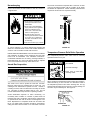
IMPORTANT: The water heater should be located in an area
where leakage of the tank or connections will not result in damage
to the area adjacent to the water heater or to lower floors of the
structure. Due to the normal corrosive action of water, the tank will
eventually leak after an extended period of time. Also any external
plumbing leak, including those from improper installation, may
cause early failure of the tank due to corrosion if not repaired. If
the homeowner is uncomfortable with making the repair a qualified
technician should be contacted. A suitable metal drain pan should
be installed under the water heater as shown below, to help protect
the property from damage which may occur from condensate
formation or leaks in the piping connections or tank. The pan
must limit the water level to a maximum depth of 1-3/4” and be
two inches wider than the heater and piped to an adequate drain.
NOTE: The pan must not restrict combustion air flow. Locate
the water heater near an adequate drain (Figure 1). In cold
climates, it is recommended that the drain pipe be terminated at
an adequate drain inside the building. The piping should be at
least 3/4” ID and pitched for proper drainage.
METAL
DRAIN
PAN
AT LEAST 2” GREATER THAN THE
DIAMETER OF THE WATER HEATER.
PIPED TO AN
ADEQUATE DRAIN
SEE FIGURE 1
FIGURE 8.
Water heater life depends upon water quality, water usage,
water temperature and the environment in which the water
heater is installed. Water heaters are sometimes installed in
locations where leakage may result in property damage, even
with the use of a metal drain pan piped to a drain. However,
unanticipated damage can be reduced or prevented by a leak
detector or water shut-off device used in conjunction with a
piped metal drain pan. These devices are available from some
plumbing supply wholesalers and retailers, and detect and react
to leakage in various ways:
• Sensors mounted in the metal drain pan that trigger an
alarm or turn off the incoming water to the water heater
when water is detected.
• Sensors mounted in the metal drain pan that turn off the
water supply to the entire home when water is detected in
the drain pan.
• Water supply shut-off devices that activate based on the
water pressure differential between the cold water and hot
water pipes connected to the water heater.
• Devices that will turn off the gas supply to a gas water
heater while at the same time shutting off its water supply.
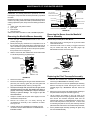
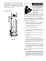
Securing Water Heater to Floor and Wall
The water heater must be secured to the floor and to the wall
of the enclosure as described below. See also “Enclosure
Installation.”
1. After properly locating the water heater, fasten it to the
floor with the brackets and screws that were provided
(Figure 9). Simply pre-drill each screw location in the
metal drain pan and water heater jacket with a 1/8” drill bit.
Because of installation variances, these brackets can be
located at any points around the circumference of the jacket.
However, they should be spaced apart at equal distances.
CAUTION: When making pilot holes in the water
heater itself, ensure that you drill only the outer jacket.
Also, to prevent leaks in the metal drain pan, seal each drill
location with a heavy bead of silicone sealant.
2. Secure the top of the water heater with the provided bracket
and screws or install other acceptable means of support
(e.g., support strap).
SCREW
SCREW
BRACKET
BOTTOM OF WATER HEATER
FIGURE 9.
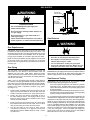
Insulation Blankets
Insulation blankets available to the general public for external
use on gas water heaters are not necessary with Kenmore
products. The purpose of an insulation blanket is to reduce the
standby heat loss encountered with storage tank heaters. Your
Kenmore water heater meets or exceeds the National Appliance
Energy Conservation Act standards with respect to insulation
and standby loss requirements, making an insulation blanket
unnecessary.
WARNING
Should you choose to apply an insulation blanket to this
heater, you should follow these instructions. (See Figure 1
for identification of components mentioned below). Failure to
follow these instructions can restrict the air flow required for
proper combustion, potentially resulting in fire, asphyxiation,
serious personal injury or death.
• Do not apply insulation to the top of the water heater, as
this will interfere with safe operation of the draft hood.
• Do not cover the outer door, thermostat or temperature &
pressure relief valve.
• Do not allow insulation to come within 2” (50.8 mm) of
the floor to prevent blockage of combustion air flow to the
burner.
• Do not cover the instruction manual. Keep it on the side of
the water heater or nearby for future reference.
• Do obtain new warning and instruction labels from Sears
for placement on the blanket directly over the existing
labels.

15
• Do inspect the insulation blanket frequently to make
certain it does not sag, thereby obstructing combustion air
flow.
Clearances and Accessibility
NOTE: Minimum clearances from combustible surfaces are
stated on the label adjacent to the gas control valve/thermostat
of the water heater. The water heater is certified for installation
on a combustible floor.
• IMPORTANT: If installing over carpeting, the carpeting
must be protected by a metal or wood panel beneath the
water heater. The protective panel must extend beyond the
full width and depth of the water heater by at least three
inches (76.2mm) in any direction; or if in an alcove or closet
installation, the entire floor must be covered by the panel.
• Figure 10 may be used as a reference guide to locate the
specific clearance locations. A minimum of 24 inches of
front clearance should be provided for inspection and
service.
BACK
SIDES
TOP
VIEW
SIDES
VENT
FRONT
24” MINIMUM
FOR SERVICE
TOP
TO
CEILING
FIGURE 10.
Filling the Water Heater
Never use this water heater unless it is completely full of water.
To prevent damage to the tank, the tank must be fi lled with water.
Water must fl ow from the hot water faucet before turning “ON” gas
to the water heater. To fi ll the water heater with water:
• Close the water heater drain valve by turning the handle to
the right (clockwise). The drain valve is on the lower front of
the water heater.
• Open the cold water supply valve to the water heater.
NOTE: The cold water supply valve must be left open
when the water heater is in use.
• To ensure complete fi lling of the tank, allow air to exit by
opening the nearest hot water faucet. Allow water to run until
a constant fl ow is obtained. This will let air out of the water
heater and the piping.
• Check all water piping and connections for leaks. Repair as
needed.

16
GAS CONVERSION
For your safety, the following procedures should be
performed by a qualified technician as it involves
disconnection of gas piping and leak testing.
WARNING
Do not connect a natural gas water heater to an L.P.
gas supply.
Do not connect an L.P. gas water heater to a natural
gas supply.
t
t
t
FIGURE 12.FIGURE 11.
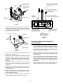
A. Remove the Manifold/Burner Assembly
1. Turn off the gas supply to the water heater at the manual
gas shut-off valve. This valve is typically located beside the
water heater. Note the position of the shut-off valve in the
open/on position, then proceed to turn it off.
2. On the lower front of the water heater, locate the gas control
valve/thermostat.
3. Turn the gas control/temperature knob to the “OFF” position.
With the unit shut-off, allow sufficient time for the water
heater to cool before performing any maintenance.
4. Remove the outer door.
5. Remove the two screws securing the installed manifold
door assembly to the combustion chamber (Figure 11).
6. Disconnect the following from the gas control valve/thermostat:
pilot tube, igniter wire, and manifold tube. See Figure 11.
7. Using needle nose pliers, disconnect the white and red
thermopile wires from the gas control valve/thermostat
(Figure 11).
8. Grasp the manifold tube and push down slightly to free the
manifold tube and pilot tube.
9. Carefully remove the manifold/burner assembly from the burner
compartment. NOTE: Be sure not to damage internal parts.
B. Convert the Gas Control Valve/Thermostat
1. Remove the cap (shown in Figure 12).
2. Remove the conversion fitting by turning it counter-clockwise
with a flathead screwdriver.
3. Thread the opposite end of the conversion fitting into the opening
by turning it clockwise, then tighten it with a flathead screwdriver.
a. LP GAS: If you are converting the unit to use LP gas
(propane), verify that “LP” is marked on the exposed end
of the fitting. “LP” must face outward (toward you.) See
Figure 12. If “NAT” faces outward, repeat step 2.
b. NATURAL GAS: If you are converting the unit to use
natural gas, verify that “NAT” is marked on the exposed
end of the fitting. “NAT” must face outward (toward you.)
See Figure 12. If “LP” faces outward, repeat step 2.
4. Replace the cap.
C. Install the Conversion Manifold/Burner
Assembly
1. Check the door gasket for damage or imbedded debris prior
to installation.
2. Inspect the view port for damage and replace as required.
3. Insert the conversion manifold/burner assembly into the
burner compartment, making sure that the tip of the manifold
tube engages in the slot of the bracket inside the combustion
chamber. NOTE: For 30 gallon models, the LP manifold/
burner assembly is identified by a yellow square (label) on
the packaging. For 40 gallon models, the LP manifold/burner
assembly is identified by a green square on the packaging.
4. Inspect the door gasket and make sure there is no fiberglass
insulation between the gasket and the combustion chamber.
5. Replace the two screws that secure the manifold/burner
assembly door to the combustion chamber, then tighten
them securely. There should be no space between the
gasket part of the manifold door and the combustion
chamber. IMPORTANT: Do not operate the water heater
if the door gasket does not create a seal between the
manifold door and the combustion chamber.
6. Reconnect the manifold tube and pilot tube to the gas
control valve/thermostat (Figure 11). Do not cross-thread
or apply any thread sealant to the fittings. IMPORTANT: If
you were supplied with a new ferrule nut in a parts kit, follow
these steps to connect the pilot tube:
A.) Install the ferrule nut into the gas valve at the pilot tube
location, hand tight only. B.) Insert the pilot tube into the
ferrule nut until the tube bottoms out, then tighten the nut with
a 7/16” wrench until the crimp connection seals to the pilot tube.
C.) Continue to tighten until the nut is tight in the gas valve.
7. Connect the white and red thermopile wires to the gas
control valve/thermostat. See Figure 11.
8. Reconnect the igniter wire.
9. Turn the gas supply on and follow the Lighting Instructions.
10. With the main burner lit, check for leaks at the manifold and
pilot connections by brushing on an approved non-corrosive
leak detection solution. If such a solution is not available,
use a mixture of hand dish washing soap and water (one
part soap to 15 parts water). Bubbles forming indicate a
leak. Correct any leak found.
11. Verify proper operation; replace outer door.
VAC
MANIFOLD SCREW (2)
MANIFOLD COMPONENT BLOCK
MANIFOLD
DOOR
THERMAL
SWITCH
PILOT TUBE
MANIFOLD TUBE
VIEWPORT
THERMOPILE
WIRE
CONNECTIONS
PIEZO IGNITER BUTTON
GAS CONTROL/
TEMPERATURE KNOB
OUTER DOOR
NOT SHOWN
GAS CONTROL VALVE/THERMOSTAT CONNECTIONS
IGNITER
WIRE
RED WIRE
(LEFT SIDE)
PILOT
T
UBE MANIFOLD TUBE
IGNITER
BUTTON
IGNITER
LEAD
WIRE
WHITE
WIRE
(RIGHT
SIDE)
GAS CONTROL VALVE/THERMOSTAT
CONVERSION FITTING
CAP
NATURAL GAS:
“NAT” FACES OUTWARD
(TOWARD YOU).*
LP GAS:
“LP” FACES OUTWARD
(TOWARD YOU).*
* ORIENTATION MAY VARY. FITTING TO BE TIGHT.

17
Explosion Hazard
• Use a new CSA approved gas supply line.
• Install a shut-off valve.
• Do not connect a natural gas water heater to an
L.P. gas supply.
• Do not connect an L.P. gas water heater to a
natural gas supply.
• Failure to follow these instructions can result in
death, explosion, or carbon monoxide poisoning.
WARNING
Gas Requirements
IMPORTANT: Read the rating plate to be sure the water heater
is made for the type of gas you will be using in your home. This
information will be found on the rating plate located near the gas
control valve/thermostat. If the information does not agree with
the type of gas available, do not install or light. Call your dealer.
NOTE: An odorant is added by the gas supplier to the gas used
by this water heater. This odorant may fade over an extended
period of time. Do not depend upon this odorant as an indication
of leaking gas.
Gas Piping
The gas piping must be installed according to all local and
state codes or, in the absence of local and state codes, the
“National Fuel Gas Code”, ANSI Z223.1 (NFPA 54)-current
edition. Manufactured home manufacturers must conform with
“The Manufactured Home Construction and Safety Standard,
Title 24 CFR, Part 3280”.
Tables 1 and 2 on the following page provide a sizing reference
for commonly used gas pipe materials. Consult the “National Fuel
Gas Code” for the recommended gas pipe size of other materials.
NOTE: Use pipe joint compound or teflon tape marked as being
resistant to the action of petroleum [Propane (L.P.)] gases.
(See Figure 13.)
1. Install a readily accessible manual shut-off valve in the gas
supply line as recommended by the local utility. Know the
location of this valve and how to turn off the gas to this unit.
2. Install a drip leg (if not already incorporated as part of
the water heater) as shown. The drip leg must be no less
than three inches long for the accumulation of dirt, foreign
material, and water droplets.
3. Install a ground joint union between the gas control valve/
thermostat and the manual shut-off valve. This is to allow
easy removal of the gas control valve/ thermostat.
4. Turn the gas supply on and check for leaks. Test all
connections by brushing on an approved noncorrosive
leak-detection solution. Bubbles will show a leak. Correct
any leak found.
CHECK WITH
LOCAL UTILITY
FOR MINIMUM HEIGHT
3” MINIMUM
DRIP LEG
GROUND
JOINT
UNION
MANUAL GAS
SHUT-OFF VALVE
FIGURE 13.
Gas Pressure
WARNING
Explosion Hazard
• Gas leaks can not always be detected by smell.
• Gas suppliers recommend that you use a gas
detector approved by UL or CSA.
• For more information, contact your gas supplier.
• If a gas leak is detected, follow the “What to do if you
smell gas” instructions on the cover of this manual.
IMPORTANT: The gas supply pressure must not exceed the maximum
supply pressure as stated on the water heater’s rating plate. The
minimum supply pressure is for the purpose of input adjustment.
Gas Pressure Testing
IMPORTANT: This water heater and its gas connection must be
leak tested before placing the appliance in operation.
• If the code requires the gas lines to be tested at a pressure
exceeding 14” W.C., the water heater and its manual shut-off
valve must be disconnected from the gas supply piping system
and the line capped.
• If the gas lines are to be tested at a pressure less than 14” W.C.,
the water heater must be isolated from the gas supply piping
system by closing its manual shut-off valve.
U.L. recognized fuel gas and carbon monoxide (CO) detectors are
recommended in all applications and should be installed using the
manufacturer’s instructions and local codes, rules and regulations.
NOTE: Air may be present in the gas lines and could prevent the
pilot from lighting on initial start-up. The gas lines should be purged
of air by a qualified technician after installation of the gas piping
system. While purging the gas piping system of air, ensure that
the fuel is not spilled in the area of the water heater installation,
or any source of ignition. If the fuel is spilled while purging the
piping system of air follow the “WHAT TO DO IF YOU SMELL
GAS” instructions on the cover of this manual.
GAS SUPPLY

18
LP Gas Only
Liquefi ed petroleum gas is over 50% heavier than air and in the
occurrence of a leak in the system, the gas will settle at fl oor level.
Basements, crawl spaces, skirted areas under mobile homes
(even when ventilated), closets and areas below ground level will
serve as pockets for the accumulation of gas. Before lighting an
L.P. gas water heater, smell all around the appliance at fl oor level.
If you smell gas, follow the instructions as given in the warning on
the front page.
When your L.P. tank runs out of fuel, turn off the gas at all gas
appliances including pilot lights. After the tank is refi lled, all
appliances must be re-lit according to their manufacturer’s
instructions.
WARNING
Explosion Hazard
Have a qualified technician make sure that the L.P.
gas operating pressure does not exceed 13” water
column.
Failure to do so can result in death, explosion, or fire.

19
Carbon Monoxide Warning
The vent system must be installed according to all
local and state codes or, in the absence of local and
state codes, the “National Fuel Gas Code”, ANSI
Z223.1 (NFPA 54)-current edition. Manufactured home
manufacturers must comply with the “Manufactured
Home Construction and Safety Standard, Title 24 CFR,
Part 3280.”
Failure to do so can result in death, explosion, or
carbon monoxide poisoning.
WARNING
IMPORTANT: Air for combustion and ventilation must not come
from a corrosive atmosphere. Any failure due to corrosive elements
in the atmosphere is excluded from warranty coverage.
The following types of installation (not limited to the following)
will require outdoor air for combustion due to chemical exposure
and may reduce but not eliminate the presence of corrosive
chemicals in the air:
• beauty shops
• photo processing labs
• buildings with indoor pools
• water heaters installed in laundry, hobby, or craft rooms
• water heaters installed near chemical storage areas
Combustion air must be free of acid-forming chemicals such as sulfur,
fluorine, and chlorine. These elements are found in aerosol sprays,
detergents, bleaches, cleaning solvents, air fresheners, paint, and
varnish removers, refrigerants, and many other commercial and
household products. When burned, vapors from these products
form highly corrosive acid compounds. These products should not
be stored or used near the water heater or air inlet.
Vent Pipe System
This water heater uses a non-direct, single-pipe vent system
to remove exhaust gases created by the burning of fossil
fuels. Air for combustion is taken from the immediate water
heater location or is ducted in from the outside (see “Enclosure
Installation”).
This water heater must be properly vented for the removal of
exhaust gases to the outside atmosphere. Correct installation
of the vent pipe system is mandatory for the proper and efficient
operation of this water heater and is an important factor in the
life of the unit.
The vent pipe must be installed according to all local and state
codes or, in the absence of local and state codes, the “National
Fuel Gas Code”, ANSI Z223.1 (NFPA 54)-current edition.
Manufactured home manufacturers must conform with “The
Manufactured Home Construction and Safety Standard, Title
24 CFR, Part 3280.” The vent pipe installation must not be
obstructed so as to prevent the removal of exhaust gases to the
outside atmosphere.
IMPORTANT: The use of vent dampers is not recommended
by the manufacturer of this water heater. Although some vent
dampers are certified by CSA International, this certification
applies to the vent damper device only and does not mean they
are certified for use on this water heater.
COMBUSTION AIR SUPPLY & VENTILATION
U.L. recognized fuel gas and carbon monoxide (CO) detectors are
recommended in all applications and should be installed using the
manufacturer’s instructions and local codes, rules, or regulations.
IMPORTANT:
• If you lack the necessary skills required to properly install
this venting system, you should not proceed, but get help
from a qualified technician.
• DO NOT common vent this water heater with any other
appliance.
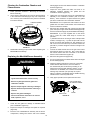
Draft Hood Installation
SHEET METAL SCREWS (FOUR PROVIDED)
DRAFT HOOD
LEGS
LEGS
SLOT
SLOT
JACKET TOP
INSTALL THE DRAFT HOOD WITH
THE FOUR SCREWS PROVIDED.
FIGURE 14.
Align the legs of the draft hood with the slots provided. Insert
the legs and secure the draft hood to the water heater’s top
with the four screws provided as shown in Figure 14. Do not
alter the draft hood in any way. If you are replacing an existing
water heater, be sure to use the draft hood supplied with this
water heater.
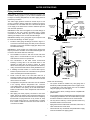
Roof Jack Installation
This water heater must have a properly-installed draft hood
and be connected to a listed roof jack that terminates to the
outdoors. The roof jack vent pipe must be secured to the draft
hood with sheet metal screws. (Roof jack not furnished.)
The following roof jack models are certified for use with this
water heater:
1. Field Controls No. 987
2. Ventline 2073
3. White Metal Products 3RJ
Install the roof jack according to its manufacturer’s instructions.

20
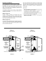
Enclosure Installation
Air for combustion and ventilation must not be supplied from
the occupied spaces of the manufactured (mobile) home.
IMPORTANT: The opening that provides outside air to your
water heater must have a minimum free area of 20 square
inches. Also, ensure that your installation complies with all
applicable code requirements.
The following methods may be used to provide sufficient
combustion and ventilation air to the water heater when it is
installed in the enclosure.
Method I (Figure 15)
Provide a single air opening in the exterior door of the
enclosure. The opening must have a minimum free area of
20 square inches. The bottom of the opening must be within
6 inches from the bottom edge of the door. Cover the opening
with 1/4 inch wire mesh screen or louvers.
Method II (Figure 16)
For enclosures with a solid exterior door, provide an air opening
in the floor. The opening must have a minimum diameter of 5
inches (20 square inches minimum free area) and be covered
with 1/4-inch wire mesh screen.
ROOF JACK
(NOT INCLUDED)
ROOF
CEILING
SECURE TOP
TO WALL WITH
STRAP AND
SCREWS
MAINTAIN MIN.
CLEARANCES
FLOOR
OUTSIDE
FRESH
AIR
ONE OPENING
IN DOOR *
PROTECTION:
1/4 IN. WIRE
MESH OR
LOUVERS
METAL
DRAIN PAN
SECURE WATER HEATER
TO FLOOR WITH BRACKETS
AND SHEET METAL
SCREWS (PROVIDED)
MAINTAIN MIN.
CLEARANCE PER CODE
6 INCHES MAX.
ABOVE BOTTOM
EDGE OF DOOR
MAINTAIN MIN. CEILING
CLEARANCE PER LABEL
ON WATER HEATER
* FREE AREA FOR AIR OPENING: 20 SQ. IN. MIN.
OPENING:
20 SQ. IN. MIN.
FIGURE 15.
Also, if the manufactured home is skirted, an air intake opening
with a minimum free area of 32 square inches must be provided
in the skirt. Other gas fired appliances in the home may require
additional free air openings. Consult the manufacturers for
correct sizing.
IMPORTANT:
• When using Method II, ensure that the drain pan does not
cover the air intake opening in the floor.
• A discharge line must be installed as described in the
“Temperature and Pressure Relief Valve” section.
• Do not obstruct the combustion and ventilation air openings.
• Do not use the enclosure as a storage area.
• Secure the water heater as described in “Securing Water
Heater to Floor and Wall.”
ROOF JACK
(NOT INCLUDED)
ROOF
CEILING
SECURE TOP
TO WALL WITH
STRAP AND
SCREWS
MAINTAIN MIN.
CLEARANCES
FLOOR
METAL
DRAIN PAN
FLOOR OPENING (5 IN. MIN. DIA.) *
1/4 IN. WIRE MESH PROTECTION
IMPORTANT: DRAIN PAN MUST
NOT BLOCK OR COVER AIR INTAKE
AIR INTAKE
SECURE WATER HEATER
TO FLOOR WITH BRACKETS
AND SHEET METAL
SCREWS (PROVIDED)
MAINTAIN MIN.
CLEARANCE PER CODE
MAINTAIN MIN. CEILING
CLEARANCE PER LABEL
ON WATER HEATER
* FREE AREA FOR AIR OPENING: 20 SQ. IN. MIN.
Method I:
Door Opening
Method II:
Floor Opening
FIGURE 16.
Page is loading ...
Page is loading ...
Page is loading ...
Page is loading ...
Page is loading ...
Page is loading ...
Page is loading ...
Page is loading ...
Page is loading ...
Page is loading ...
Page is loading ...
Page is loading ...
Page is loading ...
Page is loading ...
Page is loading ...
Page is loading ...
Page is loading ...
Page is loading ...
Page is loading ...
Page is loading ...
Page is loading ...
Page is loading ...
Page is loading ...
Page is loading ...
-
 1
1
-
 2
2
-
 3
3
-
 4
4
-
 5
5
-
 6
6
-
 7
7
-
 8
8
-
 9
9
-
 10
10
-
 11
11
-
 12
12
-
 13
13
-
 14
14
-
 15
15
-
 16
16
-
 17
17
-
 18
18
-
 19
19
-
 20
20
-
 21
21
-
 22
22
-
 23
23
-
 24
24
-
 25
25
-
 26
26
-
 27
27
-
 28
28
-
 29
29
-
 30
30
-
 31
31
-
 32
32
-
 33
33
-
 34
34
-
 35
35
-
 36
36
-
 37
37
-
 38
38
-
 39
39
-
 40
40
-
 41
41
-
 42
42
-
 43
43
-
 44
44


Kenmore 30 gal. Mobile Home Natural Gas Water Heater Installation guide
- Category
- Water heaters & boilers
- Type
- Installation guide
- This manual is also suitable for
Ask a question and I''ll find the answer in the document
Finding information in a document is now easier with AI
Related papers
-
Kenmore 153.332.410 User manual
-
-
-
-
Kenmore POWER MISER 9 153.339572 User manual
-
-
-
-
-
Other documents
-
Rheem PROG50-40N RH67 PDV User guide
-
State 186489-002 User manual
-
State Water Heaters GSX Series Installation Instructions And Use & Care Manual
-
State GCFL series User manual
-
-
 AO Smith GVR Series User manual
-
-
Lochinvar RESIDENTIAL GAS WATER HEATERS Use and Care Manual with Installation Instructions
-
-
Reliance 6 40 NOMT Installation guide
