Crown Audio CTs Series User manual
- Category
- Audio amplifiers
- Type
- User manual

CTs SERIES
B
uilding on the foundation of the Com-Tech
®
Series, Crown’s CTs Series offers new fl ex-
ibility and value for installed sound applica-
tions. The Com-Tech Series were the fi rst to offer
independent selection of high- and low-impedance
operation for a specifi c channel, and CTs Series
amplifi ers continue that tradition, with power
levels and features carefully chosen to perfectly
integrate into fi xed install design requirements.
For added fl exibility, the CTs Series includes both
dual-channel and multi-channel models.
All models in the CTs Series feature Crown’s new
Switching Power Supply for lighter weight, and all
models are also compatible with the IQ System
®
.
Multi-channel models accept new MC accessory
modules that provide enhanced control, monitor-
ing, and system integration.
The CTs multi-channel amps feature FIT (Fault Iso-
lation Topology), which isolates channel-specifi c
faults and prevents them from affecting remaining
channels. If a CTs multi-channel amp is powering
multiple zones, and a channel fails, the other zones
continue to operate.
In a profession where unplanned service calls
quickly wipe out profi ts, the CTs Series amplifi ers
are designed to be the most reliable amplifi ers you
can install.
For more details about the Crown
®
CTs Series,
contact Crown Customer Service at 800-342-6939
or 574-294-8200. Also, visit the Crown Audio web-
site at www.crownaudio.com.
Specifi cations
Minimum Guaranteed Power: See power charts
below.
Frequency Response (at 1 watt, 20 Hz - 20 kHz):
±0.5 dB.
Phase Response (at 1 watt, 10 Hz - 20 kHz): ±35°.
Signal to Noise Ratio below rated power (20 Hz to
20 kHz): 100 dB unweighted.
Total Harmonic Distortion (THD) at 1 watt, from
20 Hz to 20 kHz: < 0.05%.
Intermodulation Distortion (IMD) 60 Hz and 7
kHz at 4:1, from 163 milliwatts to full bandwidth
power: < 0.05% (typical).
Damping Factor: 10 Hz to 400 Hz: >180.
Crosstalk (below rated power, 20 Hz to 1 kHz):
> 80 dB.
Common Mode Rejection (CMR) (20 Hz to 1 kHz):
> 50 dB.
DC Output Offset (Shorted input): < ±5 mV.
Input Impedance (nominal): 20 kilohms balanced,
10 kilohms unbalanced.
Maximum Input Level (before input compres-
sion): + 20 dBu.
Load Impedance (Note: Safe with all types of
loads):
Stereo: 4/8 and 25 ohms (70V)
Bridge Mono: 8/16 and 50 ohms (100V)
Voltage Gain (at maximum level setting), 1.4V
sensitivity,
4/8 Ohm Operation: 20:1 (26 dB);
70V Operation: 50:1 (34 dB)
100V Operation: 71.4:1 (37 dB)
Required AC Mains: 120V 60 Hz, 220/230/
240V/50 Hz.
Power Draw at Idle (120VAC mains, all channels
in 4/8 ohm mode): 58W.
Power Draw at Idle (120VAC mains, all channels
in 70V mode): 77W.
Cooling: Continuously variable speed forced air,
front-to-back airfl ow.
Dimensions (Width, Height, Depth):
CTs 4200: 19 in. (48.3 cm) W x 3.5 in. (8.9 cm)
H x 16.25 in. (41.3 cm) D.
CTs 8200: 19 in. (48.3 cm) W x 5.25 in. (13.3
cm) H x 16.25 in. (41.3 cm) D.
Features
• New Crown Switching Power Supply for
reduced weight.
• High power-density, with four channels (CTs
4200) or eight channels (CTs 8200) in a 3U
chassis.
• Selectable constant-voltage (70V/100V) or
low-impedance (4/8 ohm) operation for each
channel pair. (Channel pair must be operated
in Bridge mode for 100V output).
• FIT (Fault Isolation Topology) circuitry isolates
faults within affected channels.
• TLC protection circuitry protects the amplifi er
from excessive heat by subtly and dynamically
reducing the gain only when necessary to
reduce heat levels.
• Accepts new MC accessory modules that tailor
the amplifi er to suit specifi c applications. Mod-
ules available for remote VCA level control and
IQ System
®
Control.
• 35-Hz High-Pass Filter is automatically
inserted when the channel pair is set for con-
stant-voltage operation (corner frequency may
be changed as a service option).
• Comprehensive array of indicators including
Power and Data, along with Bridge, Ready,
Signal, Clip, Thermal and Fault for each chan-
nel, provide accurate diagnostics.
• Blue Power Indicator fl ashes if the amplifi er
shuts off due to an under/over voltage condition
on the AC mains.
• Advanced protection circuitry guards against:
shorted outputs, open circuits, DC, mismatched
loads, general overheating, under-/over-volt-
age, high-frequency overloads and internal
faults.
• Proven Crown AB+B Multi-Mode
®
output topol-
ogy.
• Continuously-variable fans optimize cooling effi -
ciency.
• Three Year, No-Fault, Fully Transferable
Warranty completely protects your investment
and guarantees its specifi cations.
• Crown’s advance-replacement Profi t Protec-
tion Plan provides quick, no-questions-asked
replacement of covered amps should they fail
at any time up to 6 months following date of
installation.
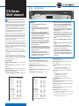
CTs Series
Multi-channel
4-ohm (per ch.)
8-ohm (per ch.)
70V (per ch.)
1 kHz
CTs 4200
20 Hz–20 kHz
Dual
4 Channels Driven
260W
180W
220W
215W
190W
220W
*
*
4-ohm (per ch.)
8-ohm (per ch.)
70V (per ch.)
1 kHz 20 Hz–20 kHz1 Channel Driven
270W
220W
250W
225W
210W
245W
8-ohm (per ch. pair)
16-ohm (per ch. pair)
100V (per ch. pair)
1 kHz 20 Hz–20 kHz
Bridge-Mono
2 Channel-Pairs Driven
520W
400W
220W
430W
380W
220W
*
*
8-ohm (per ch. pair)
16-ohm (per ch. pair)
100V (per ch. pair)
1 kHz 20 Hz–20 kHz1 Channel-Pair Driven
560W
440W
250W
450W
420W
245W
Maximum Average Power
in watts with 0.1% THD.
*
Constant Voltage full bandwidth power ratings support
100Hz - 20kHz due to automatic High-Pass Filters.
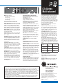
4-ohm (per ch.)
8-ohm (per ch.)
70V (per ch.)
1 kHz
CTs 8200
20 Hz–20 kHz
Dual
8 Channels Driven
200W
160W
200W
175W
155W
185W
*
*
4-ohm (per ch.)
8-ohm (per ch.)
70V (per ch.)
1 kHz 20 Hz–20 kHz1 Channel Driven
270W
220W
250W
230W
220W
230W
8-ohm (per ch. pair)
16-ohm (per ch. pair)
100V (per ch. pair)
1 kHz 20 Hz–20 kHz
Bridge-Mono
4 Channel-Pairs Driven
400W
320W
200W
350W
310W
185W
*
*
8-ohm (per ch. pair)
16-ohm (per ch. pair)
100V (per ch. pair)
1 kHz 20 Hz–20 kHz1 Channel-Pair Driven
540W
440W
250W
460W
440W
230W
Maximum Average Power
in watts with 0.1% THD.
*
Constant Voltage full bandwidth power ratings support
100Hz - 20kHz due to automatic High-Pass Filters.

Crown International
1718 W. Mishawaka Rd.
Elkhart, IN 46517-9439
TEL: 574-294-8200
FAX: 574-294-8FAX
www.crownaudio.com
4/05 136318-1F
CTs Series
Multi-channel
Weight (Net, Shipping):
CTs 4200: 27 lb 8 oz (12.5 kg),
32 lb (14.5 kg)
CTs 8200: 36 lb 6 oz (16.5 kg),
47 lb (21.3 kg).
Front Panel Controls and Indicators
Bridge Mode Indicator: Yellow LED, one per chan-
nel pair, illuminates when the channel pair’s Mode
Switch is set to the “Bridge” position. If Mode
switch is changed while amplifi er is powered up,
Bridge LED will fl ash, indicating that the amplifi er
must be powered off and on to reset the Mode.
Ready Indicator: Green LED, one per channel, illu-
minates when the channel is initialized and ready
to produce audio output.
Signal Indicator: Green LED, one per channel, illu-
minates to indicate the presence of input signals
above –40 dBu.
Clip Indicator: Red LED, one per channel, illumi-
nates when the THD of the channel’s output signal
rises to a level typically considered as the onset
of audible clipping. The Clip Indicator also will
illuminate during Thermal Level Control (TLC) or
input overload.
Thermal Indicator: Red LED, one per channel,
fl ashes when a state of thermal stress or overload
has caused the channel to shut down. If the power
supply goes into thermal overload, all channel
LEDs will fl ash.
Fault Indicator: Red LED, one per channel, fl ashes
when a fault condition has occurred in the channel.
Ventilation Grille: Front-to-rear forced airfl ow.
Data Indicator: Yellow LED indicates IQ Loop data
activity (if the amplifi er is equipped with an IQ-MC
module, and connected to an IQ Loop).
Power Indicator: Blue LED indicates amplifi er has
been turned on and AC power is available. Indica-
tor also fl ashes if the amplifi er shuts off due to an
under-/over-voltage condition on the AC mains.
Power Switch: Amplifi er is on when the switch is
in the IN position.
Back Panel Controls and Connectors
AC Power Cord Connector: IEC inlet, type 320;
100/120VAC units: 15A;
220/230/240VAC units: 10A.
Voltage is indicated above IEC inlet.
Output Connectors: One four-pole terminal strip
for every two channels with touch-proof cover.
Accepts up to 10 AWG terminal forks.
Accessory Panel: CTs 4200 accepts an optional
IQ-MC4A or VCA-MC4A module. CTs 8200 accepts
an optional IQ-MC8 or VCA-MC8 module.
Channel Level Controls: One 21-position detented
rotary potentiometer per channel, ranging from
infi nity (–70 dB) to 0 dB attenuation.
Input Connectors: Removable Phoenix-style bar-
rier connectors for balanced input.
Mode Switch: Used on each consecutive pair
of channels, this four-position switch is used to
select the amplifi er’s mode of operation: Dual 8/4
ohms, Dual 70V, Bridge-Mono 16/8 ohms, and
Bridge-Mono 100V.
Cooling Vents: Front-to-rear forced airfl ow.
Options
Control Modules: IQ-MC4A: IQ module for CTs
4200A; VCA-MC4A: VCA module for CTs 4200A.
IQ-MC8: IQ module for CTs 8200; VCA-MC8: VCA
module for CTs 8200.
Wall-mount level control panels for use with VCA
module: 1-VCAP: Single-gang panel with 1 VCA
channel volume control; 4-VCAP: Two-gang panel
with 4 VCA channel volume controls.
T-170V: This is an autoformer that allows 100V
output from the amplifi er, and allows other ampli-
fi ers without direct constant voltage output to be
easily integrated into distributed systems.
TP-170V: This is a rack-mountable panel with four
autoformers as described above.
Protection Systems
Thermal Level Control (TLC): If an amplifi er chan-
nel starts to overheat, the TLC circuit will engage
that channel’s input compressor. By compress-
ing the input, the amplifi er will not generate as
much heat and will have a chance to cool down.
The degree of compression is proportional to the
amount of overheating. If the channel becomes
too hot for safe operation even after full TLC
limiting, the channel will shut off, and the Thermal
Indicator for that channel will fl ash brightly to alert
the user that a state of thermal stress or overload
has cause the channel to shut down.
FIT (Fault Isolation Topology): Isolates faults
within affected channels.
Fault: If an amplifi er channel requires service,
the corresponding Fault indicator will illuminate
to alert the user of this condition. If this occurs,
return the amplifi er to the Crown factory or to an
authorized Crown service center.
35-Hz High-Pass Filter: A fi xed 35-Hz high-pass
fi lter per channel pair is automatically inserted
when the mode switch is set to either of the con-
stant-voltage settings. The high-pass fi lter corner
frequency can be set to 70 Hz, or bypassed, with
a service option.
AC Under-/Over-Voltage Protection: If the AC
line voltage varies out of an acceptable range, the
amplifi er’s power supply turns off and the blue
Power LED fl ashes. The amplifi er will turn back on
when the AC line voltage returns to safe operating
levels.
Models
Under-Voltage
Limit
Over-Voltage
Limit
100VAC (CTs
8200 only)
90VAC 110VAC
120 VAC units 108VAC 132VAC
220V/230V/240V
units
198VAC 264VAC
Power Fuse: A fuse protects the amplifi er from
excessive AC current draw.
Inrush Limiting: A soft-start circuit in the power
supply minimizes the amplifi er’s current draw
during power-on.
Variable-speed Fan: Continuously variable speed
fan directs the airfl ow through the amplifi er for
cooling.
Specifi cations subject to change without prior notice. Latest
information available at www.crownaudio.com.
Crown, Crown Audio, IQ System and Multi-Mode are
registered trademarks of Crown International. Other trade-
marks are the property of their respective owners.
Printed in U.S.A.
© 2005 Crown Audio
®
, Inc.
Crown’s Three-Year, No-Fault, Fully Transferable Warranty
Crown offers a Three-Year, No-Fault, Fully Transferable Warranty for every new Crown amplifi er—an
unsurpassed industry standard. With this unprecedented No-Fault protection, your new Crown
amplifi er is warranted to meet or exceed original specifi cations for the fi rst three years of ownership.
During this time, if your amplifi er fails, or does not perform to original specifi cations, it will be
repaired or replaced at our expense. About the only things not covered by this warranty are those
losses normally covered by insurance and those caused by intentional abuse. And the coverage is
transferable, should you sell your amplifi er.
See your authorized Crown dealer for full warranty disclosure and details. For customers outside
of the USA, please contact your authorized Crown distributor for warranty information or call
574-294-8200.
-
 1
1
-
 2
2


Crown Audio CTs Series User manual
- Category
- Audio amplifiers
- Type
- User manual
Ask a question and I''ll find the answer in the document
Finding information in a document is now easier with AI
Related papers
-
 Crown Audio CTs 8200 User manual
-
 Crown Audio TP-170V User manual
-
Crown Audio CTs 4200 User manual
-
 Crown Audio XLS-802 User manual
-
 Crown Audio XLS-602 A User manual
-
 Crown Audio K2 User manual
-
 Crown Audio CTs 4200 USP/CN User manual
-
 Crown Audio 2X1100 User manual
-
 Crown Audio CDi 1000 User manual
-
Crown Audio CDi 2000 User manual


