
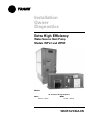
WSHP-SVX04A-EN
Models
“A” and later Design Sequence
Installation
Owner
Diagnostics
Extra High Efficiency
Water-Source Heat Pump
Models WPVJ and WPHF
WPVJ
018-072
– 60 HZ
WPHF
021-057 – 60 HZ

© 2003 American Standard Inc. All rights reserved. WSHP-SVX04A-EN
Notice
NOTICE:
Warnings and Cautions appear at appropriate sections throughout this manual.
Read these carefully.
WARNING -Indicates a potentially hazardous situation which, if
not avoided, could result in death or serious injury.
CAUTION -Indicates a potentially hazardous situation which, if not
avoided, may result in minor or moderate injury. It
may also be used to alert against unsafe practices.
CAUTION -Indicates a situation that may result in equipment or
property-damage-only accidents.
NOTICE:
Unit contains HCFC (R-22) Refrigerant
Instructions!
Section 608, Paragraph C of the 1990 Clean Air Act states:
Effective July 1, 1992, it shall be unlawful for any person, in course of
maintaining, servicing, repairing, or disposing of an air conditioning system, to
knowingly vent or release any CFC or HCFC refrigerant. Minimal releases (air
purges or refrigerant hoses) associated with good faith attempts to recapture or
recycle are exempt from the ban on venting.
Responsible Refrigerant Practices!
Trane believes that responsible refrigerant practices are important to the
environment, our customers, and the air conditioning industry. All technicians
who handle refrigerants must be certified. The Federal Clean Air Act (Section 608)
sets forth the requirements for handling, reclaiming, recovering and recycling of
certain refrigerants and the equipment that is used in these service procedures.
In addition, some states or municipalities may have additional requirements that
must also be adhered to for responsible management of refrigerants. Know the
applicable laws and follow them.
Important!
Equipment is shipped FOB (Free on
Board) at the manufacturer. Therefore,
freight claims for damages against the
carrier must be initiated by the receiver.

WSHP-SVX04A-EN 3
Contents
Installation/Startup/Commissioning
4
Pre-installation Checklist
4
General Information
5
Dimensions/Weights
6
Installation Instructions
14
Electrical Requirements
20
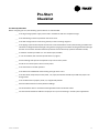
Pre-Startup Checklist
25
Startup/Commissioning
26
Sequence of Operation
26
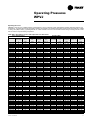
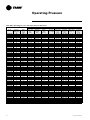
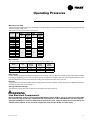
Operating Pressures
27
30
Startup Checklist & Log
30
Maintenance
31
Warranty Information
32
Troubleshooting Checklist
33
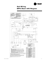
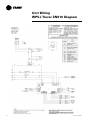
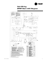
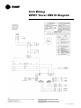
Unit Wiring
35

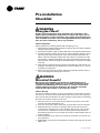
4 WSHP-SVX04A-EN
WARNING
Fiberglass Wool!
Product contains fiberglass wool. Disturbing the insulation in this
product during installation, maintenance or repair will expose you to
airborne particles of glass wool fibers and ceramic fibers known to the
state of California to cause cancer through inhalation. Glass wool fibers
may also cause respiratory, skin or eye irritation.
Jobsite Inspection
Always perform the following checks before accepting a unit:
1. Verify that the nameplate data matches the data on the sales order and bill of
lading (including electrical data).
2. Verify that the power supply complies with the unit nameplate specifications.
3. Visually inspect the exterior of the unit, for signs of shipping damage. Do not
sign the bill of lading accepting the unit(s) until inspection has been com-
pleted. Check for damage promptly after the unit(s) are unloaded. Once the
bill of lading is signed at the jobsite, the unit(s) are now the property of the
SOLD TO party and future freight claims MAY NOT be accepted by the freight
company.
4. Verify that the refrigerant charge has been retained during shipment by use
of gauges. Schrader taps are located external to the cabinet on the 1 1/2-ton
through 6-ton equipment.
5. After assuring that charge has been retained, reinstall the schrader caps to
assure that refrigerant leakage does not occur.
WARNING
Microbial Growth!
Wet interior unit insulation can become an amplification site for
microbial growth (mold), which may cause odors and damage to the
equipment and building materials. If there is evidence of microbial
growth (mold) on the interior insulation, the insulation should be
removed and replaced prior to operating the system.
Jobsite Storage
This unit is intended for indoor use only. To protect the unit from damage due to
the elements, and to prevent possible IAQ contaminant sources from growing,
the unit should be stored indoors. If indoor storage is not possible, the following
provisions for outdoor storage must be met:
1. Place the unit(s) on a dry surface or raise above the ground to assure ade-
quate air circulation beneath the unit.
2. Cover the unit(s) with a water proof tarp to protect them from the elements.
3. Make provisions for continuous venting of the covered units to prevent
moisture from standing on the unit(s) surfaces. Wet interior unit insulation
can become an amplification site for microbial growth (mold) which has
been determined to be a cause of odors and serious health related indoor air
quality problems.
4. Store refrigeration units units in the normal UP orientation to maintain oil in
the compressor.
5. Model WPHF units should not be stacked more than three high. Do not stack
WPVJ units.
Pre-installation
Checklist

WSHP-SVX04A-EN 5
General
Information
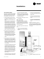
Unit Nameplate
The unit nameplate is located at the
front of the unit. It includes the unit
model number, serial number, electri-
cal characteristics, refrigerant charge,
and other pertinent unit data.
Compressor Nameplate
The nameplate for the compressors
are located on the compressor shell.
Unit Description
Before shipment, each unit is leak test-
ed, dehydrated, charged with refriger-
ant and run tested for proper control
operation.
Water-to-Refrigerant Coils
The co-axial water-to-refrigerant heat
exchanger for the 1 1/2-ton through 6-
ton equipment is constructed of cop-
per or cupro-nickel (option) for the wa-
ter section and stainless steel for the
refrigeration section.
The heat exchanger is leak tested to
assure there is no cross leakage be-
tween the water and refrigerant gas.
Water Connections
Water connections are located at the
unit front for both the WPVJ and
WPHF units. They are clearly labled for
supply/return connection. Sizes are as
follows.
Blower/Motor
The blower and motor is located inside
the unit cabinet. The motor may be
easily removed for service through the
equipment blower access panel.
Controls
The control system offered to control
the unit is a Basic 24 volt control, Basic
24 volt control, or Tracer
TM
ZN510
control. A 50 VA transformer is factory
supplied on the Basic 24V control con-
figurations. A 75 VA transformer is fac-
Dia. Type
3/4" WPHF 021-027 - Water in/out
1" WPHF 030-072 - Water in/out
1" WPVJ - Water in/out
3/4" Drain
1/2" Desuperheater
tory supplied on the ZN510 (digital)
control configurations.
ZN510 Controls
(WPVJ and WPHF option)
Units incorporating the ZN510 control
option design will include a digital
LonTalk
TM
certified control board. The
control board will support such op-
tions as: random start delay, heating/
cooling status, occupied/unoccupied
mode and fan/filter status.
Power wiring is made at the contactor.
See manual WSHP-IOP-2 for diagnos-
tic information.
Schrader Connections
Connections for the low and high side
of the refrigeration system are located
conveniently at the equipments front
panel. Sheet metal removal is not re-
quired for positive connection to the
high and low schrader connections.

6 WSHP-SVX04A-EN
Table 1: Unit weights
Size
Shipping
Weight
with pallet (lb)
Shipping
Weight
w/o pallet (lb)
WPVJ
018 249 239
024 250 240
030 298 288
036 315 305
042 324 314
048 398 388
060 439 429
072 440 430
WPHF
021, 027 279 267
035. 040 367 356
047, 057 433 403
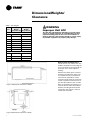
WARNING
Improper Unit Lift!
Test lift unit approximately 24 inches to verify proper
center of gravity lift point. To avoid dropping of unit,
reposition lifting point if unit is not level. Failure to
properly lift unit could result in death or serious injury
or possible equipment or property-only damage.
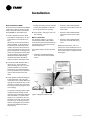
Dimensions/Weights/
Clearance
Figure 2: Mechanical clearances - WPVJ
Unit Location and Clearances
Locate the unit in an indoor area. The
ambient temperature surrounding the
unit must not be less than 45°F. Do not
locate the unit in areas subject to
freezing.
Attention should be given to service
clearance and technician safety. The
unit should be easily maintained or
serviced in all applications. There
must be enough space for service per-
sonnel to perform maintenance or re-
pair. Provide sufficient room to make
water, and electrical connection(s). Lo-
cal and national codes should be fol-
lowed in providing electrical power
connections. See Figure 1 and 2 for
mechanical clearances.
Figure 1: Mechanical clearances - WPHF

WSHP-SVX04A-EN 7
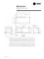
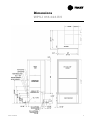
Dimensions
WPHF 021-057

8 WSHP-SVX04A-EN
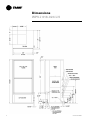
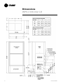
Dimensions
WPVJ 018-024 LH

WSHP-SVX04A-EN 9
Dimensions
WPVJ 018-024 RH

10 WSHP-SVX04A-EN
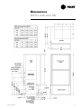
Dimensions
WPVJ 030-042 LH

WSHP-SVX04A-EN 11
Dimensions
WPVJ 030-042 RH

12 WSHP-SVX04A-EN
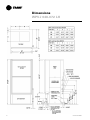
Dimensions
WPVJ 048-072 LH

WSHP-SVX04A-EN 13
Dimensions
WPVJ 048-072 RH

14 WSHP-SVX04A-EN
General Installation Checks
The checklist below is a summary of
the steps required to successfully in-
stall a unit. This checklist is intended to
acquaint the installing personnel with
procedures required in the installation
process. It does not replace the de-
tailed instructions called out in the ap-
plicable sections of this manual.
1 Remove packaging and inspect the
unit. Check the unit for shipping
damage and material shortage; file
a freight claim and notify appropri-
ate sales representation.
Note: The vertical units have been
tied to the skid by (8) shipping
brackets with (16) 5/16" screws.
Remove the (8) screws attached on
the unit side, and (2) screws at-
tached at the L bracket side. The
unit may now be slid off of the
skid. Re-attach (8) of the screws
into the unit base pan.
2 Verify the correct model, options
and voltage from the unit name-
plate.
3 Verify the installation location of
the unit will provide the required
clearance for proper operation.
4 Remove refrigeration access panel
and inspect the unit. Be certain the
refrigerant tubing has clearance
from adjacent parts.
WARNING
Hazardous
Voltage!
Disconnect all electric power,
including remote disconnects
before servicing. Follow proper
lockout/tagout procedures to
ensure the power can not be
inadvertently energized. Failure to
disconnect power before
servicing could result in death or
serious injury.
Main Electrical
5 Verify the power supply complies
with the unit nameplate specifica-
tions.
6 Inspect all control panel compo-
nents; tighten any loose connec-
tions.
7 Connect properly sized and pro-
tected power supply wiring to a
field-supplied/installed disconnect
switch and to the unit contactor
(1K1) in the unit’s cabinet control
box for equipment.
8 Install proper grounding wires to
an earth ground.
Note: All field-installed wiring must
comply with NEC and applicable local
codes.
Low Voltage Wiring (AC & DC)
Requirements
9 Connect properly sized control wir-
ing to the proper termination
points between the thermostat/
sensor and the terminal board in
the unit’s control box.
Filter Installation
10 Each unit ships with 1" filters. Do
not operate the unit without fil-
ters.
Installation

WSHP-SVX04A-EN 15
Unit Installation; WPVJ
Duct collars are provided for the WPVJ
equipment. The duct system and dif-
fusers should be sized inaccordance
with ASHRAE or ACCA Manual D.
1 Install a flexible connector (field
provided) for supply/return air duct
connections on all metal duct sys-
tems.
Note: If the unit is connected to ex-
isting ductwork, an initial check of
the mechanical system should be
made to insure the duct has the ca-
pacity to handle the air required for
the unit application. If ducting is too
small, as in the replacement of heat-
ing only systems, larger ductwork
should be installed. All existing
ductwork should be checked for
leaks, and repairs should be made.
2 Insulate the field ductwork with a
minimum of 1" duct insulation.
Note: Installing the unit to an unin-
sulated ductwork in an uncondi-
tioned space may adversely affect
the unit’s performance, as well as in-
crease noise emissions into the
space.
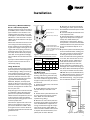
3 Install proper condensate trapping
to the equipment. The unit drain
connection is 3/4" (19mm). When de-
signing the condensate trap, it is im-
portant to consider the unit’s draw-
thru design requiring negative pres-
sure trapping.
In a properly trapping system, when
condensate forms during normal
operation, the water level in the trap
rises until there is a constant flow
(Figure 3). It is imperative to main-
tain water in the trap and not allow
the trap to dry out during heating
season. Keeping the trap primed at
all times will enable the water to
flow properly.
Condensate piping must be installed
to allow the cleanable condensate
pan to be removed for cleaning.
Minimum clearances for drain pan
removal are 22" (sizes 018 and 024),
25" (sizes 030 and 042), and 27" (siz-
es 048 through 072).
4 Flush System. See page 17 for sys-
tem flushing.
Water Connection
For vibration isolation, it is recom-
mended that flexible steel braided
hoses be installed instead of hard pip-
ing between the supply/return risers
and the equipment.
Trane offers 4-types of hose kit varia-
tions:
• Stainless steel braided flexible
hose with manual shut-off (ball)
valves
• Stainless steel braided flexible
hose with manual deluxe shut-off
(ball) valves
• Stainless steel braided flexible
hose with manual circuit-setter
valve
• Stainless steel braided flexible
hose with automatic balancing
valve
Additional accessories, such as a
strainer are recommended for use to
eliminate contaminants from entering
the co-axial water-to-refrigerant heat
exchangers.
Installation
Figure 3: Negative pressure trap

16 WSHP-SVX04A-EN
Unit Installation; WPHF
Duct collars are provided for the WPHF
equipment. The duct system and dif-
fusers should be sized inaccordance
with ASHRAE or ACCA Manual D.
1 Install a flexible connector (field
provided) for supply/return air duct
connections on all metal duct sys-
tems.
Note: If the unit is connected to ex-
isting ductwork, an initial check of
the mechanical system should be
made to insure the duct has the ca-
pacity to handle the air required for
the unit application. If ducting is too
small, as in the replacement of heat-
ing only systems, larger ductwork
should be installed. All existing
ductwork should be checked for
leaks, and repairs should be made.
2 Insulate the field ductwork with a
minimum of 1" duct insulation.
Note: Installing the unit to an unin-
sulated ductwork in an uncondi-
tioned space may adversely affect
the unit’s performance, as well as in-
crease noise emissions into the
space.
3 Install proper condensate trapping
to the equipment. The unit drain
connection is 3/4" (19mm). When de-
signing the condensate trap, it is im-
portant to consider the unit’s draw-
thru design requiring negative pres-
sure trapping.
In a properly trapping system, when
condensate forms during normal
operation, the water level in the trap
rises until there is a constant flow
(Figure 4). It is imperative to main-
tain water in the trap and not allow
the trap to dry out during heating
season. Keeping the trap primed at
all times will enable the water to
flow properly.
Condensate piping must be installed
to allow the cleanable condensate
pan to be removed for cleaning.
4 Flush System. See page 17 for sys-
tem flushing.
Water Connection
For vibration isolation, it is recom-
mended that flexible steel braided
hoses be installed instead of hard pip-
ing between the supply/return risers
and the equipment.
Trane offers 4-types of hose kit varia-
tions:
• Stainless steel braided flexible
hose with manual shut-off (ball)
valves
• Stainless steel braided flexible
hose with manual deluxe shut-off
(ball) valves
• Stainless steel braided flexible
hose with manual circuit-setter
valve
• Stainless steel braided flexible
hose with automatic balancing
valve
Additional accessories, such as a
strainer are recommended for use to
eliminate contaminants from entering
the co-axial water-to-refrigerant heat
exchangers.
Installation
Figure 4: Negative pressure trap

WSHP-SVX04A-EN 17
Connecting a Distributed Pump
Kit to a Closed Loop System
All piping external to the unit is the re-
sponsibility of the installer. The water
pipe installation must be done in ac-
cordance with local codes. If no local
code applies, national codes should be
followed. It is the contractor’s respon-
sibility to know and adhere to all appli-
cable codes.
Water inlet and outlet to the unit’s wa-
ter-to-refrigerant heat exchanger are
clearly marked on the submittal draw-
ings found on pages 7 through 13. The
supply and return piping must be in-
stalled correctly to the unit to ensure
the safety devices will work properly.
Units that are not piped accordingly
will not obtain the manufacturers war-
ranty.
A pump module and hose kit (Figure 5)
may be used to connect the unit to
closed loop piping.
Using Antifreeze
In areas of the country where entering
water temperatures drop below 45°F
or where piping is being run through
areas subject to freezing, the loop
must be freeze protected by using an
approved antifreeze solution to pre-
vent the earth loop water from freez-
ing inside the heat exchanger.
Methanol, Ethylene, and Propylene
Glycol are the most commonly used
antifreeze solutions. Consult your geo-
thermal unit supplier for the best solu-
tions in your area.
Propylene glycol is not recommended
in installations where the water tem-
perature are expected to fall below
30°F. At extreme temperatures, the vis-
cosity increases to the point where
normal loop circulating pumps cannot
maintain proper flow.
Calculate the approximate volume of
water in the system by using the re-
quirements detailed in Table 2. Add
three gallons to this total to allow for
the water contained in the hose kit and
geothermal unit.
Table 2: Required Antifreeze by volume
Cleaning and Flushing
the Water Loop
After the piping system is complete,
cleaning and flushing the water loop
should be done to avoid trash settle-
out in the condenser (Figure 6). An ex-
tra pipe may be necessary to connect
the hose kits.
1 Electrical power to the unit should
be disconnected.
2 Double back the supply hose and
connect directly to the return riser
valve.
3 Fill the water system with clean wa-
ter using the water make up connec-
tions. Note: Air vents should be
opened during filling.
4 With the air vents closed, start the
circulating pump and then crack the air
vents to bleed off the trapped air, as-
suring circulation through all compo-
nents of the system. Note: Make up
water must be available to the system
to replace the volume formerly occu-
pied by the air that is bled off.
Type of
Antifreeze
Minimum Temperature for
Freeze Protection
10°F 15°F 20°F 25°F 30°F
Methanol 25% 21% 16% 10% 3%
Propylene
Glycol
23% 21% 19% 9% 6%
Ethylene Glycol 20% 19% 16% 14% 12%
5 With the air vented and the water
circulating, the entire system should
be checked for leaks with repairs made
as required.
6 Check and adjust the water/air level
in the expansion tank.
7 Operate the boiler (if used) by rais-
ing the loop temperature to approxi-
mately 85°F. Make checks per
manufacturer’s instructions. During
this operation, visual checks should be
made for leaks that may have occurred
due to increased heat. Repair as re-
quired.
8 Open the system at the lowest point
for the initial blow down (making sure
the make up water is equal to the wa-
ter being dumped). Continue blow
down until the water leaving the drain
runs clear, but not less than 2 hours.
9 Shut down pumps and boiler (if
used). Reconnect the hoses to the
proper supply/return for each unit,
placing the water-to-refrigerant heat
exchanger in the water circulating sys-
tem. Note: Vents should be open when
the pumps and boiler are shut down.
10 Refill the system and bleed off any
air. Add antifreeze to the system in cli-
mates where ambient temperature
falls below freezing, using the propor-
tion of antifreeze shown in Table 2.
Installation
From Units
W.O.
To Units
W.I.
Bronze or Cast Iron Pump
Purging Cap (2)
Shut-off 3-way Valve (2)
1" MPT x barb fittings
1" MPT x barb elbows with
pressure temperature ports
and 10’ of rubber hose with
4 hose clamps
Figure 5: Pump module and hose kit
Figure 6: System flushing

18 WSHP-SVX04A-EN
Field Installed Power Wiring
Power wiring to the equipment must
conform to National and Local Electric
Codes (NEC) by a professional electri-
cian.
WARNING
Live Electrical
Components!
During installation, testing, ser-
vicing and troubleshooting of this
product, it may be necessary to
work with live electrical compo-
nents. Have a qualified licensed
electrician or other individual
who has been properly trained in
handling live electrical compo-
nents perform these tasks. Failure
to follow all electrical safety pre-
cautions when exposed to live
electrical components could re-
sult in death or serious injury.
Verify that the power supply available
is compatible with the unit’s name-
plate. Use only copper conductors to
connect the power supply to the unit.
CAUTION
Use Copper
Conductors Only!
Unit terminals are not designed
to accept other types of conduc-
tors. Failure to use copper con-
ductors may result in equipment
damage.
Main Unit Power Wiring
A field supplied disconnect switch
must be installed at or near the unit in
accordance with the National Electric
Code (NEC latest edition).
Location of the applicable electric ser-
vice entrance for HIGH (line voltage)
may be found on the unit submittals
(pages 7 to 13).
1 The high voltage connection is
made at the 1K1 contactor inside of
the unit control box. Refer to the
connection diagram that is shipped
with the unit for specific termina-
tion points.
2 Provide proper grounding for the
unit in accordance with the local
and national codes.
Control Power Transformer
The 24-volt control power transform-
ers are to be used only with the acces-
sories called out in this manual.
Transformers rated greater than 50 VA
are equipped with internal circuit
breakers. If a circuit breaker trips, turn
OFF all power to the unit before at-
tempting to reset it.
WARNING
Hazardous Voltage!
Disconnect all electric power, in-
cluding remote disconnects be-
fore servicing. Follow proper
lockout/tagout procedures to en-
sure the power can not be inad-
vertently energized. Failure to
disconnect power before servic-
ing could result in death or seri-
ous injury.
The transformer is located in the
unit’s control box.
Installation

WSHP-SVX04A-EN 19
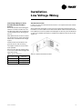
Low Voltage Wiring for Field
Provided Thermostats/Zone
Sensors
Ensure that the AC control wiring be-
tween the controls and the unit’s ter-
mination point does not exceed three
(3) ohms/conductor for the length of
the run.
Note: Resistance in excess of 3-ohms
per conductor may cause component
failure due to insufficient AC voltage
supply.
Check all loads and conductors for
grounds, shorts, and mis-wiring.
Use copper conductors unless other-
wise specified.
Do not run the AC low voltage wiring
in the same conduit with the high volt-
age power wiring.
Table 3: 24V AC conductors
Distance
from unit to Control
Recommended
Wire Size
000-460 feet 18 gauge
461-732 feet 16 gauge
733-1000 feet 14 gauge
Thermostat Location
Location of the room thermostat/zone sensor cis an important element of effec-
tive room control.
Areas where the thermostat or zone sensor should not be located include : be-
hind doors, or corners; Near hot or cold air ducts; Near radiant heat (heat emitted
from appliances or the sun); Near concealed pipes or chimneys; On outside walls
or other non conditioned surfaces; In airflows from adjacent zones or other units
(Figure 7).
Installation
Low Voltage Wiring
Figure 7: Thermostat/sensor location

20 WSHP-SVX04A-EN
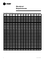
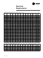
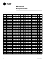
Table E1: WPVJ Electrical Performance (Standard Static Blower Option)
Model
No.
Volts/Hz/Ph Total
FLA
Comp.
RLA (ea)
Comp.
LRA (ea)
No. of
Compres.
Cmp
MCC
Blower
Motor
FLA
Blower
Motor
HP
Fan Motor
Num
Minimum
Circuit
Ampacity
Overcurrent
Protective
Device
Desup Desup
RLA
WPVJ018 208/60/1 10.1 9.30 47.0 1 13.0 0.80 1/8 1 12.4 20 No 0
WPVJ018 208/60/1 10.31 9.30 47.0 1 13.0 0.80 1/8 1 12.6 20 Yes 0.21
WPVJ018 220-240/50/1 9.81 8.60 39.0 1 12.0 1.00 1/5 1 12.0 20 No 0.21
WPVJ018 230/60/1 10.1 9.30 47.0 1 13.0 0.80 1/8 1 12.4 20 No 0
WPVJ018 230/60/1 10.31 9.30 47.0 1 13.0 0.80 1/8 1 12.6 20 Yes 0.21
WPVJ018 265/60/1 9.6 8.60 39.0 1 12.0 1.00 1/5 1 11.8 20 No 0
WPVJ018 265/60/1 9.81 8.60 39.0 1 12.0 1.00 1/5 1 12.0 20 Yes 0.21
WPVJ024 208/60/1 12.6 11.40 56.0 1 16.0 1.20 1/5 1 15.5 25 No 0
WPVJ024 208/60/1 12.81 11.40 56.0 1 16.0 1.20 1/5 1 15.7 25 Yes 0.21
WPVJ024 220-240/50/1 10.6 9.60 47.0 1 13.5 1.00 1/5 1 13.0 20 No 0
WPVJ024 230/60/1 12.6 11.40 56.0 1 16.0 1.20 1/5 1 15.5 25 No 0
WPVJ024 230/60/1 12.81 11.40 56.0 1 16.0 1.20 1/5 1 15.7 25 Yes 0.21
WPVJ024 265/60/1 10.81 9.60 47.0 1 13.5 1.00 1/5 1 13.2 20 Yes 0.21
WPVJ024 265/60/1 10.6 9.60 47.0 1 13.5 1.00 1/5 1 13.0 20 No 0
WPVJ030 208/60/1 15.1 13.60 67.0 1 19.0 1.50 1/4 1 18.5 30 No 0
WPVJ030 208/60/1 15.31 13.60 67.0 1 19.0 1.50 1/4 1 18.7 30 Yes 0.21
WPVJ030 220-240/50/1 13.4 12.10 58.0 1 17.0 1.30 1/4 1 16.4 25 No 0
WPVJ030 230/60/1 15.1 13.60 67.0 1 19.0 1.50 1/4 1 18.5 30 No 0
WPVJ030 230/60/1 15.31 13.60 67.0 1 19.0 1.50 1/4 1 18.7 30 Yes 0.21
WPVJ030 265/60/1 13.4 12.10 58.0 1 17.0 1.30 1/4 1 16.4 25 No 0
WPVJ030 265/60/1 13.61 12.10 58.0 1 17.0 1.30 1/4 1 16.6 25 Yes 0.21
WPVJ036 208/60/1 17.8 15.00 73.0 1 21.0 2.80 1/3 1 21.6 35 No 0
WPVJ036 208/60/1 18.01 15.00 73.0 1 21.0 2.80 1/3 1 21.8 35 Yes 0.21
WPVJ036 208/60/3 13.5 10.70 63.0 1 15.0 2.80 1/3 1 16.2 25 No 0
WPVJ036 208/60/3 13.71 10.70 63.0 1 15.0 2.80 1/3 1 16.4 25 Yes 0.21
WPVJ036 220-240/50/1 16.6 14.30 71.0 1 20.0 2.30 1/3 1 20.2 30 No 0
WPVJ036 230/60/1 17.8 15.00 73.0 1 21.0 2.80 1/3 1 21.6 35 No 0
WPVJ036 230/60/1 18.01 15.00 73.0 1 21.0 2.80 1/3 1 21.8 35 Yes 0.21
WPVJ036 230/60/3 13.5 10.70 63.0 1 15.0 2.80 1/3 1 16.2 25 No 0
WPVJ036 230/60/3 13.71 10.70 63.0 1 15.0 2.80 1/3 1 16.4 25 Yes 0.21
WPVJ036 265/60/1 16.6 14.30 71.0 1 20.0 2.30 1/3 1 20.2 30 No 0
WPVJ036 265/60/1 16.81 14.30 71.0 1 20.0 2.30 1/3 1 20.4 30 Yes 0.21
WPVJ036 380-415/50/3 6.1 5.00 31.0 1 7.0 1.10 1/3 1 7.4 15 No 0
WPVJ036 460/60/3 6.1 5.00 31.0 1 7.0 1.10 1/3 1 7.4 15 No 0
WPVJ036 460/60/3 6.31 5.00 31.0 1 7.0 1.10 1/3 1 7.6 15 Yes 0.21
WPVJ042 208/60/1 21.3 18.40 95.0 1 25.8 2.90 1/2 1 25.9 40 No 0
WPVJ042 208/60/1 21.51 18.40 95.0 1 25.8 2.90 1/2 1 26.1 40 Yes 0.21
WPVJ042 208/60/3 14.3 11.40 77.0 1 16.0 2.90 1/2 1 17.2 25 No 0
WPVJ042 208/60/3 14.51 11.40 77.0 1 16.0 2.90 1/2 1 17.4 25 Yes 0.21
WPVJ042 230/60/1 21.3 18.40 95.0 1 25.8 2.90 1/2 1 25.9 40 No 0
WPVJ042 230/60/1 21.51 18.40 95.0 1 25.8 2.90 1/2 1 26.1 40 Yes 0.21
WPVJ042 230/60/3 14.3 11.40 77.0 1 16.0 2.90 1/2 1 17.2 25 No 0
WPVJ042 230/60/3 14.51 11.40 77.0 1 16.0 2.90 1/2 1 17.4 25 Yes 0.21
WPVJ042 380-415/50/3 7.1 5.70 39.0 1 8.0 1.40 1/2 1 8.5 15 No 0
WPVJ042 460/60/3 7.1 5.70 39.0 1 8.0 1.40 1/2 1 8.5 15 No 0
WPVJ042 460/60/3 7.31 5.70 39.0 1 8.0 1.40 1/2 1 8.7 15 Yes 0.21
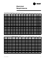
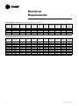
Electrical
Requirements
Page is loading ...
Page is loading ...
Page is loading ...
Page is loading ...
Page is loading ...
Page is loading ...
Page is loading ...
Page is loading ...
Page is loading ...
Page is loading ...
Page is loading ...
Page is loading ...
Page is loading ...
Page is loading ...
Page is loading ...
Page is loading ...
Page is loading ...
Page is loading ...
Page is loading ...
-
 1
1
-
 2
2
-
 3
3
-
 4
4
-
 5
5
-
 6
6
-
 7
7
-
 8
8
-
 9
9
-
 10
10
-
 11
11
-
 12
12
-
 13
13
-
 14
14
-
 15
15
-
 16
16
-
 17
17
-
 18
18
-
 19
19
-
 20
20
-
 21
21
-
 22
22
-
 23
23
-
 24
24
-
 25
25
-
 26
26
-
 27
27
-
 28
28
-
 29
29
-
 30
30
-
 31
31
-
 32
32
-
 33
33
-
 34
34
-
 35
35
-
 36
36
-
 37
37
-
 38
38
-
 39
39


Ask a question and I''ll find the answer in the document
Finding information in a document is now easier with AI
Related papers
-
Trane GEH User manual
-
-
-
Trane Axiom GEVE018 Installation and Maintenance Manual
-
-
Trane Axiom GEH036 User manual
-
-
-
-
Other documents
-
Smeg SMEG500GRUS Bulletin
-
Enertech VC Series Engineering Data And Installation Manual
-
Sansui SLEDVD198 Datasheet
-
McQuay Enfinity series Installation & Maintenance Data
-
 Heat Controller Flow Controllers Installation, Operation & Maintenance Manual
-
Stelpro SDHx Series User guide
-
 TTHERM GEO THT-120 Installation guide
-
Carrier 50RHE006-060 User manual
-
-

