Braeburn 500 User manual

Category
Thermostats
Type
User manual

This manual is also suitable for

1
MODELS
500 1 HEAT/1 COOL
505 HEAT ONLY
USER MANUAL
Builder Series
Mercury-Free Mechanical Thermostats
with the Exclusive Megaswitch
®
Magnetic Switch Technology
Compatible with low voltage, single stage gas, oil or electric heating or
cooling systems. Model 500 can be used with single stage heat pumps.
Models 500 & 505 can also be used on 250mv to 750mv millivolt heat only
systems. Do not use on applications with voltages above 30 Volts AC.
READ ALL INSTRUCTIONS BEFORE PROCEEDING
WARNING!
Important Safety
Information
Always turn off power to air conditioning or heating system prior to installing, removing cleaning or servicing thermostat.
Read this manual thoroughly prior to installing or operating this thermostat.
This thermostat is designed for use with 24 Volt-AC low voltage single stage gas, oil or electric heating or cooling systems,
including single stage heat pumps (Model 500 only). This thermostat can also be used on 250mv to 750mv millivolt heating
only systems (Models 500 and 505).
Do not use this thermostat on applications with voltage above 30 Volts AC.
The system must have 24 Volt AC present for proper system operation and control.
Wiring must conform to all building codes and ordinances as required by local and national code authorities
having jurisdiction.
Do not short (or jumper) across terminals on the gas valve or at the heating or cooling system control board to test the
thermostat installation. This could damage the thermostat and void the warranty.
Do not select COOL mode of operation if the outside temperature is below 50° F (10° C). This could possibly damage the
controlled cooling system and may cause personal injury.
This thermostat should only be used as described in this manual. Any other use is not recommended and will void warranty.
SPECIFICATIONS
1
Electrical Rating: 24 Volt AC (18-30 Volt AC), 250 – 750 millivolts
Heat Anticipation: 0.15 to 1.2 amps.
Temperature Range: 50° - 90° F (10° - 32° C)
Old Terminal New Terminal Terminal Description
V or Rc Rc Cooling Transformer
M, 4, Rh or R Rh Heating Transformer
O O Reversing Valve (Cooling)
B B Reversing Valve (Heating)
Y Y Cooling or Compressor for HP system
H, W or 4 W Heating Control
G or F G Fan Control
INSTALLATION
2
1. Always turn off power to the air conditioning or heating system prior to removing existing thermostat.
2. Remove the cover of old thermostat and locate wire terminals. Do not remove wires from terminals yet.
3. Label wires prior to removal from terminals. Use chart below to determine new terminal designations for new thermostat.
2.1
Replacing Existing Thermostat
2.2
Installing Your New Thermostat
NOTE: This thermostat is designed for use with a 24 Volt AC low voltage single stage gas, oil or electric heating or cooling
systems, including single stage heat pumps (Model 500 only). This thermostat can also be used on 250mv to 750mv millivolt
heating only systems (Models 500 and 505). Do not use this thermostat on applications with voltages above 30 Volts AC.
1. Always turn off power to the air conditioning or heating system prior to installing new thermostat.
2. Place system lever to OFF position, and fan control lever to AUTO position.
3. Remove the front cover of the thermostat by firmly pulling it away from the base.
4. Place thermostat base against wall in the desired thermostat location and guide thermostat wires through
vertical slot in base.
5. Mark placement of mounting holes as appropriate and drill using a 3/16” drill bit.
6. Gently tap supplied plastic anchors into the holes in the wall.
7. Place the thermostat base against the wall in the desired location making sure the mounting holes are aligned and the
thermostat wires are properly inserted through the slotted opening in the base.
NOTE: If installing this thermostat in a new installation, be sure to locate the thermostat about 4 to 5 feet above the
floor in accordance with applicable building codes. Be sure to install thermostat in a location that provides good airflow
characteristics and avoid areas behind doors, near corners, air vents, direct sunlight or near any heat generating device.
Installation in any of these areas could impact thermostat performance.
8. Fasten the base to wall using supplied screws.
9. Connect wires to proper terminal screws using new terminal designations (see Wiring Diagrams section of manual).
10. Make sure all of the wire connections are secure and are not touching any other terminal to prevent electrical shorts
and potential damage to the thermostat.
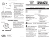
11. Locate the internal fan option jumper, HG (Gas) or HE (Elec) on the base (Model 500 only). This jumper controls the
heating system fan delay. Insert the jumper over the pins labeled HG for gas or oil fired systems. This will allow the
furnace to run for a few seconds before the fan starts. Insert the jumper over the pins labeled HE for electric
systems with electric furnace elements or heat pump systems that require the fan to come on immediately.
12. Attach front cover of thermostat to base of the thermostat by pressing it onto the four corner posts of base.
13. Restore system power so you can test installation.
4. After labeling and removing all wires from terminals, unscrew the existing thermostat mounting base from wall. Be sure
to secure wires to prevent them from slipping back into the hole in the wall.
2
2.3
Setting the Heat Anticipator
NOTE: Some heating systems require a longer or shorter “ON/OFF” period to maintain comfort.
Set the heat anticipator as specified in one of the following conditions:
For replacement installations match the anticipator setting with that of the thermostat being replaced.
For new installations match the current draw (amperage) of the heating control or relay. To do this check the rating
label on the control within the heating system. If the label cannot be found, determine circuit amperage by:
INSTALLATION
2
cont.
WARNING: Thermostat will not function if
anticipator handle covers PC board cutout.
1. Place system lever in the HEAT position.
2. Adjust temperature lever until indicator is at least 3 degrees above the room temperature. The heating system should start
within several seconds. Fan may not turn on immediately due to the heating system built-in fan delay.
3. Place system lever in the OFF position. The heating system should stop within several seconds.
The adjustable heat anticipator will burn out if 25 Volts are applied directly to the thermostat by shorting out the gas valve
or primary control during testing or by improper wiring.
WARNING!
TESTING YOUR NEW THERMOSTAT
3
WARNING!
Read BEFORE Testing
Do not short (or jumper) across terminals on the gas valve or at the heating or cooling system control board to test
the thermostat installation. This could damage the thermostat and void the warranty.
Do not select COOL mode of operation if the outside temperature is below 50° F (10° C). This could possibly
damage the controlled cooling system and may cause personal injury.
.2
.3
.4
.5
.6
.8
1.0
L
O
N
G
E
R
C
Y
C
L
E
S
1. Slide the system lever to OFF, or set temperature to lowest setting
so that the contacts are open. Make sure system power is
turned back on.
2. Set an AC ammeter to the 0 to 1 amp. range. Place the meter
probes on W and Rh terminals. The heating valve or relay will turn
“ON” and a reading will appear on the meter. Note this reading.
Remove the probes from the terminals.
3. Set the heat anticipator arrow to this meter reading. This is the
normal setting.
4. The anticipator adjustment must be made so that the thermostat
is in “balance” with the rest of the system. It will determine how
often the heating system turns on and off.
NOTE: If installing on a millivolt heat only system, set the
anticipator to the maximum setting of 1.2.
NOTE: Allow the heating system to operate for a full day or more.
Too frequent cycling of the heating system can result in lower life
expectancy for the heating system. If adjustments are necessary,
make them in 0.1 amp increments at a time. Move the anticipator
lever in direction of arrow to cycle less often.
3
5
SYMPTOM POTENTIAL SOLUTION
Thermostat does not turn
on heating or cooling
system.
Thermostat turns on
heating instead of cooling,
or cooling instead of
heating.
Check thermostat wiring to be sure that the heating and cooling stages are connected to the
correct terminals. See Installation and Wiring Diagrams sections of this manual.
Thermostat turns heating
system on too often or not
often enough.
Increase or decrease anticipator setting as appropriate to provide the desired performance
level. See Setting Heat Anticipator section of this manual.
Fan continues to run all
the time whether the
system is on or off.
Check that the fan control lever is in the AUTO position. This will allow the fan to run only
when the heating or cooling system is turned on and running.
Check thermostat wiring to make sure that the fan control wiring is connected to the correct
terminal. See Installation and Wiring Diagrams sections of this manual.
Check to see if system lever is in the OFF position. This indicates that the system is turned
OFF at the thermostat. Move the system lever to either the HEAT or COOL position.
Heating or cooling system may be malfunctioning. Call a professional service technician
immediately to verify system operation.
TESTING YOUR NEW THERMOSTAT
3
cont.
4. Place system lever in the COOL position.
5. Adjust temperature lever until indicator is at least 3 degrees lower than room temperature. The cooling system should
start within several seconds.
6. Place system lever in the OFF position. The cooling system should stop within several seconds.
7. Place fan lever in the ON position. The system blower should start.
8. Place fan lever in the AUTO position. The system blower should stop.
For heat pumps, DO NOT place system lever back in the HEAT position for a few minutes. Quick repetitive cycles of the
system compressor can lead to damage and shorten its life expectancy.
DO NOT place the system lever back in the COOL position for a few minutes. Quick repetitive cycles of the cooling system
compressor can lead to damage and shorten its life expectancy.
WARNING!
WARNING!
1. Set the system lever to either HEAT or COOL.
2. Adjust the temperature lever to the desired setpoint temperature.
4
USING YOUR NEW THERMOSTAT
TROUBLESHOOTING
4
©2013 Braeburn Systems LLC • All Rights Reserved. 500-100-04
Braeburn Systems LLC
2215 Cornell Avenue • Montgomery, IL 60538
Technical Assistance: www.braeburnonline.com
Phone: 866-268-5599
When installed by a professional contractor, this product is backed by a 1 year limited warranty. Limitations apply. For limitations,
terms and conditions, you may obtain a full copy of this warranty:
· Visit us online: www.braeburnonline.com/warranty
· Phone us: 866.268.5599
· Write us: Braeburn Systems LLC
2215 Cornell Avenue
Montgomery, IL 60538
WIRING DIAGRAMS
6
Typical 4-Wire Single Transformer Heating and Cooling System
O G W
Factory Installed
Jumper
Y
BRc Rh
Cool
Control
Heat
Control
120
Volt AC
Hot Side Transformer
24 Volt AC
Transformer
Fan
Control
Typical 5-Wire Two Transformer Heating and Cooling System
O G W
Remove
Factory Installed
Jumper
YBRc Rh
Cool 24 VAC
Transformer
120
Volt AC
Heat 24 VAC
Transformer
120
Volt AC
Hot Side Cool
Transformer
Heat
Control
Fan
Control
Cool
Control
Hot Side Heat
Transformer
Typical Single Stage Heat Pump Reversing Valve Active in Cooling
O G W
Factory Installed
Jumper
Y
BRc Rh
24 Volt AC
Transformer
120
Volt AC
Hot Side Transformer
Fan
Control
See Note 1
NOTES: 1. For Model 505 with Electric Heat, if fan wire is present connect to “W” terminal.
2. For 2-Wire 24 Volt AC or 250mV – 750mV Millivolt Heating Only Systems, remove factory installed jumper.
cont.
WIRING DIAGRAMS
6
NOTES: 1. Installer must place jumper wire between “W” and “Y” terminals.
2. For Typical Single Stage Heat Pump Reversing Valve Active in Heating, reversing valve
must be connected to “B” terminal instead of “O” terminal.
ONE YEAR LIMITED WARRANTY
Compressor
Control
Reversing
Valve
  • Page 1 1
  • Page 2 2
  • Page 3 3

Braeburn 500 User manual

Category
Thermostats
Type
User manual
This manual is also suitable for

Ask a question and I''ll find the answer in the document

Finding information in a document is now easier with AI