Page is loading ...

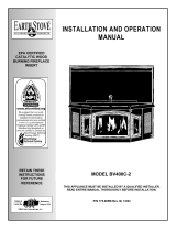
Homeowner’s
Installation and
Operating Manual
20005167 5/11 Rev. 18
5167
EPA36
cover
3/02

2
Vermont Castings EWF36A
20005167
Thank you for purchasing a Vermont Castings, EWF36A replace. An efcient replace carefully engineered to bring
you the latest in wood combustion principles and modern foundry technology.
You can count on years of comfortable heating and pleasurable re viewing if you treat it properly and operate the
EWF36A according to the directions in this owner’s guide.
The EWF36A is listed by Underwriter’s Laboratories, and is in compliance with the standards set forth by the Federal
Environmental Protection Agency, 40 CFR Part 60.532(b), as stated on the permanent label attached to each appli-
ance.
This manual describes the installation and operation of the EWF36A wood heater. This heater meets the US Environ-
mental Protection Agency’s emission limits for wood heaters sold after July 1, 1990. Under specic test conditions this
heater has been shown to deliver heat at a rate ranging from 11,000 to 68,600 Btu’s/hr.
For more complete details on the EWF36A performance and specications, please refer to Page 3.
The EWF36A is designed, tested and listed for burning wood. Do not burn other fuels.
Installation or service of this woodburning rep should only be completed by a qualied installer, preferably NFI or
WETT (Canada) certied.
Please read the appropriate sections of this manual before you install and use your EWF36A. For information on op-
eration and maintenance of the EWF36A, refer to Pages 17 and 20.
The EWF replace can use 100% outside air with the AKMST Outside Air Kits installed.
Failure to follow these instructions may result in property damage, bodily injury or even death.
Introduction ................................................................ 2
Safety Information ..................................................... 3
Specications ............................................................ 4
Planning Information.................................................. 7
Installation ................................................................. 8
Operation ................................................................. 18
Maintenance ............................................................ 22
Replacement Parts .................................................. 27
Optional Accessories ............................................... 29
Warranty .................................................................. 31
Fuels used in gas, wood-
burning or oil red appliances, and the products of
combustion of such fuels, contain chemicals known
to the State of California to cause cancer, birth de-
fects and other reproductive harm.
California Health & Safety Code Sec. 25249.6

3
Vermont Castings EWF36A
20005167
Read all instructions and warnings carefully before starting installation. Failure to
follow these instructions may result in a possible re hazard and will void the warranty.
The EWF36A replace is a solid fuel, woodburning,
heat circulating replace.
MHSC replaces and component parts have been
highly tested and will operate safely when installed in
accordance with instructions provided in this manual.
Carefully read and understand all instructions
beginning installation.
If you notice any damage to replace or component
parts, immediately report damage to your MHSC dealer.
Only use MHSC components or the warranty will be
voided and a re hazard may be created.
MHSC warranty will be voided by and MHSC disclaims
any responsibility for the following actions:
•
•
•
(except for
chase ashings as detailed in MHSC Chimney
Top installation instructions).
•
•
Consult local building codes to ensure that you are in
compliance installing the replace.
This replace and chimney system must be vented to
the out-of-doors.
The replace should not be located in areas that create
drafts (ie: frequently opened doors and central heating
air inlets/outlets) that hamper the normal ow of air into
the re.

4
Vermont Castings EWF36A
20005167
Range of heat output*................ 11,300 - 75,500 Btu/hr
Maximum heat output** ..... in excess of 100,000 Btu/hr
EPA emissions rating (g/h, catalytic) .......................2.4*
Area heated*** ............... Up to 2500 sq. ft. (558 sq. m)
Size of wood splits .....................18” - 24” (450-610mm)
Fuel Capacity............................................ 40lbs. (18kg)
Loading ..................................................................Front
Flue size ..................................................... 8” (200mm)
Fireplace weight ................................................ 741lbs.
Primary Air Control ............................................ Manual
Glass panel.......................... High-temperature ceramic
Flue exit position...................................................... Top
Blower rating................................160cfm. (115V, 60Hz)
*Under specic test conditions used during EPA emis-
sions standard testing.
**This value can vary depending on how the unit is
operated, and the type and moisture content of the fuel
used. Figure shown is based on maximum fuel con-
sumption obtained under laboratory conditions and on
average efciencies.
***These values are based on operation in building-
code conforming homes under typical winter climate
conditions. If your home is of nonstandard construction
(e.g. unusually well insulated, not insulated, built under
ground, etc.) or if you live in a more severe or more
temperate climate, these gures may not apply. Since
so many variables affect performance, consult your Ver-
mont Castings’ Authorized Dealer to determine realistic
expectations for your home.
" (25mm)
"
6"
(16mm)
Recessed
Nailing
Flange
5167
EPA36 specs
1356O" Dia.
(343mm)
Rough Opening Width 43"
Rough
Opening
Height
Rough
Opening
Depth
6756M" (1708mm)
6756M" (1708mm)
47
56O" (1207mm)
5/8" (16mm)
95" (2413mm)
27"
(686mm)
26"
(660mm)
856O"
(216mm)
(1092mm)
41" (1041mm)
4756O"
(1207mm)
5156O"
(1308mm)
36" (914mm)
41" (1041mm)
1456M"
(362mm)
1456M"
(362mm)
12(6"
(327mm)
4(6"
(124mm)
1256O"
(318mm)
Electrical
Access
Outside
Air
12(6"
(327mm)
EWF36A specications and framing.

5
Vermont Castings EWF36A
20005167
Fireplace and chase parts identication.
FP554a
FP554a
BFC
Fireplace and chase parts identification
circulating model
8/21/00 djt
Insulation methods shown are
optional for cold climate, not a
requirement for unit operation.
Termination Cap
Storm Collar
Pan Flashing
Draftstop
Batt Insulation
(cut out around
restop)
Firestop
Ceiling Level
Standoff
Metal Safety Strips
(1,2 or 3 pieces)
Batt Insula-
tion be
used in the
Chase.
Outside Air
Cover Plate
Andiron
Brick Ledge

6
Vermont Castings EWF36A
20005167
D
Rise
B
G
H
B
Offset
C
E
6 FT.
G
H
A
Hearth
Floor
Chimney
Section
CHIMNEY FLUE EXIT
Elbow
FP269
MBUF
5/16/96
rev. 5/25
TCS8A
Support
Example 1 Example 2 Example 3
G + H cannot exceed 20 feet.
Air Space Clearances: “S” Series (3-wall) = 2” Min. to Combustibles
The following safety rules apply to
offset installations (letters correspond
with illustration above):
Height of the chimney is measured
from the hearth to the chimney exit.
EWF36A
Maximum: 50’
Minimum:
Without Elbows 17’0”
With 2 Elbows* 19’0”
With 4 Elbows* 21’0”
Do not use more than 4 elbows per
chimney.
Attach the straps of the return (top)
elbow to a structural framing member.
The offset (rst) elbow of any pair does
not have straps.
FP269
The chimney cannot be more than 30˚
(45˚ in Canada) from the vertical plane in
any installation*.
The maximum length of the angled run
of the chimney system is 20 feet. (G
plus H cannot exceed 20 feet.)
A chimney support (Model TCS8A)
is required every 6 feet of angled run of
chimney. Chimney supports are required
for every 30 feet and 60 feet of vertical
chimney height above the hearth.
Determine the offset distance of your
chimney arrangement from the centerline
of the replace to the centerline of the
chimney where it is to pass through the
rst ceiling.
This offset distance may not be
your full offset distance. See Examples 2
and 3.
Chimney system requirements.
FP282
0 0 0 0 0 3” 11”
1 0 0 0 0 8¹⁄₄" 20"
0 1 0 0 0 11¹⁄₄" 25¹⁄₄"
2 0 0 0 0 13¹⁄₂" 29¹⁄₄"
1 1 0 0 0 16¹⁄₂" 34¹⁄₄"
0 0 1 0 0 20¹⁄₄" 40³⁄₄"
2 1 0 0 0 21³⁄₄" 43¹⁄₂"
0 0 0 1 0 26¹⁄₄" 51¹⁄₄"
0 1 1 0 0 28¹⁄₂" 55¹⁄₄"
1 0 0 1 0 31¹⁄₂" 60¹⁄₄”
0 1 0 1 0 34¹⁄₂" 65¹⁄₂"
0 0 2 0 0 37¹⁄₂" 70³⁄₄"
1 1 0 1 1 41¹⁄₂" 77³⁄₄"
0 0 1 1 1 45" 83³⁄₄"
0 1 2 0 1 47¹⁄₄" 87¹⁄₂"
0 0 0 2 1 51" 94"
0 1 1 1 1 53¹⁄₄" 98"
0 0 3 0 1 56¹⁄₄" 103¹⁄₄"
0 1 0 2 1 59¹⁄₄" 108¹⁄₂"
0 0 2 1 1 62¹⁄₄" 113¹⁄₂"
0 1 3 0 1 64¹⁄₂" 117¹⁄₂"
0 0 1 2 1 68¹⁄₄" 124"
0 1 2 1 1 70¹⁄₂" 128"
0 0 0 3 1 74¹⁄₄" 134¹⁄₂"
0 1 1 2 2 78" 140³⁄₄"
0 0 3 1 2 81" 146"
0 1 0 3 2 84" 151¹⁄₄"
0 0 2 2 2 87" 156¹⁄₂"
0 1 3 1 2 89¹⁄₄" 160¹⁄₄"
0 0 1 3 2 93" 166³⁄₄"
0 1 2 2 2 95¹⁄₄" 170³⁄₄"
0 0 0 4 2 99¹⁄₄" 177³⁄₄"
0 1 1 3 2 101¹⁄₄" 181³⁄₄"
0 0 3 2 2 104¹⁄₄" 186¹⁄₄"
0 1 0 4 2 107¹⁄₄" 191¹⁄₂"
0 0 2 3 2 110¹⁄₄" 196³⁄₄"
0 1 3 2 3 114" 203¹⁄₄"
0 0 1 4 3 117³⁄₄" 209³⁄₄"
0 1 2 3 3 120" 213¹⁄₂"
0 0 0 5 3 123³⁄₄" 220"
¹⁄₂
FP282
MBUF
5/26/96
Offset
Rise
30°
Return
Elbow
30°
Return
Elbow
30°
Offset
Elbow
30°
Offset
Elbow

7
Vermont Castings EWF36A
20005167
Determine how the chimney will be run, length of run
and chimney components required to complete the
job. (Fig. 4) install a chimney below minimum
heights.
In planning a chimney system, it is important to know:
1. The height of a chimney is measured from the hearth
to the exit point on the termination.
2. A chimney cannot be offset more than 30° from a
vertical plane.
3. A chimney may run straight up or it may be neces-
sary to offset it to avoid obstructions.
4. The maximum length of an angled run (total chimney
system) is 20 feet.
5. No more than 2 offsets (4 total 30° elbows in U.S./or
2 total 45° elbows in Canada) per replace may be
used.
6. A guy wire stabilizer is required for chimneys extend-
ing more than 6’ (1.8m) above a roof line.
Major U.S. building codes specify a minimum chimney
height above the roof top. The “Ten Foot Rule” is a re
safety rule and not a draft rule. To ensure proper draft,
it is recommended that you always meet or exceed the
“Ten Foot Rule,” especially when installing a termination
on a high pitch roof. (Fig. 5)
The key points of the “Ten Foot Rule” are:
1. If the horizontal distance from the chimney to the
peak of the roof is 10’ (3m) or less, the top of the
chimney must be at least 2’ (610mm) above the peak
of the roof, but never less than 3’ (914mm) in height
above the highest point where it passes through the
roof.
2. If a horizontal distance from the chimney to the peak
of the roof is more than 10’ (3m), a chimney height
reference point is established that is on the surface
of the roof a distance of 10’ (3m) from the chimney in
a horizontal plane. The top of the chimney must be
at least 2’ (610mm) above the reference point, but
never less than 3’ (914mm) in height above the high-
est point where it passes through the roof.
2' Min.
2' Min.
3'
Min.
0 To 10'
3'
Min.
0 To 10'
AC246
4/1/96
Reference
Point
AC246
Ten Foot Rule illustration.
Planning an installation is very important to ensure
safety and to save time and money. An installer must
predetermine where a replace will be set and how the
chimney system will be run.
If installing the EWF36CFTK at a later date and
if the hearth is being raised in front of the repalce, the
replace must be raised to the same height.
The replace is shipped with lifting handles attached to
each side with lifting straps. The lifting straps
are intended for ligting unit off of the skid and nal po-
sitioning. Unit should remain on skid until nal position-
ing. After replace is in position, the lifting handle and
straps may be removed or left in place.
A replace may only be mounted on the following sur-
faces:
1. A at combustible surface.
2. A raised wooden platform.
3. A concrete block or other solid object placed beneath
each of the four (4) corners of the replace.
The replace be spaced 1” from a combustible
back wall and 1” from a combustible side wall or sup-
port. (Page 13, Fig. 17)
L
1
L
1
L
T
TOTAL
LENGTH
(L
T
)
INSTALLED
LENGTH
(L
1
)
56O
"
56O
"
56O
"
56O
"
56O
"
56O
"
56O
"
56O
"
FP288A
MBUF-INSTALLED LENGTH
Triple wall
1/28/99 djt
TRIPLE
WALL
81
818
83
84
FP288a
Installed lengths of chimney sections.

8
Vermont Castings EWF36A
20005167
The chimney system is supported by the replace for
vertical chimney heights less than 30’ (9m) above the
hearth. Chimney supports are required if the vertical
height exceeds 30’ (9m). Locate chimney supports
at ceiling holes or other structural framing at 30’ (9m)
heights. Spacing between chimney supports
exceed 30’ (9m). Use Chimney Support Model TCS8A.
Support provided by elbow straps fullls
the support requirement only if they are spaced as pre-
viously described. (A chimney support is 2¹⁄₂" (64mm)
long when installed.)
Angled chimney runs require a support every 6’ (1.8m)
in addition to the elbow straps. Chimney supports are
used for this function. (Fig. 6)
FP284a
TCS8A
8/21/00
Chimney Sup-
port Strap
TCS8A
FP284a
Chimney support installation.
A chase is a vertical box-like structure which encloses
the replace and/or chimney. Chases are typically built
on the outside of the house with replace opening cut
into the outer wall of a room. (Page 5, Fig. 2)
If you need help in determining replace location or how
the chimney system should be run, contact your Ver-
mont Castings dealer for assistance.
If you live in a cold climate, it is not required but
that you insulate replace
enclosure to eliminate cold air penetration as much as
possible.
Insulate base of replace with a noncombustible
insulation rated for a minimum of 300° F. Insulating
is for outside wall installations over
a concrete slab. If replace is installed on a platform,
insulation should be placed on top of the platform
replace is set. (Fig. 7)
When a replace is installed in a chase or on an
outside wall, enclosure should be treated like any
outside wall in a home. Insulation should be installed
on the inside wall as well as the outside wall(s). In a
chase, it is also a good idea to install a restop at the
rst ceiling level above the replace and enclose the
chase with sheeting material. Insulation may then be
installed above sheeting material to assure the space
around the replace is totally protected. (Fig. 2)
When installing the chimney, caulk between
outer pipe and restop. It is vital that some air be al-
lowed to ow through this very thin gap.
FPC555a
Platform insulation
BFC model
8/21/00 djt
Hard
Flat
Surface
Insulation
Platform
FPC555a
Insulating between platform and replace.

9
Vermont Castings EWF36A
20005167
Framing can be constructed before or after the replace
is set in place, however, most installers build the frame
before setting the replace.
Frame replace with 2 x 4 lumber or heavier materi-
als. Refer to framing dimensions in Figure 1 for basic
replace specications.
Framing should be positioned to accommodate
wall covering and replace facing material.
Wiring should be installed by a certied electrician.
Turn off circuit breaker before wiring models.
Once replace is secured, complete wiring the fan kit.
Remove knockout in the center of the back of the EB1
and install listed cable clamps. Feed electrical wire
through listed cable clamp leaving approximately six (6)
inches of wire exposed through the EB1. Secure listed
cable clamp to the wire.
Attach white wire from power source to one (1) wire
of receptacle and secure with nut. Attach black wire
from power source to the other wire of receptacle and
secure with nut. Be sure nuts are secured tightly.
Secure EB1 assembly to inside of electrical box cover-
plate using two screws. Attach cover to face of the EB1
while being careful to position excess wire completely
within the EB1, then attach coverplate to replace.
Since you have already planned the chimney run, you
should know exactly how the installation is to be ac-
complished - how much pipe is required, the number of
elbows, if any, and type of termination to be used.
Report to your dealer any parts damaged
in shipment, specically check the end connection of
chimney sections and elbows.
The EWF36A replace must use MHSC model
triple wall 8” chimney components only. The installation
procedure described in this manual applies only to this
system.
To mark the centerline of the ue, put the replace
in nal position and measure out from the wall: 9¹⁄₂"
(241mm). Mark a spot on the ceiling directly above the
replace. Draw a line parallel to the back wall through
this mark. (Fig. 8)
Using a plumb bob positioned directly over center point
of replace ue collar, mark the ceiling to establish the
chimney center point. (Fig. 8)
In order to clear an obstruction, it may be necessary to
offset chimney from vertical. This is accomplished by
using elbows. Use the 30˚ Offset Elbow table on Page 6
to determine proper offset and parts required.
Each offset requires two (2) elbows. The second elbow
is equipped with support straps. It is very important to
install the second elbow in each offset as close to the
ceiling or support as possible so that the elbow straps
can be secured to framing members to help support the
weight of the chimney.
Determine offset distance of your chimney arrangement
from centerline of replace to centerline of chimney
where it is to pass through ceiling.
Locate center point of the chimney on ceiling as though
a straight up chimney arrangement is to be used. Mea-
sure your offset dimension from straight up chimney
center point on ceiling.
FPC556a
EPA36
LOCATE CENTER LINE
Circulating model
3/20/02 djt
956O"
(241mm)
Chimney Centerline
Actual Centerpoint
Plumb Line
Plumb Bob
Imaginary Cen-
terpoint
FPC556a
Locate centerline of chimney with plumb line.

10
Vermont Castings EWF36A
20005167
The size of the hole in ceiling will vary with the angle at
which the chimney passes through ceiling.
Drive a nail up through ceiling at marked chimney
center point. Go to oor above and see where hole
will be cut. Check to see where existing ceiling joists
and other possible obstructions are located...i.e. wiring,
plumbing etc... If necessary, re-position chimney and/or
replace to avoid obstructions.
Cover replace collar opening and cut proper sized
chimney hole in chimney.
Frame the ceiling chimney hole as shown in Figure
10. It is good practice to use framing lumber that is the
same size as the ceiling joists; this is a requirement at
attic level.
The following table gives restop spacer model num-
bers:
FP551b
17 1/2"
Framing chimney hole
5/13/99 djt
Existing
Ceiling
Joists
17¹⁄₂”
(445mm)
17¹⁄₂”
(445mm)
Chimney
Hole
Ceiling
New Framing
Members
FP551b
Typical frame for ceiling chimney hole.
The of the frame the same
as the hole size selected from Figure 9 in order to
provide required the 2” (51mm) air space between the
outside diameter of the chimney and the edges of the
framed ceiling hole.
Slide replace into position.
Safety strips are used to ensure that any combustible
materials in front of the replace are protected even
though a noncombustible hearth extension is required.
When the nished extended hearth is added, the top
of the nished hearth must be ush with the bottom of
the replace. “Z” shaped metal safety strips have been
supplied with the replace and are required for instal-
lation. The safety strips provided have a 1” offset. For
applications with a greater offset, “Z” shaped strips will
have to be fabricated of metal. Overlap safety strips at
least 1/2” to provide a positive joint. The safety strips
must also extend at least 1¹⁄₂” (38mm) beyond the sides
of the replace. (Fig. 11)
Safety strips are not required over noncombus-
tible oors where all supports at the base of the re-
place are noncombustible.
Two (2) nailing anges are supplied with the replace.
To level the box and secure it rmly in place, remove
the nailing anges from the hearth and install at the
sides of the replace as shown in Figure 12.
WF557
BR
11/10/97
“Z” Metal Safety
Strips (1 or 2 pcs.)
“Z” Safety
Strip
Hearth Ext.
Fire-
place
Plat-
form
FP557b
1¹⁄₂”
(38mm)
1/2” Min.
Overlap
Safety strip installation.
Decorative
Hearth
Face
Angle of Chimney at Ceiling
Size of Chimney Vertical 30°
FS2A FS6A
8” Flue 17¹⁄₂” x 17¹⁄₂” 17⁷⁄₈” x 29⁵⁄₈”
(445 x 445mm) (454 x 753mm)
Ceiling chimney hole sizes necessary for installing
restop spacer.

11
Vermont Castings EWF36A
20005167
An outside air kit may be installed on the EWF36A. If
desired, or if local codes mandate the use of an air kit,
then two (2) AK-MSTs are required to complete the
installation (from air kit to the outdoors). If the outside
air kits are to be used, the AK-MSTs MUST be installed
BEFORE the replace is enclosed.
Air duct assemblies must be installed in con-
junction with the AK-MST or cold air will enter the home.
(Fig. 14)
Four (4) inch Class 1 air duct, material or metal
duct (not supplied) may be used with AK-MST.
The duct termination should be located so it is exposed
to an out-of-doors opening at least 100 square inches. If
the duct termination must be located in a crawl space or
basement, be sure the termination area has 100 square
inches of ventilation opening to outside air.
The duct termination must be located so it does not
compete for air ow with exhaust fans, gas vent hoods
or other air consuming devices or appliances. It must
not be obstructed by rafters, insulation materials or
other obstructions. The less restrictive the air supply,
the better the AK-MST will perform.
It is a good practice to protect your hands and eyes
during installation by wearing work gloves and safety
glasses.
Determine the location of the replace as described
in the replace Installation Manual. Then plan location
of the duct termination and the route of the duct run
between the replace and the duct termination.
Duct run must be limited to a maximum distance of 40
feet from the replace pipe collar to duct termination.
This will provide the least restriction to air ow. No more
than four (4) 90° elbows can be used. Duct run may
be horizontal, vertical, inclined or any combination of
these. Vertical duct runs must be at least three (3) feet
below the replace chimney ue exit. (Fig. 13) You are
now ready to install the AK-MST Outside Air Kit.
FP1060
AKMST installation
7/6/00 djt
Duct Termination
Must be More Than 3’
Below Chimney
40’ Max.
Duct Run
Duct Termi-
nation
Ceiling
Attic
Duct
Exterior Wall
Rain Cap
Duct Termina-
tion
40’ Max. Duct Run
Duct
FP1060
Typical installations.
Fasten replace in position.
Nail Top Stand-
offs
Nail Side
Nailing
Flanges
FP1197
FP1197
EPA36
nailing flanges
3/20/02 djt
1. Remove and discard the outside air cover plate
located at the center of both sides of the replace.
Use care not to rub against the sharp edges of this
opening to avoid cuts. Remove the four (4) screws

12
Vermont Castings EWF36A
20005167
Start by attaching the rst chimney section to the collar
on top of the replace.
Install the pipe as pictured in Figure 16. When you
get a good lock, you will hear the pipe clearly snap
together. Once sections are snap-locked in place, it is
extremely difcult to get them apart.
When installing elbows, only outer pipe will snap- lock.
Middle pipes simply slide into position. Be sure to
always attach straps on upper elbow to a structural
framing member. (Fig. 17)
Continue installing the pipe as required until pipe is
installed up through the ceiling. At this point, you must
install a restop spacer.
FP270/271
CR Series
2/19/99 djt
Support Structure
Ceiling Hole
Framing
Elbow Strap
(must be tight)
Angled Firestop
Chimney Support Strap
(must be tight)
FP270/271
Attach straps to a structural framing member.
exposed when cover plate is removed. Retain for
future use.
2. Slide the two (2) air duct assemblies provided with
the unit into the openings on each side of the unit.
(Fig. 14)
3. Attach the air duct assemblies to the inside panel
with four (4) screws removed in Step 1. (g. 14)
FP1061
AKMST
rain cap
7/6/00 djt
Caulking
Wall
Duct Termination
Rain Cap
FP1061
Caulk and install duct termination/rain cap in place.
UP
FP1198
EPA Pipe install
Circulating models
3/20/02 djt
Pipe Section
Pipe
Rim
Hem
Lance
Pipe
Hem
FP1198
Install pipe, listening for the snap-lock to fasten.
&0
!IRDUCTASSY
Air Duct Assembly
AK-MST
FP1654
Air duct assembly.
4. Attach the inlet collar with four (4) #10 screws to the
side near the bottom of the replace. Slide the duct
over the collar and attach the duct to the collar using
the plastic tie straps or three (3) screws (screws not
provided). Continue attaching the ducting together
using three (3) screws at each joint until you have
installed sufcient duct to arrive at your duct termina-
tion location.
5. At the termination end, install the duct termination.
This should be installed from the outside of the
home. Cut a hole in the desired location approxi-
mately 4¹⁄₂” in (114 mm) diameter, caulk around the
hole, and slide the termination through the opening
from outside the home. The termination/rain cap
should be caulked around its perimeter to assure a
tight seal. The rain cap opening should be positioned
downward. (Fig. 15)
The AK-MST Outside Air Kit is now installed and ready
for use.

13
Vermont Castings EWF36A
20005167
A restop spacer is used to keep pipe spaced properly
and required for safety.
Nail the restop spacer (at each corner) to the framing
members of the ceiling hole. A restop spacer
is not required at the roof.
Hole sizes listed in Figure 9 for angled restop spacers
provide minimum required air space to chimney pipe for
ceiling thickness up to 8” (203 mm). When combined
thickness of ceiling material, ceiling joists and ooring
material exceeds 8” (203 mm), adjustments must be
made in framing to assure that minimum air spaces to
chimney are maintained.
Figure 18 shows different installation procedures for
both an area that is an attic and an area that is not an
attic.
If the area above the ceilingan attic, position the
restop spacer with the ange on the ceiling side and
the angled portion extending up into the hole.
If the area above the ceiling an attic, position the
restop spacer with the ange on the top of the framed
hole and the angled portion extending down into the
hole.
Firestop spacers are not available for, nor are they
required on vertical walls.
put any sealant around the area where the
outer pipe slides through the restop spacer. If you seal
this area,
FP593
SR/C
11/20/97
Nails (4)
Joist
Firestop Spacer
Joist
Firestop Spacer
Nails (4)
FP593
Firestop spacer installations.
In Canada, an attic insulation shield is required to
prevent attic insulaiton from contacxting the chimney
section. If the attic insulation shield is used, the
restop is not required in the attic installation. Framing
dimensions fr the chimney hole should measure 17¹⁄₂” x
17¹⁄₂” (445 x 445 mm). An attic shield MUST be installed
on top of attic joists (above the oor level). (Fig. 19)
In the U.S., it is a good idea, although not al-
ways required, to install an attic insulation shield where
blown-in insulation is planned to be used in the atic.
IGF263
MBUF
5/9/96
Attic Insulation
Shield
Nails
(4 Required)
Attic Joist
Ceiling
Base
Flanges
FP263
Attic shield installation (Canadian requirement).
Continue attaching pipe sections to complete system
to next level always being careful that the pipe is rmly
snapped locked in place before proceeding to next pipe
section.
If chimney supports are required, they are installed the
same as elbows. Nail chimney support straps to adja-
cent structural framing, as shown on Figure 16. Bend
straps as necessary and make sure they are secure so
they will support the weight of the chimney. A chimney
support is 2¹⁄₂" (64 mm) long when installed. Consider
this dimension when determining how many straight
chimney sections are needed.
Chimney supports are generally used in long
runs in a chase installation.
If you encounter additional ceilings, repeat same steps
required for rst ceiling installation. See restop illustra-
tion in Figure 18.
If the attic insulation shield is used, the
restop is not required in the attic installation.

14
Vermont Castings EWF36A
20005167
Run pipe to rooine. Since chimney system must be
vented to the out-of-doors, you use an approved
MHSC termination.
If a chase is used, refer to the installation manual pro-
vided with the termination cap.
Use same procedure detailed in locating center point of
the ue system.
Drive a nail up through roof at the center point. This will
determine center point on outside of the roof.
Size of roof hole varies with the type of chimney ter-
mination installed. Refer to installation instructions
provided with MHSC chimney termination to nd correct
size of roof hole.
There must be a 2” (51 mm) air space between out-
ermost portion of chimney sections and any adjacent
combustible surfaces. (Combustible surfaces include
burnable materials such as: ceiling members, joists,
ooring, combustible insulation and roof structures.)
Mark an outline of the roof hole around the center of the
point nail. Hole dimensions given in the chim-
ney top installation instructions are dimen-
sions; therefore, the hole size must be marked on the
roof accordingly.
Cover the opening of the installed chimney so debris
cannot get into the system.
Cut and frame the hole. It is good practice to use fram-
ing lumber that is the same size as the rafters. Install
the frame securely because the chimney top and ash-
ing anchored to the frame must be able to withstand
heavy winds.
Since you have already preplanned the height of your
termination according to the Ten Foot Rule, continue to
install pipe to the predetermined height.
Check the chimney top installation instructions for
details on how high above the roof top the chimney sec-
tions (all pipes) should extend.
Follow the installation instructions provided with the
chimney termination you have selected.
FP1199
EPA36
AIR SPACES
circulating models
3/20/02 djt
Combustible framing material MUST NOT
penetrate AIR SPACE (shaded areas)
Standoff
2”
(51mm)
Firestop
1” (25mm)
Space to Back
1” (25mm)
Air Space
to Sides
Wall
Shield
0” Clearance
to Floor
Hearth Extension
FP1199
Minimum clearances to combustibles.
1” (25mm) Air
Space to Sides
Refer to Figure 2, Page 5 for an illustration of a typical
chase installation.
Treatment of restop spacers and construc-
tion of chase may vary with type of building. These
instructions are not a substitute for local building codes.
You check your local building codes to determine
specic requirements for your city or state.
Other building materials may be required in addition to
MHSC Firestop Spacers.
All joints between the nished wall and
the replace surround (steel front) must be sealed with
noncombustible material to prevent cold air leakage into
the room. (Fig. 20)

15
Vermont Castings EWF36A
20005167
Finish the wall with material of your choice.
If a combustible material is
used below a at mantel shelf, consult your local build-
ing codes for minimum clearance from top of replace
opening to bottom of mantel shelf.
All joints (top, bottom and sides) where wall or deco-
rative facing material meets replace surround must
be completely sealed with a noncombustible material.
(Figs. 21 and 25)
No side wall protection is required for replaces
installed at 45° to two (2) side walls (corner installation).
FP531
Fireplace surround detail
1/29/99 djt
Must be sealed with
noncombustible material
Mantel Shelf
Finished Wall
2 x 4 Stud
Standoff
Cast Front
See mantel drawing for
shelf-to-grille dimension
1” (25mm)
Fireplace
Front (Steel)
2 x 4 Stud
FP1200
Finishing materials placement.
Brick Ledge
Noncombustible Finish Mate-
rial Only in this Area
The height that a combustible mantel is tted above the
replace is dependent on the depth of the mantel. This
also applies to the distance between the mantel leg (if
tted) and the replace.
For the correct mounting heights and widths, refer to
Figures 22 and 23. When using paint or lacquer to nish
the mantel, such paint or lacquer must be heat resistant
to prevent discoloration.
FP1398
Combustible mantel minimum opening.
FP1398
wood mantels
8/18/03 djt
6"
(159mm)
Min.
12"
(305mm)
Min.
156O"
(38mm)
12"
(305mm)
Max.
Combustiible
Mantel and
Trim
Finished Wall
Header
Standoff
Noncombustible
Material
Brick Ledge
GrilleOpening
Fireplace Front
MA81
Combustible mantel clearances.
MA81
rev. 8/5/97
*
156O"
Ref.
**
Combustible materials
are permitted within a
shaded area shown in
Figure 26 titled
Minimum Wall
Clearances
Adjacent combustible side walls that are within mini-
mum dimensions shown in Figure 25 of the replace
opening must be protected with MHSC Wall Shield
Model SP40 or a specically built wall shield described
in Figure 20.
The special wall shield design described in Figure 20 is
an alternate method of adding protection to side walls
and can be used in place of the SP40 with the same
wall clearances specied for the SP40. Rt must =1.85
minimum.

16
Vermont Castings EWF36A
20005167
1. Manville - CERAFORM 126, K=.27,
1/2 inches thick
2. EH2416, K = .458,
1 inch thick required.
A hearth extension is required to protect a combustible
oor in front of the replace. Refer to Figure 26 for mini-
mum dimensions and mounting detail.
The hearth extension described in Figure 26 must be a
durable noncombustible material with a minimum (total)
Rt value of 1.09; refer to Figure 24 for examples. The
overall height (above a combustible oor), depth and
width must be as indicated, with the extension centered
to the replace opening.
The top of insulation must be covered with a non-com-
bustible decorative covering a piece of .018” mini-
mum sheet metal, to protect hearth extension material.
(Fig. 26)
Secure the hearth extension to the oor to prevent
shifting, using trim molding or other similar means at
three (3) outer edges. Seal crack between the replace
hearth and hearth extension with a noncombustible
material. (Figs. 25 and 26)
Alternate noncombustible materials may be used
providing the (total) thermal resistance (Rt value) of the
alternate material employed is greater than or equal to
R = 1.09 Thermal resistance (R) or thermal conductivity
(K), may be obtained from manufacturer of the material.
Factors are related by the formula K = 1/R. (Fig. 24)
T = given thickness
R = thermal resistance for a given thickness (T)
K = thermal conductivity
Noncombustible material with a lower R value may
be used, provided thickness of material is sufciently
greater to maintain an equivalent (total) thermal resis-
tance (Rt).
To determine the thickness required for any mate-
rial:
FP550
BR/BC - SEALING
DETAILS
9/29/97
Wall Covering
2 x 4 Header - Do not
notch at standoffs
Noncombus-
tible Decorative
Facing
Seal all cracks
between replace sur-
round (steel) and wall
materials with noncom-
bustible material.
Cast Front
Noncombustible
Decorative Cover-
ing
Safety Strips - Must be
overlapped 1/2” minimum
FP1202
Sealing gaps.
COMMON MATERIALS AND FACTORS
MATERIAL K*
R
MINIMUM
THICKNESS
EH2416
Common Brick
0.916
5.0
2.18 1.0 in.**
0.10 5.46 in.**
(CFM Corporation)
R Value is for 1/2 inch.
* Units of K = BTU/SQ FT/HR/˚F/IN
** Thickness of Listed Material
FP533ADD
Addendum
6/1/99 djt
8/4/99 changed .2 to .1
one inch to 1/2 inch djt
FP533ADD
Hearth extension material factors.
NEW K of new material (per inch) thickness
required = X of listed
thickness K of listed material (per inch) material
T (new) = 5.0/0.458 x 0.50 in. = (new required
thickness).

17
Vermont Castings EWF36A
20005167
FP1201
Combustible side wall protection and hearth extension dimensions.
Minimum Wall Clearances
WITH
Noncombustible
Surround Facing
WITHOUT
Noncombustible
Surround Facing
Minimum Hearth Extension Dimensions
(for On-Site Construction)
G
H
G
J
Seal cracks
between the
fireplace
and hearth
extension with
noncombustible
material
"Z" Safety strips
must overlap
56O" minimum
May install
noncombustible
decorative
covering
OR .018" min.
sheet metal
Fireplace
Opening
Combustible
Floor
956O" Required
FP1201
EPA combustible min.
3/20/02 djt
Firebox
Opening
A - Min. clearance
to combustible
perpendicular wall
B - Min. clearance
to combustible
perpendicular wall when
using noncombustible wall shield*
Side
Wall
Side
Wall
F**
C**
E
E
D
4" Brick
(Example material)
Combustible material permitted within shaded area.
*
Noncombustible wall shield requires 1" EH2416
insulation (minimum R Value = 1.85) between decorative
noncombustible rigid covering and combustible wall.
Minimum height and width is 40" x 40".
**
Dimension/degree of angle will vary depending on thickness
of noncombustible surround facing.
4"
NOTE: No material may
cover black cast face.
Hearth extension must be
flush with bottom of fireplace.
1" Min.
1" Min.
EH2416 or
Equal "R" Value
Shaded area starts
1/2" away from
edge of unit
A B C D E F G H J
EWF36A 24” 12” 17° 25° 12” 8” 8” 18” 57”
610 mm 305 mm 305 mm 203 mm 203 mm 457 mm 1448 mm

18
Vermont Castings EWF36A
20005167
The fallaway handles are used to open and close the
front doors. Remove after each use so they will not get
hot. Keep in convenient location for each use. (Fig. 27)
Assemble the primary air control and damper handles
by passing the 3³⁄₈” screw through the ceramic shaft
and into the bright metal hub. Tighten carefully until
snug. Do not overtighten. Ceramic handle could crack.
(Fig. 28)
5167
EPA36
cover
3/02
FP1397
Insert fallaway handles into door handle stubs.
Steel Handle
Fallaway Handle
Three controls regulate the performance of the EW-
F36A replace: A primary air control supplies oxy-
gen for the re, the damper directs air ow within the
replace and a variable-speed fan control, or rheostat,
regulates the warm air ow into the room. (Fig. 29)
A single air control regulates the amount of heat the re
will produce and how long it will burn.
FP1396
EWF handles
8/14/03 djt
FP1396
Assemble primary air control and damper handles.
Screw
Ceramic Shaft
Metal Hub
The is located in the upper left
corner of the unit. (Fig. 27) It is the primary source of
air for starting, maintaining, and reviving the re.
Generally, more air entering the replace makes the re
burn hotter and faster, while less air prolongs the burn.
The air supply is open to the maximum when the control
lever is rotated clockwise, and closed when rotated
counterclockwise. To vary the burn rate, adjust the con-
trol to the desired position in between these extremes;
opening the primary air control makes the unit burn
hotter. Closing the control slows the unit down. You may
adjust to any position you desire.
The is operated by moving the lever located
in the upper right corner of the unit. It has two posi-
tions: Open to start or revive the re and closed, for
normal operation and to control burn rate. The damper
is open when the lever is fully rotated counterclockwise
and pulled out and closed when pushed in. When the
damper is in the open position, with the lever pulled out,
and rotated fully in the clockwise direction, the handle
can ‘telescope’ back without closing the damper or any
damper movement. There are no intermediate settings
for the damper.
Full clockwise or counterclockwise movement of
the damper handle is approximately 50°.
Always open the damper before opening the
doors. Close damper to set burn rate.
FP1204
EPA36
controls
3/20/02 djt
Primary Air Control
FP1203
EWF36A controls.
Damper

19
Vermont Castings EWF36A
20005167
KT108b
BFC
Correct door position
8/23/00 djt
KT108b
Correct door position during operation.
Optional
Spark
Screen
Heated air from the replace is forced into the room by
an internal fan. The control for the fan is in the right
corner of the unit.
“Off” is to the far left.
“High” is just to the right of “Off.”
“Low” is to the far right.
Variable adjustment of the fans is possible with any set-
ting between “high” and “low.”
For best results, coordinate fan speed with the setting
of the primary air control. For example, when the air
control lever is set at “low,” also set the fan at “low.”
With the air control set for maximum heat, set the fan at
“high.”
The EWF36A is intended for use with the doors fully
closed or fully open only when optional spark screen
is installed. (Fig. 30)
The EWF36A is designed to burn natural wood only; do
not burn fuels other than that for which it was designed.
You will enjoy the best results when burning wood that
has been adequately air-dried. Avoid burning “green”
wood that has not been properly seasoned.
The best hardwood fuels include oak, maple, beech,
ash, and hickory that has been split, stacked, and air-
dried outside under cover for at least one year.
For areas that do not have a supply of hardwood, com-
monly burned softwoods include tamarack, yellow pine,
white pine, Eastern red cedar, r, and redwood. These
too should be properly dried. Your EWF36A will accept
wood up to 24” (610 mm). Longer wood pieces work
better than short ones.
Wood should be stored under cover to maintain dry-
ness, and should be dried at least six months for
optimum heating and re-viewing performance. Even
for short-term storage, however, keep wood a safe
distance from the heater and keep it out of the areas
around the heater used for refueling and ash removal.
No single air control setting will t every situation. Each
installation will differ depending on the quality of the
fuel, the amount of heat desired, and how long you wish
the re to burn.
The control setting also depends on your particular
installation’s “draft,” or the force that moves air from the
stove up through the chimney. Draft is affected by such
things as the length, type, and location of the chimney,
local geography, nearby obstructions, and other factors.
Too much draft may cause excessive temperatures
in the replace. On the other hand, too little draft can
cause backpufng into the room and/or the “plugging” of
the chimney or combustor.
How do you know if your draft is excessively high or
low? Symptoms of too much draft include an uncontrol-
lable burn or a glowing-red part of the EWF36A front. A
sign of inadequate draft is smoke leaking into the room
through the stove or chimney connector joints, low heat,
and dirty glass.
In some newer homes that are well-insulated and
weather-tight, poor draft may result from insufcient air
in the house. In such instances, an open window near
the stove on the windward side of the house will provide
the fresh air needed.
Another option for getting more combustion air to the
stove is to duct air directly from the outside to the stove.
In fact, in some areas provisions for outside combustion
air are required in all new construction.
Your EWF36A is designed so that it is possible to
incorporate outside air for combustion. Directions for
installing the optional AK-MST outside air ducts are
included with the kits and beginning on Page 11 of this
instruction.
When rst using the stove, keep track of the settings
of the air controls. You will quickly nd that a specic
setting will give you a xed amount of heat. It may take
a week or two to determine the amount of heat and the
length of burn you should expect from various settings.
Most installations do not require a large amount of
combustion air, especially if adequate draft is available.

20
Vermont Castings EWF36A
20005167
Minimize thermal stress by allowing the plates to adjust
gradually during an initial break-in re by following
Steps 1-3 below.
1. Open the primary air control fully.
2. Open the damper.
3. Lay some crumpled newspapers on the bottom
grate. Place on the paper six or eight pieces of dry,
nely-split kindling. On the kindling lay two or three
larger sticks of split dry wood approximately 1-2”
(25-51 mm).
Also, never use gasoline-type lantern fuel, kerosene,
charcoal lighter uid, or similar liquids to start or “fresh-
en up” a re in this heater. Keep all such liquids well
away from the heater while it is in use.
4. Light the newspaper and close the door. Gradually
build up the re by adding a few 3-5” (80-120 mm)
diameter splits.
If this is your initial break-in re, let the re burn brightly,
but not to excess. Control the re’s intensity by adjust-
ing the air control lever. After an hour or so stop adding
wood so that the re dies out gradually.
For ongoing operation after the initial break-in, continue
to add a few sticks at a time of a progressively larger
size. Continue until you have a live ember bed at least
2-3” (51-76 mm) deep. This may take an hour or longer.
Some chimneys need to be “primed,” or
warmed up, before they will draw sufciently to open
the damper. To correct this situation, roll up a couple
pieces of newspaper, place them on top of the kindling
and toward the back of the stove, light them, and close
the doors. This should heat the chimney enough to initi-
ate a draft.
Once the draft is established, open the front door and
light the rest of the fuel from the bottom. Do not light the
main bed of fuel until the chimney begins drawing, and
repeat the procedure as often as necessary if the initial
attempt is unsuccessful.
5. Once a good ember bed of at least 2-3” (51-76 mm)
has formed, let the re burn hot for an additional ten
to fteen minutes.
6. Close the damper and the primary air control to a
medium-low setting as described on Page 18. The
re volume will diminish immediately, but the re-
place will continue to heat up. Maintain control of
the re using the primary air control, and remember:
reduce the setting for less heat, increase the set-
ting for more heat. Refer to the air control settings
information on Page 18 for recommended settings at
different burn rates.
Overring may
cause a house re, or can result in permanent damage
to the stove. If an exterior part of the EWF36A glows,
you are overring.
• Open the damper and set the air control on “High,”
and wait at least fteen seconds for the draft to
increase. Open the door slowly.
• Check the ash level, and empty the ash pan if nec-
essary. Replace the pan.
• Add the fuel, smaller pieces rst. If it is necessary
to use wood smaller than the 24” (610mm) optimum
size, be sure to ll the rebox as completely as pos-
sible by loading the wood pieces alternately on the
left and right. Split wood will ll the rebox more
completely and reduce the frequency of reloading.
If you have an ember bed of at least 2-3” (51-76 mm),
leave the thermostat set on “high” for 10-15 minutes. If
the ember bed is less than 2-3” (51-76 mm), you may
have to let it burn longer.
Finally, close the damper and adjust the air control and
fan speed for your desired heat level.
If the charcoal bed is relatively thick and your
fuel is well-seasoned, it is possible to add fresh fuel
(smaller pieces rst), close the door and damper, and
reset the air control within ve minutes.
The EWF36A is capable of producing in excess of
100,000 Btu’s/hour and heating an area of up to 2,500
sq. ft.
(558 sq. m) However, many factors affect heating
performance and can inuence the extent to which the
EWF36A can heat a given area.
A well-insulated home, located in a moderate climate
and with the EWF36A Fireplace located centrally in
an open oor plan, will be easier to heat than a drafty
home in the far north in which the EWF36A is installed
on an exterior wall at the end of a long house.
/