Harbor Freight Tools xenon Advance Timing Light Owner's manual
- Category
- Power tools
- Type
- Owner's manual
This manual is also suitable for


Page 2 For technical questions, please call 1-800-444-3353. Item 40963
Specications
Power Input 12 VDC
Bulb AGA0314TSC Xenon
Lead Length 4 FT.
Timing Advance 0° to 60° in 2° Increments
Important Safety Information
1. Work area safety
a. Keep work area clean and well lit.
Cluttered or dark areas
invite accidents.
b. Keep children and bystanders
away while operating a
diagnostic tool. Distractions can
cause you to lose control.
2. Electrical safety
a. Do not expose diagnostic
tools to rain or wet conditions.
Water entering a diagnostic tool will
increase the risk of electric shock.
b. Do not abuse the cords.
Never use the cords for carrying,
pulling or unplugging the diagnostic
tool. Keep cords away from heat,
oil, sharp edges or moving parts.
Damaged or entangled cords
increase the risk of electric shock.
3. Personal safety
a. Stay alert, watch what you are
doing and use common sense
when operating a diagnostic tool.
Do not use a diagnostic tool while
you are tired or under the inuence
of drugs, alcohol or medication.
A moment of inattention while
operating diagnostic tools may
result in serious personal injury.
b. Use safety equipment.
Always wear eye protection.
Safety equipment such as
dust mask, non-skid safety shoes,
hard hat, or hearing protection
used for appropriate conditions
will reduce personal injuries.
c. Avoid accidental starting.
Ensure the switch is in the
off-position before plugging in.
Carrying diagnostic tools with the
nger on the switch or plugging
in diagnostic tools that have the
switch on invites accidents.
d. Do not overreach. Keep proper
footing and balance at all times.
This enables better control
of the diagnostic tool in
unexpected situations.
e. Dress properly. Do not wear
loose clothing or jewelry.
Keep hair, clothing and gloves
away from moving parts.
Loose clothes, jewelry or long hair
can be caught in moving parts.

Page 3For technical questions, please call 1-800-444-3353.Item 40963
4. Diagnostic tool use and care
a. Do not force the diagnostic tool.
Use the correct diagnostic tool
for the application. The correct
diagnostic tool will do the job
better and safer at the rate
for which it was designed.
b. Do not use the diagnostic tool if the
trigger does not turn it on and off.
Any diagnostic tool that cannot
be controlled with the trigger is
dangerous and must be repaired.
c. Store idle diagnostic tools out of
the reach of children and do not
allow persons unfamiliar with the
diagnostic tool or these instructions
to operate the diagnostic tool.
Diagnostic tools are dangerous
in the hands of untrained users.
d. Maintain diagnostic tools.
Check for misalignment or binding
of moving parts, breakage of parts
and any other condition that may
affect the diagnostic tool’s operation.
If damaged, have the diagnostic
tool repaired before use.
Many accidents are caused by
poorly maintained diagnostic tools.
e. Use the diagnostic tool and
accessories, in accordance with
these instructions and in the
manner intended for the particular
type of diagnostic tool, taking into
account the working conditions and
the work to be performed. Use of
the diagnostic tool for operations
different from those intended could
result in a hazardous situation.
5. Service
a. Have the diagnostic tool serviced
by a qualied repair person using
only identical replacement parts.
This will ensure that the safety of
the diagnostic tool is maintained.
Specic Safety Rules
1. Maintain labels and nameplates
on the tool. These carry important
safety information. If unreadable or
missing, contact Harbor Freight Tools
for a replacement.
2. Avoid unintentional starting. Prepare to
begin work before connecting the tool.
3. This product is not a toy.
Keep it out of reach of children.
4. People with pacemakers should
consult their physician(s) before use.
Electromagnetic elds in close
proximity to heart pacemaker could
cause pacemaker interference or
pacemaker failure.
Caution is necessary when near coil,
spark plug cables, or distributor of
running engine. Engine should be
off during distributor adjustment.
5. WARNING: Handling the cord
on this product will expose you
to lead, a chemical known to
the State of California to cause
cancer, and birth defects or other
reproductive harm. Wash hands
after handling. (California Health &
Safety Code § 25249.5, et seq).
SAVE THESE INSTRUCTIONS.

Page 4 For technical questions, please call 1-800-444-3353. Item 40963
Operation Tips
Timing Light Basics
Automobile engines work by mixing air, fuel
and a spark to ignite the fuel/air mixture,
creating an explosion, that powers the vehicle.
Maximum power from the explosion must be
delivered to the engine at a precise instant.
Attaining that precise instant is called “Timing”.
Timing is essential for fuel economy and power.
Automobile engine manufacturers determine
the exact timing necessary for every engine
they build. Normal engine and ignition
system wear causes the timing to change,
reducing both fuel efciency and power.
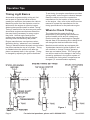
Engine manufacturers use two terms when
describing timing, “advanced” and “retarded”.
Timing is advanced when the spark occurs before
the piston reaches the top of a cylinder. Timing
is retarded when the spark occurs after the
piston has started down in the cylinder. Timing
is changed by adjusting the ignition distributor.
To set timing, the engine manufacturer provides
“timing marks” on the engine’s vibration damper.
Read the vehicle’s manual or contact the
manufacturer for the location of timing marks
on the engine. Also, refer to the vehicle service
manual or contact the manufacturer for the
timing specications for the particular engine.
When to Check Timing
The instant that the spark plug res is
determined by the opening of the distributor
ignition breaker points and will change any
time the point gap or dwell angle is changed.
Normal wear on the breaker point rubbing block
will change the dwell and effect the timing.
Most late model vehicles are equipped with
“breakerless electronic ignition systems” and
will not allow a change in timing, because
there are no breaker points. The Timing Light
can still be used to note changes in the timing
caused by problems in the ignition system or
for resetting the timing when components are
changed (i.e. removed and/or replaced).
Figure 1

Page 5For technical questions, please call 1-800-444-3353.Item 40963
Operating Instructions
Read the ENTIRE IMPORTANT SAFETY INFORMATION section at the
beginning of this document including all text under subheadings therein
before set up or use of this product.
Note: These general instructions will
not apply to all engine designs and/
or vehicles. Consult your engine
manufacturer’s service instructions
which supersede these instructions.
1. Locate the engine’s timing mark
by referring to the vehicle’s
engine manual or contacting the
manufacturer. Refer to the vehicle’s
manual or contact the manufacturer
for the timing specications of
the engine being tested.
2. Start the engine and run for 5-15
minutes until normal operating
temperature is reached.
3. Stop engine.
4. Turn the Timing Advance Knob on
the back of the timing light to 0°.
5. If the vehicle specications and
instructions require it, locate the
vacuum line that attaches to
the ignition distributor vacuum
advance and disconnect the
line and plug the end of it.
A golf tee or small pencil may
be used to plug the line.
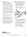
Note: The Spark Plug Clamp is fragile and
may break if dropped or struck sharply.
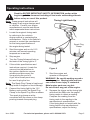
6. Connect the timing light to the 12 V
Battery, and connect the Spark Plug
Clamp to the Spark Plug Wire as shown.
The spark plug clamp must be
connected with the arrow on the clamp
pointing towards the spark plug.
Figure 2
Timing Light Hook Up
Spark Plug
Clamp
#1 Spark
Plug
7. Start the engine and
operate at idle speed.
WARNING! Be careful working around a
running engine. Moving belts and fans
can cause severe injury if contacted.
Metal engine parts are very hot.
Do not contact any part of the engine.
8. Squeeze the trigger on the timing light
and direct the ash onto the engine
timing marks to obtain a reading.
Compare the reading from the
timing mark to the reading in the
manufacturer’s specications.
If the timing does not match with the
timing listed in the manufacturer’s
specications, adjust the timing.

Page 6 For technical questions, please call 1-800-444-3353. Item 40963
Timing Adjustment
1. With the Engine stopped, loosen the
bolt that locks down the distributor,
but do not fully remove it.
It should be loose enough so that you
can rotate the distributor back and forth.
Do not over-loosen the bolt or allow
the distributor to move on its own.
2. Start the engine and run until it reaches
the standard operating temperature.
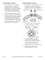
3. Direct the beam from the Timing Light
at the timing marks and slowly rotate
the distributor in very small increments.
Rotate the distributor either right or
left until the timing lines
1
are lined up
(in line with the pointer). See Figure 3.
4. Stop the engine.
5. Tighten the distributor lock down bolt
using care not to change the
position of the distributor.
6. Start the engine and recheck the timing.
If the timing is incorrect, the
distributor may have moved while
bolting it down. Reset the timing.
7. If you have no other tests to perform
with the Timing Light, turn off the
engine and reconnect the vacuum line.
If you have further tests, rst check
to see if the vacuum line needs to
be connected for those tests.
1
Many vehicles have two timing
marks: One at TDC and
another at 10° before TDC.
Testing Centrifugal Advance
1. With the timing light still connected
and the vacuum line still not attached,
speed the engine up slowly to the
manufacturer’s specied speed
for this test (often 2000 RPM)
and watch the timing mark.
2. The timing mark should move steadily,
without jumping. See Figure 3.
Figure 3
Pulley
Timing Marks
Pointer
Max. Advance
Rotation
Degree of Advance
3. If the mark stays stationary or moves
erratically, the Centrifugal Advance (or
other automatic timing advances) should
be repaired by a certied mechanic.
4. Turn the timing advance knob on the
back of the timing light up slowly until
the timing mark moves to TDC or 0.
5. The reading on the timing
advance scale indicates the
amount of centrifugal advance.
Compare with vehicle service manual.

Page 7For technical questions, please call 1-800-444-3353.Item 40963
Testing Vacuum Advance
1. Speed the engine up slowly to the
manufacturer’s specied speed
for this test (often 2000 RPM)
and leave the vacuum line
detached from the distributor.
2. Aim the Timing Light at the timing marks
and turn the timing advance knob on the
back of the timing light up slowly until
the timing mark moves to TDC or 0.
3. Connect the vacuum line
to the distributor.
4. If the timing mark stays still, the
trouble could be a plugged line,
a leaky diaphragm, or a frozen
distributor plate. See a certied
mechanic if the mark doesn’t move.
5. Read the amount of vacuum advance
from the timing marks on the engine.
Compare with vehicle service manual.
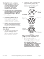
Checking Distributor
Cam Wear
1. This test is done after the timing
has been set and the timing
light lines up with the reference
pointer for cylinder number 1.
2. Connect the Timing Light to the spark
plug wire directly opposite (180º)
from the number 1 cylinder on the
distributor cap. See Figure 4.
#1 Cylinder
Opposite
Cylinder
8 Cylinder
3 1
6 2
5
4
7
8
Opposite
Cylinder
#1 Cylinder
6 Cylinder
16
4
3
2
5
#1 Cylinder
Opposite
Cylinder
4 Cylinder
2
3
1
4
Figure 4
Note: The opposite cylinder is opposite
the #1 Cylinder on Distributor Cap.
3. Start the engine and aim the
Timing Light towards the timing mark.
The reading should be the same as
when the Timing Light was connected
to the number 1 cylinder wire.
If not, the probable cause is a worn out
distributor cam, bushing, or bearing,
or bent distributor shaft. Contact a
qualied service technician for repairs.

Page 8 For technical questions, please call 1-800-444-3353. Item 40963
Small Engine Timing
1. The Timing Light can be used to
test the timing on any combustion
engine that utilizes an impulse or
magneto ignition, such as motorcycles,
lawn mowers, or outboard motors.
If the product does not have a 12 V
battery then use an external battery.
2. Connect a ground from the external
battery’s Negative Post to the engine.
3. Connect the red clip of the Timing light
to the Positive Terminal of the Battery
and the black clip to the Negative
Terminal of the Battery. Connect the
Spark Plug Clamp of the Timing Light
to the spark plug wire with the arrow
pointing towards the spark plug.
Rotary Engine Timing
1. Connect the red and black power leads
to the battery. Connect the Spark
Plug Clamp to the wire for the leading
spark plug on the front rotor housing.
Figure 5
2. Start engine and run it at idle speed.
3. Aim the Timing Light at the timing
indicator pin of the front cover.
Figure 6
LEADINGTRAILING
4. Loosen the distributor locking
nuts and rotate the leading side
distributor body until the timing mark
on the eccentric shaft pulley is in
line with the timing indicator pin.
5. Tighten locking nuts and recheck timing.
6. Repeat this process to set the
trailing side distributor timing.

Page 9For technical questions, please call 1-800-444-3353.Item 40963
Maintenance and Servicing
Procedures not specically
explained in this manual must
be performed only by
a qualied technician.
TO PREVENT SERIOUS INJURY
FROM SHOCK OR FIRE:
Disconnect from the vehicle battery
before performing any inspection,
maintenance, or cleaning procedures.
TO PREVENT SERIOUS INJURY
FROM TOOL FAILURE:
Do not use damaged equipment. If
abnormal noise or vibration occurs, have
the problem corrected before further use.
1. BEFORE EACH USE, inspect general
condition of tool. Check for loose
hardware, misalignment or cracked or
broken parts, damaged electrical wiring,
and any other condition that
may affect its safe operation.
2. AFTER USE, wipe external surfaces
of the tool with clean cloth.
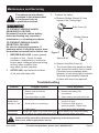
3. To check the Lamp:
a. Remove Rubber Sleeve (3) from
nozzle of the Timing Light.
Rubber Sleeve
(3)
Bulb Cover (4)
Xenon Bulb
Figure 7
b. Remove the Bulb Cover (4).
c. The Xenon Bulb may develop a black
spot around the anode; this is normal.
If the bulb turns completely black
however, a new timing light is needed.
The bulb is permanently soldered
in place and cannot be replaced.
Troubleshooting
Problem Possible Causes Likely Solutions
No ash 1. Switch in “OFF” position.
2. Battery clips connected
backward.
3. Poor connection of clips.
1. Move switch to “ON” position.
2. Reverse the battery clip
connections.
3. Clean battery post and reconnect.
No ash but
double check
indicator is “ON”
1. Spark Plug Clamp ipped backwards.
2. Weak ignition or spark plug.
3. Faulty lamp.
1. Make sure arrow on clamp
points to #1 plug.
2. Connect to other plugs or
spark plug wires. Repair Gap.
3. A new timing light is needed.
Light ashes
intermittently
Timing Light Spark Plug Clamp wire lying
on, or near to, the other spark plug wires.
Route Spark Plug Clamp wire away
from the other spark plug wires.
Follow all safety precautions whenever diagnosing or servicing the tool.
Disconnect power supply before service.

Page 10 For technical questions, please call 1-800-444-3353. Item 40963
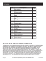
Parts List
Part Description Q’ty
1 Left Housing 1
2 Right Housing 1
3 Rubber Sleeve 1
4 Bulb Cover 1
5 Lens 1
6 Timing Advance Knob 1
7 Nut 1
8 Rear Cover 1
9 Dial Scale 1
10 Tension Meter 1
11 Left Tag 1
12 Right Tag 1
13 Trigger 1
14 Internal Switch 1
15 Board 1
16 Clamp Cable 1
17 Cable Connector 1
18 Screw (M3x10) 5
19 Screw (M3x6) 1
PLEASE READ THE FOLLOWING CAREFULLY
THE MANUFACTURER AND/OR DISTRIBUTOR HAS PROVIDED THE PARTS LIST AND ASSEMBLY
DIAGRAM IN THIS MANUAL AS A REFERENCE TOOL ONLY. NEITHER THE MANUFACTURER
OR DISTRIBUTOR MAKES ANY REPRESENTATION OR WARRANTY OF ANY KIND TO THE
BUYER THAT HE OR SHE IS QUALIFIED TO MAKE ANY REPAIRS TO THE PRODUCT, OR
THAT HE OR SHE IS QUALIFIED TO REPLACE ANY PARTS OF THE PRODUCT. IN FACT, THE
MANUFACTURER AND/OR DISTRIBUTOR EXPRESSLY STATES THAT ALL REPAIRS AND PARTS
REPLACEMENTS SHOULD BE UNDERTAKEN BY CERTIFIED AND LICENSED TECHNICIANS,
AND NOT BY THE BUYER. THE BUYER ASSUMES ALL RISK AND LIABILITY ARISING OUT OF
HIS OR HER REPAIRS TO THE ORIGINAL PRODUCT OR REPLACEMENT PARTS THERETO,
OR ARISING OUT OF HIS OR HER INSTALLATION OF REPLACEMENT PARTS THERETO.

Page 11For technical questions, please call 1-800-444-3353.Item 40963
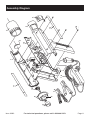
Assembly Diagram
1
2
3
4
5
6
7
8
9
10
11
12
13
14
15
17
18
19
16

Limited 90 Day Warranty
Harbor Freight Tools Co. makes every effort to assure that its products meet high
quality and durability standards, and warrants to the original purchaser that this
product is free from defects in materials and workmanship for the period of 90 days
from the date of purchase. This warranty does not apply to damage due directly or
indirectly, to misuse, abuse, negligence or accidents, repairs or alterations outside
our facilities, criminal activity, improper installation, normal wear and tear, or to lack of
maintenance. We shall in no event be liable for death, injuries to persons or property,
or for incidental, contingent, special or consequential damages arising from the use
of our product. Some states do not allow the exclusion or limitation of incidental or
consequential damages, so the above limitation of exclusion may not apply to you. THIS
WARRANTY IS EXPRESSLY IN LIEU OF ALL OTHER WARRANTIES, EXPRESS OR
IMPLIED, INCLUDING THE WARRANTIES OF MERCHANTABILITY AND FITNESS.
To take advantage of this warranty, the product or part must be returned to us
with transportation charges prepaid. Proof of purchase date and an explanation
of the complaint must accompany the merchandise. If our inspection veries
the defect, we will either repair or replace the product at our election or we may
elect to refund the purchase price if we cannot readily and quickly provide you
with a replacement. We will return repaired products at our expense, but if we
determine there is no defect, or that the defect resulted from causes not within the
scope of our warranty, then you must bear the cost of returning the product.
This warranty gives you specic legal rights and you may also
have other rights which vary from state to state.
Record Serial Number Here:
Note: If product has no serial number, record month and year of purchase instead.
Note: Some parts are listed and shown for illustration purposes only,
and are not available individually as replacement parts.
3491 Mission Oaks Blvd. • PO Box 6009 • Camarillo, CA 93011 • (800) 444-3353
-
 1
1
-
 2
2
-
 3
3
-
 4
4
-
 5
5
-
 6
6
-
 7
7
-
 8
8
-
 9
9
-
 10
10
-
 11
11
-
 12
12


Harbor Freight Tools xenon Advance Timing Light Owner's manual
- Category
- Power tools
- Type
- Owner's manual
- This manual is also suitable for
Ask a question and I''ll find the answer in the document
Finding information in a document is now easier with AI
Related papers
-
Harbor Freight Tools 98475 User manual
-
-
 HFT 60642 Owner's manual
-
Harbor Freight Tools Cylinder Leak_Down Tester User manual
-
-
-
Pittsburgh Automotive Item 60278 Owner's manual
-
-
 Greyhound 65761 User manual
-
 Ship to Shore 99917 User manual


Other documents
-
CEN-TECH 40963 Set Up And Operating Instructions Manual
-
Innova 5568 Owner's manual
-
Chicago Electric 96375 User manual
-
-
-
Actron Inductive Timing Light User manual
-
-
-
Power Fist 8706855 Owner's manual
-