Page is loading ...

X-XX UL
INSTALLATION INSTRUCTIONS
Copyright © 1995 Honeywell Inc. • • All Rights Reserved
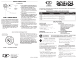
APPLICATION
These Y594G and Y594J combination packs are designed
to meet the specific requirements of Carrier heat pump
equipment. The Y594 packs are designed for 2 stage heat
and 1 stage cool applications. The system switch is SUPL
HT-HEAT-OFF-COOL or SUPL HT-ON-OFF. The fan
switch is AUTO-ON. See Table 1 for model information
and cross reference from Carrier part numbers.
69-0920
TRADELINE
®
Y594
(Multistage Thermostat Subbase)
Package
Table 1. Heat Pump Thermostat/Subbase Combinations.
OS No.
Fig.
No. Contains Replaces Honeywell Replaces Carrier
Changeover
Mode
Y594G1666 7 T874G2004
Q674L1892
Y507J1011 T874G1055
Q674L1041
99TZ90041106 HH07AT171
HH93AZ175
Manual
changeover in
cooling
Y594G1674 6 T874G2004
Q674J1274
Y507J1003 T874G1055
Q674J1035
99TZ90040106 HH07AT171
HH93AZ173
Auto
changeover in
cooling
Y594J1001 5 T874J1069
Q674L1900
— T874J1002
Q674L1074 or
Q674L1637
— HH07AT175
HH93AZ186 or
HH93AZ195
Manual
changeover in
cooling
Y594J1019 4 T874J1069
Q674J1282
— T874J1002
Q674J1068 or
Q674J1159
— HH07AT175
HH93AZ183 or
HH93AZ196
Auto
changeover in
heating
Thermostat Ratings
SWITCHING: sealed mercury switch.
SWITCH RATINGS:
First Stage Heating and Cooling: 6.5A inrush, 1.5A
maximum running at 25 Vac.
Second Stage Heating and Cooling: 1.5A maximum
running at 30 Vac.
Changeover Switch: 6.5A inrush, 1.5A running at 25
Vac.
HEAT ANTICIPATOR:
First Stage Heating and Cooling: fixed voltage type,
1.0A.
Second Stage Heating: adjustable, 0.10 to 1.2A; other
models, fixed voltage type, 1.0A.
TEMPERATURE SETTING RANGE: 42°F to 88°F (6°C to
31°C).
Subbase Ratings
SWITCH RATING: 7.5A inrush, 2.5A running at 30 Vac.
MOUNTING: Designed for mounting on wall or horizontal
outlet box.
OPERATION
The two stages of heat are energized sequentially with
changes in temperature. Stage one comes on first; then if
the temperature at the thermostat continues to move away
from the setpoint, the second stage comes on. The
thermostat is set with about 2°F (1°C) between stages. As
the heating equipment runs and the temperature begins to
move back toward the set point, stage 2 goes off first, then
stage one.
Subbases include an LED (light emitting diode) indicator.
This indicator lights to show that the heat pump cannot
operate and the supplemental heat stage is providing all
heating. This condition can occur in two instances; when
the subbase system switch is set at SUPL. HT. and when
the heat pump compressor has malfunctioned.
The LEDs are not field replaceable.

69-0920
2
Y594 (MULTISTAGE THERMOSTAT SUBBASE) PACKAGE
Mounting and Wiring the Subbase
Disconnect power supply to prevent electrical shock or
equipment damage. All wiring must comply with local
electrical codes and ordinances. Follow equipment
manufacturer wiring instructions when available.
Mount the subbase on a wall or horizontal outlet box. To
mount it on a vertical outlet box, order Honeywell part no.
196393A Cover Plate Assembly, which includes an
adapter ring with two screws for vertical outlet box
mounting and a cover plate to cover marks on the wall.
To install subbase, proceed as follows:
Prepare a hole for the thermostat wires at the
chosen location. Run wires to location.
Pull about 6 in. (152 mm) of wire through the hole.
IMPORTANT
Use 18 gauge, color-coded thermostat cable for
proper wiring.
If mounting the subbase on a vertical outlet box,
install adapter ring with the two screws provided in
the assembly. See Fig. 1.
Pull wire through cover plate, if used, and subbase
wire opening. Secure the cover plate and subbase
with the two screws provided, but do not tighten
down.
Level the subbase using a spirit level. See Fig. 2.
Tighten subbase mounting screws. The subbase
mounting slots provide for minor out-of-level
adjustments.
IMPORTANT
An incorrectly leveled subbase will cause the
temperature control to deviate from setpoint
Connect the system wires to the subbase. See
Fig. 4-7. A letter is stamped near each terminal for
identification. The terminal barrier permits straight or
conventional wraparound wiring connections. See
Fig. 3. Either method is acceptable. Run wires as
close as possible to the subbase, keeping wire
length to a minimum. Push excess wire back into
hole. Plug hole to prevent drafts.
RECYCLING NOTICE
This control contains mercury in a sealed tube.
Do not place control in the trash at the end of its
useful life.
If this control is replacing a control that contains
mercury in a sealed tube, do not place your old
control in the trash.
Contact your local waste management authority for
instructions regarding recycling and the proper
disposal of this control, or of an old control
containing mercury in a sealed tube.
INSTALLATION
When Installing this Product…
Read these instructions carefully. Failure to follow
them could damage the product or cause a hazard-
ous condition.
Check the ratings given in the instructions and on
the product to make sure the product is suitable for
your application.
Installer must be a trained, experienced service
technician.
After installation is complete, check out product
operation as provided in these instructions.
CAUTION
Disconnect power supply to prevent electrical
shock or equipment damage.
Run wires as close as possible to the sub-
base. To prevent interference with the
thermostat linkage, keep wire length to a
minimum. Push excess wire back into the
hole, and plug hole to prevent drafts from
affecting thermostat operation.
Do not overtighten thermostat captive
mounting screws because damage to
subbase threads can result.
Do not short across coil terminals on relay.
This may burn out the heat anticipator.
Never install more than one wire per terminal
unless factory-supplied jumper with spade
terminal is used.
IMPORTANT
Thermostats are calibrated at the factory by using
subbases mounted at true level. Inaccurate sub-
base leveling will cause thermostat control
deviation.
Location
Install the thermostat about 5 ft (1.5m) above the floor in
an area with good air circulation at average room
temperatures.
Do not mount the thermostat where it may be affected by:
— drafts, or dead spots (no air movement) behind doors,
in corners, and above or below shelves.
— hot or cold air from ducts.
— radiant heat from the sun, lights, or appliances.
— concealed pipes and chimneys.
— unheated or uncooled areas such as an outside wall
behind the thermostat.
Mounting the Thermostat
Remove the thermostat cover by pulling the bottom
edge of the cover away from the base until it snaps
free of the retaining posts.
NOTE: The cover is hinged at the top and must be
removed by pulling out at the bottom.
Carefully remove and discard the polystyrene
packing insert that protects the mercury switches
during shipment.
Turn the thermostat over and locate the spring
fingers that engage the subbase contacts. Make
sure the spring fingers are NOT bent flat, preventing
proper electrical contact with the subbase.
Set adjustable heat anticipator indicators, if
provided, as described in Setting the Heat
Anticipator(s) section.

69-0920
3
Y594 (MULTISTAGE THERMOSTAT SUBBASE) PACKAGE
M6009
VERTICAL
OUTLET
BOX
ADAPTER
RING
COVER
PLATE
MOUNTING
SCREWS (2)
1
SUBBASE
SUBBASE
MOUNTING SCREWS (2)
HORIZONTAL
OUTLET
BOX
1
2
2
1 NOT INCLUDED WITH UNIT.
2 ACCESSORY PARTS AVAILABLE (193121A).
THERMOSTAT
CAPTIVE
MOUNTING SCREWS (2)
5
0 6
0
7
0
8
0
5
0
6
0
7
0
8
0
H
E
A
T
C
O
O
L
THERMOSTAT
COVER
50 60 70 80
Fig. 1. Installation of subbases and thermostat on
outlet box.
SPIRIT LEVEL
MOUNTING
HOLES (2)
M927
TOP
MOUNTING
HOLES (2)
WIRING
TERMINAL
THERMOSTAT
CABLE OPENING
TO SPRING FINGER
CONTACTS ON THE
THERMOSTAT
(UP TO 12)
POST (2) FOR
MOUNTING
THERMOSTAT
Fig. 2. Leveling the subbase.
Fig. 3. Wiring connections.
FOR STRAIGHT
INSERTION–
STRIP 5/16 in. (8 mm)
FOR WRAPAROUND–
STRIP 7/16 in. (11 mm)
SUBBASE TERMINAL SCREW
M928
BARRIER
Note the tabs along the top inside edge of the
thermostat base. The tabs fit into the subbase
notches. Mount the thermostat on the subbase and
tighten the captive mounting screws. See Fig. 1. Do
not overtighten captive mounting screws. This can
damage the threads in the subbase.
Place the upper edge of the thermostat cover on the
base and swing cover downward until it engages
retaining posts on base. Tighten the locking cover
screws if assembly is provided.
SETTING
Setting the 2nd Stage (Y594G1666 and
Y594G1674 Only) Heat Anticipator
Set the adjustable heat anticipator to match its primary control
current draw. If the primary control nameplate has no rating or
if further adjustment is necessary, use the following procedure
to measure the current draw of each stage:
Remove thermostat from the subbase. Make sure
the power is on.
Connect an ac ammeter of appropriate range
between the heating terminals of the subbase:
Stage 2: between W2 and R.
Move the system switch to HEAT or ON.
After one minute, read the ammeter and record the
reading.
Remount the thermostat and use a ballpoint pen to
set the adjustable heat anticipator(s) to match the
reading(s) measured in step 4. See Fig. 8.
Temperature Setting
Move the heating and cooling levers to the desired
positions. The minimum differential between heating and
cooling setpoints is 3°F (2°C). Some thermostat models
have nonadjustable lever stops, which set the maximum
heating control point at 68°F or 72°F (20°C or 22°C) and
the minimum cooling control point at 78°F (26°C). Do not
attempt to exceed these limits. Some models have only
one lever for heating and cooling.
Subbase Setting
Available subbase system switch positions vary by
thermostat model. Positions control thermostat operation
as follows:
OFF: Heating and cooling systems are off. If the fan
switch is at the AUTO position, the fan is also off.
HEAT: Heating system is controlled by the thermostat.
Cooling system is off.
COOL: Cooling system is controlled by the thermostat.
Heating system is off.
ON: Thermostat automatically switches between heat
and cool modes, depending on the indoor tempera-
ture.
SUPL. HT.: Supplemental heat is energized. Cooling
system is off. Compressor cannot operate.
Fan switching positions control fan operation as follows:
ON: Fan operates continuously.
AUTO: Fan operates with heat pump and supplemental
heat as controlled by the thermostat.

69-0920
4
Y594 (MULTISTAGE THERMOSTAT SUBBASE) PACKAGE
ON
AUTO
FAN
SUPL.
HEAT
C1
FIELD WIRING CONNECTION
DENOTES CONNECTION POINT BETWEEN SUBBASE AND THERMOSTAT
CO
G
Y
O
R
CO STAGE
L
OFF
ON
H1
C
E
ON
SUPL. HEAT
H2
ON
SUPL. HEAT
X
W2
P
H1
FALL
C1
RISE
CO
H2
FALL
CO
RISE
L1
(HOT)
L2
1
THERMOSTAT SUBBASE
SYSTEM COMPONENTS
COMPRESSOR CONTACTOR
FAN RELAY
HEAT RELAY 1
OUTDOOR
THERMOSTAT
HEAT RELAY
CONTACT 1
HEAT RELAY 2
HEAT RELAY
CONTACT 2
HEAT RELAY 3
"X" RELAY
"P" RELAY
COOL CHANGEOVER
VALVE
SYSTEM
SWITCH
SUPL. HT.
ON
OFF
FAN
SWITCH
AUTO
ON
H1 ANTICIPATOR
H2 ANTICIPATOR
C1 ANTICIPATOR
POWER SUPPLY. PROVIDE DISCONNECT MEANS AND OVERLOAD PROTECTION AS REQUIRED.
1
3
4
5
6
8
9
10
11
O
P
X
E
C
L
G
Y
R
2
W2
SUPL. HT.
LED (RED)
M4563
12
10 8
12
11
9
32
4
6
5
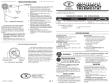
Fig. 4. Y594J1019 Thermostat/Subbase switching and internal connections.

69-0920
5
Y594 (MULTISTAGE THERMOSTAT SUBBASE) PACKAGE
ON
AUTO
FAN
C1
FIELD WIRING CONNECTION
DENOTES CONNECTION POINT BETWEEN SUBBASE AND THERMOSTAT
C0
G
Y
O
R
C0 STAGE
L
OFF
H1
C
E
SUPL. HEAT
H2
SUPL. HEAT
X
W2
HEAT
SUPL.
HEAT
COOL
COOL
HEAT
HEAT
HEAT
P
H1
FALL
C1
RISE
CO
H2
FALL
CO
RISE
L1
(HOT)
L2
1
THERMOSTAT SUBBASE
SYSTEM COMPONENTS
COMPRESSOR CONTACTOR
FAN RELAY
HEAT RELAY 1
OUTDOOR
THERMOSTAT
HEAT RELAY
CONTACT 1
HEAT RELAY 2
HEAT RELAY
CONTACT 2 HEAT RELAY 3
"X" RELAY
"P" RELAY
COOL
CHANGEOVER VALVE
SYSTEM
SWITCH
SUPL. HT.
HEAT
OFF
FAN
SWITCH
AUTO
ON
H1
ANTICIPATOR
H2
ANTICIPATOR
C1 ANTICIPATOR
POWER SUPPLY. PROVIDE DISCONNECT MEANS AND OVERLOAD PROTECTION AS REQUIRED.
1
3
4
5
6
8
9
10
11
O
P
X
E
C
L
G
Y
R
2
W2
SUPL. HT.
LED (RED)
M4564
COOL
12
2
10
8
12
11
9
2
3
6
5
4
Fig. 5. Y594J1001 Thermostat/Subbase switching and internal connections.

69-0920
6
Y594 (MULTISTAGE THERMOSTAT SUBBASE) PACKAGE
ON
AUTO
FAN
C1
FIELD WIRING CONNECTION
DENOTES CONNECTION POINT BETWEEN SUBBASE AND THERMOSTAT
CO
G
Y
O
R
OFF
H1
E
SUPL. HEAT
H2
SUPL. HEAT
L
W2
SUPL. HEAT
ON
ON
ON
C
SUPL. HEAT
8
9
1
6
4
10
H2 ANTICIPATOR
1
SUPL. HT.
LED (RED)
M4565
POWER SUPPLY. PROVIDE DISCONNECT MEANS
AND OVERLOAD PROTECTION AS REQUIRED.
1
SYSTEM COMPONENTSSUBBASETHERMOSTAT
L1
(HOT)
L2
1
H1
FALL
H2
FALL
2
4
6
O
G
R
W
2
E
L
C
Y
CO
RISE
C1
RISE
8
9
10
H1 ANTICIPATOR
C1 ANTICIPATOR
SYSTEM
SWITCH
SUPL. HT.
ON
OFF
FAN
SWITCH
AUTO
ON
FAN RELAY
COOL CHANGEOVER VALVE
OUTDOOR
THERMOSTAT
EM. HT. RELAY 1
EM. HT. RELAY
CONTACT 1
EM. HT. RELAY 2
EM. HT. RELAY
CONTACT 2
EM.HT.
RELAY 3
2
COMPRESSOR
CONTACTOR 1
N.O. SWITCH – INSTALLER ADDED, TO LIGHT EM. HT. LED
WHEN COMPRESSOR OPERATION IS NOT NORMAL.
2
2
Fig. 6. Y594G1674 Thermostat/Subbase switching and internal connections.

69-0920
7
Y594 (MULTISTAGE THERMOSTAT SUBBASE) PACKAGE
ON
AUTO
FAN
C1
FIELD WIRING CONNECTION
DENOTES CONNECTION POINT BETWEEN SUBBASE AND THERMOSTAT
CO
G
Y
O
R
HEAT
H1
E
SUPL. HEAT
H2
SUPL. HEAT
L
W2
SUPL. HEAT
HEAT
HEAT
C
SUPL. HEAT
COOL
OFF
8
9
1
6
4
10
H2 ANTICIPATOR
1
SUPL. HT.
LED (RED)
M4566
POWER SUPPLY. PROVIDE DISCONNECT MEANS
AND OVERLOAD PROTECTION AS REQUIRED.
1
SYSTEM COMPONENTSSUBBASETHERMOSTAT
L1
(HOT)
L2
1
H1
FALL
H2
FALL
2
4
6
O
G
R
W
2
E
L
C
Y
CO
RISE
C1
RISE
8
9
10
H1 ANTICIPATOR
C1 ANTICIPATOR
SYSTEM
SWITCH
SUPL. HT.
COOL
OFF
FAN
SWITCH
AUTO
ON
FAN RELAY
COOL CHANGEOVER VALVE
OUTDOOR
THERMOSTAT
HEAT RELAY 1
HEAT RELAY
CONTACT 1
HEAT RELAY 2
HEAT RELAY
CONTACT 2
HEAT RELAY 3
2
COMPRESSOR
CONTACTOR 1
N.O. SWITCH – INSTALLER ADDED, TO LIGHT EM. HT. LED
WHEN COMPRESSOR OPERATION IS NOT NORMAL.
2
2
COMPRESSOR
FAULT
HEAT
Fig. 7. Y594G1666 Thermostat/Subbase switching and internal connections.

69-0920
8
Y594 (MULTISTAGE THERMOSTAT SUBBASE) PACKAGE
Home and Building Control
Honeywell International, Inc.
1985 Douglas Drive North
Golden Valley, MN 55422
1.2
.4
.6
.3
.2
.15
.12
.1
0
.8
MOVE INDICATOR TO
MATCH CURRENT RATING
OF PRIMARY CONTROL
STAGE TWO
ANTICIPATOR
HEATING CONTROL
M4550
Fig. 8. Adjustable heat anticipator shown.
To switch positions, use thumb and index finger to slide
lever to desired position. Switch lever must stop in detent
directly over the desired function indicator mark for proper
system operation.
CHECKOUT
Heating
Set the system switch on the subbase at HEAT or ON and
the fan switch at AUTO. Move the heating lever on the
thermostat about 10°F (6°C) above room temperature.
Heating (both stages if two-stage thermostat) should start
if there is no time delay or outdoor temperature limiting
system, and the fan should come on. Move the heating
lever about 10°F (6°C) below room temperature. Heating
and fan should shut off.
Cooling
CAUTION
Do not operate cooling if outdoor temperature is
below 50°F (10°C). Refer to manufacturer recom-
mendations.
Set the system switch on the subbase to COOL or ON and
the fan switch to AUTO. Move the cooling lever on the
thermostat about 10°F (6°C) below room temperature.
Cooling and fan should start. Move the cooling lever about
10°F (6°C) above room temperature. Cooling and fan
should stop.
Fan
Set the fan switch to ON. Move the system switch to
different positions; the fan should run continuously. Move
the fan switch to AUTO. Move the system switch to
different positions. Fan operation is controlled with the
heating or cooling system.
LED Indication
Set system switch on subbase at SUPL. HT. The SUPL.
HT. LED should light. Simulate compressor failure and
energize the system. The FAULT LED should light.
CALIBRATION
Thermostat
These thermostats are accurately calibrated at the factory.
They do not
have provision for field calibration
.
Thermometer
The thermometer in your thermostat has been accurately
calibrated at the factory. The thermometer should only
adjustment if it has been dropped or shifted due to
mishandling.
If the setpoint lever and the thermometer reading do not
agree, use the following procedure:
Remove the thermostat cover by pulling up from the
bottom edge of the cover away from the base until it
snaps free of the cover clip.
Set the thermostat cover on a table near an
accurate thermometer.
Allow ten minutes for cover thermometer to sense
area temperature; compare the readings. Be careful
not the touch the thermometer or breathe on it.
If the readings are the same, replace cover and put
the system into operation.
If the readings are different, insert a small screw-
driver in the thermometer slot and turn it until the
thermometers have the same reading. See Fig. 9.
Replace thermostat cover and put the system into
operation.
M5070
Home and Building Control
Honeywell Limited-Honeywell Limitée
35 Dynamic Drive
Scarborough, Ontario
M1V 4Z9
J.H. 5-95 www.honeywell.com/yourhome
Fig. 9. Thermometer calibration.
/