Sanyo VA-94S User manual
- Category
- Security cameras
- Type
- User manual
This manual is also suitable for

VA-94S
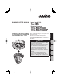
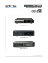
SUMMARY/SETUP MANUAL
Power Board Unit
VCC-MCH5600
VCC-MCH5600P
Megapixel Camera
THIS INSTALLATION SHOULD BE MADE
BY A QUALIFIED SERVICE PERSON AND
SHOULD CONFORM TO ALL LOCAL
CODES.
(Power Boad Unit)
(Megapixel Camera)
EnglishFrançaisEspañolDeutschЁ᭛ㅔԧ
Before installing and using the camera, please read
this manual carefully.
Be sure to keep it handy for later reference.
In addition, be sure to read carefully the electronic
manual (INSTRUCTION MANUAL) contained in the
supplied CD-ROM to ensure correct operation of
the camera.
Important
Be careful when opening holes for installing
the unit. Work with the power and video cables
pulled out for easy installation.
Make sure to properly perform waterproofi ng for
the ceiling where you are installing the unit.
Make sure that the surface in the installation
location has no unevenness and is strong
enough to bear the total weight of the unit.
Install this unit in an environment where the
temperature range stays between –10°C and
+50°C/14°F and 122°F (no condensation
allowed).
As a precaution against static electricity
damage, touch a nearby metal object (door
knob, etc.) to dissipate static electricity in your
body before touching this unit.
•
•
•
•
•

1
Name and Function of Each Component ..................................................................... 2
Installation .................................................................................................................... 3
Connections ................................................................................................................. 5
Control/Address Settings ............................................................................................. 9
Address Settings Table............................................................................................... 10
Network Settings ........................................................................................................ 11
Specifications ............................................................................................................. 12
Copyright Notice ........................................................................................................14
Check your operating environment.
To operate the camera via network operation, you must meet the following operating requirements.
PC
• : IBM PC/AT compatible
Operating system
• : Windows XP Professional/Windows Vista
CPU• : Core2Duo E6700 2.66 GHz or higher
Memory
• : Windows XP: 1GB or more
Windows Vista: 2GB or more
Network interface
• : 10Base-T/100Base-TX (RJ-45 connector)
Display card• : 1920×1200 pixels or higher
Graphics chip
• : ATI RADEON HD2600 series or higher
nVIDIA GeForce 8600 series or higher
nVIDIA Quadro FX550 series or higher
Web browser• : Internet Explorer Ver. 6.0 SP2 or higher,
or Internet Explorer Ver. 7.0
■
You can automatically set up the IP address of the camera.
This software application is useful when two or more cameras are connected to the network.
Download “Auto IP Setup” software application from the supplied CD-ROM.
■
Contents
Accessories
Camera Unit
Surface cover
Drop-prevention cable Clamping core
(VCC-MCH5600)
× 4
(VCC-MCH5600P)
× 5
Power unit
Pattern sheet
Dust sheet Interface board CD-ROM
■
•
•

2
Name and Function of Each Component
This device is composed of a camera unit and power unit (VA-94S).
Connection Point
This is the connection point between the camera unit and the power unit.
Interface Board (accessories)
Control switch (transmission rate and protocol setting, etc.)
Address switch (control camera address setting)
Control terminal (connection of controller and alarm input/output cable)
LAN/EX-HDD Terminal
LAN terminal (RJ-45 type):
Use this socket to connect the camera to your PC to enable network operation.
EX-HDD terminal (USB type):
When recording live video onto an external hard disk, put the hard disk in a dedicated hard disk
case (VA-HDC4000; sold separately) and then connect the case to the camera.
SD Card Slot
When recording live video onto an SD memory card, insert the card into the slot.
Power terminal
Use this cable to connect a 24 VAC power supply.
There is no power indicator on the camera.
Audio output terminal (black: 3.5-mm mini jack)
Connect this jack via an audio cable to the audio input jack of an amplified speaker system or the
monitor.
Audio input terminal (white: 3.5-mm mini jack)
Use this jack to connect an external microphone to listen to the sound while monitoring the live
video, or simultaneously record the video and sound.
Monitor output terminal (BNC type)
This terminal is used for video output. Connect this terminal to a monitor, etc.
By installing an HDMI option board (VA-HDB90; sold separately), the camera can be connected to a
high vision monitor.

3
Installation
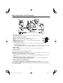
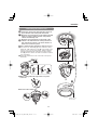
1. Installing the power board unit
Place the supplied pattern sheet on the ceiling,
mark the locations and drill the holes for the cables
and screws.
Pull out the cables from the ceiling.
•
Ceiling
Pattern sheet (Accessory)
Attach the supplied dust sheet (A) to the base of
the power board unit and the detachable piece of
the sheet (B) to the side.
C
AA
BB
When routing cables through side face of power
board unit
AA
■
Pass the cables through the slit (C) in the dust
sheet.
BB
D
CC
Fix the power board unit to the ceiling using
commercially available screws (4 places).
Make sure to tighten the screws properly. Using screws
of sizes other than specified may cause the unit to fall.
Screw size (equivalent to M4/No.8)
Nominal length: 40 mm (1.6 in) or more
Head diameter: ø8.3 mm (0.3 in)
•
•
Connect the cables and set the switches (D).
“Connections” (Page 5), “Control/Address Settings
(Page 9)”

4
Installation
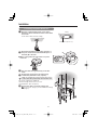
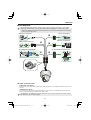
2. Mounting the camera unit
Fasten the camera unit safety wire (E) to the hook
(F) on the inner side of the power board unit.
F
Surface cover
(Accessory)
E
Align the colored dot (blue) on the camera unit with
the arrow on the power board unit, and push the
camera unit until they click.
Align the colored dot (blue) on the inside of the
surface cover with the arrow on the power board
unit, and turn the surface cover in the direction of
the arrow to secure it in place.
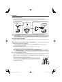
How to attach the drop-prevention cable (accessory)
Peel off the two-sided tape (J) at the end of the cable,
attach the cable end to the hook (K) on the inside of the
surface cover as shown in the figure, and then pull the
cable downward until the small protrusion (L) and the
hook (K) fit in the cable’s first and second holes from the
top, respectively.
Fasten the cable to the hook on the side of the power
board unit.
J
K
L
■
When routing cables through side face of power
board unit
■
To remove the camera unit
Push
Push
■

5
Connections
VCC-MCH5600
Before attempting the following connections, be sure to turn off all components of your system.
Improper connection may cause smoke or failures. Before attempting to connect each system
component, carefully read the instruction manual that comes with it to familiarize yourself with the
correct connection procedure.
•
•
<Monitor Connection>
<Audio Jack Connection>
<Power Connection>
<Control Terminal Connections>
<Network Connection>
<Installing Recording Media>
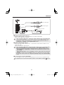
Power Connection
This unit is 24 VAC type. Connect the power cable to the power terminal.
Although the power terminals have no polarity, the earth grounding wire must be connected to the
G (earth terminal) terminal.
To prevent a fire hazard use any UL listed wire rated VW-1.
Be sure to use an 18AWG or thicker wire power cable.
AC-ING
■

6
VCC-MCH5600P
Before attempting the following connections, be sure to turn off all components of your system.
Improper connection may cause smoke or failures. Before attempting to connect each system
component, carefully read the instruction manual that comes with it to familiarize yourself with the
correct connection procedure.
•
•
<Monitor Connection>
<Audio Jack Connection>
<Power Connection>
<Installing Recording Media>
<Network Connection>
<Control Terminal Connections>
Audio Jack Connection
AUDIO OUT Jack (Black)
Connect this jack via an audio cable to the audio input jack of an amplified speaker system or the
monitor.
AUDIO IN Jack (White)
Use this jack to connect an external microphone to listen to the sound while monitoring the live
video, or simultaneously record the video and sound.
This terminal is compatible with a 3.5-mm diameter mono microphone or line mono signals (only the
left channel in cases of stereo signals).
■
Connections

7
Connections
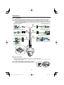
Network Connection
This camera is designed so that you can use all of its functions via network operation.
By connecting the network (LAN) socket of the camera to your PC using a LAN cable, you can
configure and operate it from the Web browser installed on your PC.
Switching hub
Internet connection
LAN connection
PC
PC
Internet
Modem
Router
or
Use a LAN cable no longer than 100 m (109.4 yards) with the shield type CAT5 or higher.
Use a straight-type cable if connecting to LAN, and use a cross-type cable if directly connecting the
camera to a PC.
The supported Web browser is Internet Explorer Ver.6.0 SP2 or higher, or Internet Explorer Ver.7.0.
•
•
•
Installing Recording Media
When recording live video on the camera, install an SD memory card or external hard disk on the
camera.
Always turn the power off when installing a recording medium.
Connecting an External Hard Disk
Put the hard disk in a dedicated hard disk case (VA-HDC4000; sold separately) and then
connect the case to the camera.
Inserting an SD Memory Card
Insert the SD card into the slot until it is locked with a clicking sound.
Push the SD card a bit further into the slot to eject it.
When you insert a new recording medium, format it on the SD/HDD screen.
When you remove the recording medium, first set [SD MEMORY CARD]/[HDD] on the SD/HDD
screen to “NO USE”.
•
•
Control Terminal Connections
Connect the alarm input/output cable and controller to the control terminal of the interface board.
Use a thicker cable than 24AWG for connection. (Maximum length 600 m/656 yards)
Installing and removing the interface board
To place the board back, align the hole (A) at the right corner of the board
to the protruding portion (B) and securely fix the board by depressing it.
To connect alarm or other cables to the interface board, take out the board
by pulling the portion (C).
(C)
(A)
(B)

8
OUT2
OUT1
C
IN8
IN7
IN6
IN5
IN4
IN3
IN2
IN1
COM
485B
485A
WH
B
L
S
L
O
R
B
R
B
K
Y
L
R
D
G
R
L
L
OUT1/2
IN 1-8
COM
COM
Alarm output signal
Alarm input signal
Controller connection
White Yellow
Outputting Alarm Signals (OUT 1-2)
Connect a buzzer, lamp, or other alarm device to the alarm output cable.
Alarm can be output via two channels.
After connecting an alarm device, configure the output conditions for the corresponding alarm
output terminal (ALARM OUT1 or 2) via network operation on the ALARM SETTINGS screen.
Configuration of alarm output terminal is also possible via remote operation. For that, set
[ALARM OUT] to “REMOTE” on the ALARM SETTINGS screen.
•
•
Inputting Alarm Signals (IN 1-8)
Connect an alarm switch, infrared sensor, or other device to detect alarm conditions to the
alarm input cable.
Alarm can be input via eight channels.
After connecting an alarm device, configure the input conditions for the corresponding alarm
input terminal (ALARM IN1 or 2) via network operation on the ALARM SETTINGS screen.
When using the alarm input terminal for day/night switching, configure the following settings.
•
Under [DAY/NIGHT], set [DAY/NIGHT] to “COLOR” and select the terminal you want to use in
[EXT ALARM].
•
On the ALARM SETTINGS screen, in [POLARITY], select the signal polarity of the alarm input
terminal.
Connecting an external switch to ALARM IN1 allows you to set the system clock by operating
the switch. To set the system clock, configure the [CLOCK IN] setting on the CLOCK SETTINGS
screen.
•
•
•
Connecting the Controller (485A/485B)
By connecting a system controller (sold separately), the camera can be controlled remotely.
Configure the protocol, baud rate and address. (Refer to “Control/Address Settings” Page 9.)
Connections

9
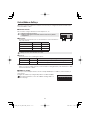
Control/Address Settings
When you connect the camera to a controller, it is necessary to configure the interface board control
switch and address switch.
Control switch
This is used to configure transmission rate and protocol, etc.
Switches 4 and 5 are not used.
Settings in bold typeface in the table below show the factory default
configurations.
•
•
Baud Rate
Configure the transmission rate of connected devices to the transmission
rate of the camera.
Transmission Rate Switch 1 Switch 2
2400 OFF OFF
4800 ON OFF
9600 OFF ON
19200 ON ON
When protocol is set to “PELCO”, set to 2400.
Protocol
Select the protocol for controlling the camera.
Protocol Switch 3 Corresponding Protocol
SSP (SANYO) OFF Automatic switching between Sanyo SSP and high speed SSP
PELCO ON Automatic switching between PELCO-D and PELCO-P
Terminator
When you connect multiple cameras, set the terminator setting (Switch 6) of the final device to “ON”
and all other devices to “OFF”.
Address switch
When you connect multiple cameras, allocate a unique RS485 protocol address (camera number) to
each camera.
ON
12345678
Configure the address by setting the dip switches to “ON” and “OFF”.
For further information, refer to the “Address Settings Table” on
the next page.
■
■
ON
123456
ON
123456

10
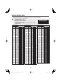
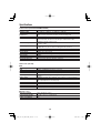
Address Settings Table
In the table, the circle mark “ ” means ON. Set switches as shown in the table.
When protocol is set to ”SSP (SANYO)” :
Available address: 1 – 127
Switch 8 should be set to “OFF”.
When protocol is set to ”PELCO” :
Available address: 1 – 255
When you set the address to 128 – 255, make sure to turn
Switch 8 “ON”.
•
•
•
•
ON
1 2345678
Address (Camera No.)
Switch No.
Protocol
SANYO/PELCO
PELCO 1234567
– 128
1 129
2 130
3 131
4 132
5 133
6 134
7 135
8 136
9 137
10 138
11 139
12 140
13 141
14 142
15 143
16 144
17 145
18 146
19 147
20 148
21 149
22 150
23 151
24 152
25 153
26 154
27 155
28 156
29 157
30 158
31 159
32 160
33 161
34 162
35 163
36 164
37 165
38 166
39 167
40 168
41 169
42 170
Address (Camera No.)
Switch No.
Protocol
SANYO/PELCO
PELCO 1234567
43 171
44 172
45 173
46 174
47 175
48 176
49 177
50 178
51 179
52 180
53 181
54 182
55 183
56 184
57 185
58 186
59 187
60 188
61 189
62 190
63 191
64 192
65 193
66 194
67 195
68 196
69 197
70 198
71 199
72 200
73 201
74 202
75 203
76 204
77 205
78 206
79 207
80 208
81 209
82 210
83 211
84 212
85 213
Address (Camera No.)
Switch No.
Protocol
SANYO/PELCO
PELCO 1234567
86 214
87 215
88 216
89 217
90 218
91 219
92 220
93 221
94 222
95 223
96 224
97 225
98 226
99 227
100 228
101 229
102 230
103 231
104 232
105 233
106 234
107 235
108 236
109 237
110 238
111 239
112 240
113 241
114 242
115 243
116 244
117 245
118 246
119 247
120 248
121 249
122 250
123 251
124 252
125 253
126 254
127 255

11
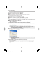
Network Settings
Preparing Your Computer for Network Operation
Check your operating environment. ( Page 1)
Connect the camera to the network to which your PC is also connected.
Configue the network information on your PC.
Configure information such as the IP address of your PC.
Install the “H.264 Plug-in” from the supplied CD-ROM onto your PC.
You are now ready to monitor the surveillance video in the H.264 format.
Start Internet Explorer.
The supported Web browser is Internet Explorer Ver.6.0 SP2 or higher, or Internet Explorer Ver.7.0.
Access the camera from your Web browser.
From your Web browser (Internet Explorer), access the camera and log into the system as an
“admin” user (administrator).
In the address bar, type the IP address of the camera and press [Enter] key.
When you access the camera, the login screen appears.
If this is the first access to the camera, in the Address bar, enter the default IP address as follows.
If you set [SSL] to “ON”, before the IP address, type “https://” (instead of “http://”).
Attempts to access the camera using the default IP address will fail if that address is already
being used by another device in the network.
If so, change the IP address of the existing device before accessing the camera.
Type your user name and password and click [OK].
The language selection screen appears.
If this is the first access to the camera, log in as an admin user (administrator) using the following
default authentication information.
User name: admin
Password: admin
•
•
Click the button corresponding to the language you want to use.
The live screen appears.
From the second login onwards, the live screen appears automatically by skipping the language
selection screen.
If this is the first access to the camera, configure the system clock on the CLOCK SETTINGS
screen.

12
Specifications
Camera Unit (VCC-MCH5600/MCH5600P)
Image pickup device 1/2.5” CMOS sensor
Effective pixels 16:9 1920 (H) × 1080 (V), 4:3 1600 (H) × 1200 (V)
Lowest image
illumination
50IRE: 2.0 lx (F1.8, in color mode with high gain)
50IRE: 0.1 lx (F1.8 in black-and-white mode with high gain)
Video S/N ratio 50 dB or higher (when AGC is ‘Off’)
Lens Focal Length: 6.3 to 63 mm, F number: F1.8 - 2.5
Optical zoom 10x, electronic zoom 16x (up to 160x when used in
combination with the optical zoom)
Rotational scope Pan: 360° endless pan
Tilt: –20 to +200°
Rotation speed Pan: Max 420°/sec
Tilt: Max 360°/sec (0.1 to 120°/sec during manual operation)
Preset position Max 255
Auto mode Sequential, auto pan, tour, automatic return
Privacy mask ON/OFF, up to 32 positions
Motion sensor ON (detection area setting, video analytics)/OFF, face detection function
Auto pursuit ON/OFF
Sway compensation ON/OFF
Language selection English, French, German, Spanish, Japanese
For further details on the specifications of the camera, refer to the electronic manual.
Power unit (VA-94S)
I/O■
Video output Monitor output terminal (BNC)
LAN 10BASE-T/100BASE-TX (RJ-45 connector)
EX-HDD Connector For connecting SANYO-specified external hard disk case (VA-HDC4000)
SD Card Slot 1 (SDHC compliant, max. 32 GB supported)
Alarm input 8 (NO/NC), also serving as Day/Night switching terminal <control
terminal>
Alarm output 2 (NO/NC switching, 16 V, 150 mA, open collector) <control terminal>
Audio input/output Audio input (white: 3.5-mm mini jack)
Audio output (black: 3.5-mm mini jack)
Communication method RS-485
Protocol SSP, PELCO-D
Baud rate 2400, 4800, 9600, 19200
Address 1 - 255 (Sanyo SSP: 1 - 127)
HDMI output: Possible when an HDMI option board (VA-HDB90; sold separately) is attached
•
Power source■
Operating ambient
temperature/humidity
–10 to +50°C/14 to 122°F
90% RH or less (no condensation)
Power source 24 VAC±10%, 50/60 Hz
Power consumption 29 W

13
Recording media ■
SD memory card/
External HDD
Normal recording, alarm recording, backup video recording in event of
a network failure, log information
For the recommended SD memory cards, visit our website.
http://www.sanyo-cctv.net/
Network■
Image/video compression H.264/JPEG
Video size (H.264) (16:9) 1920×1080, 1280×720, 640×360, 320×180
(4:3) 1600×1200, 1280×960, 1024×768, 640×480, 320×240
Video size (JPEG) (16:9) 1920×1080, 1280×720, 1024×576, 640×360
(4:3) 1600×1200, 1280×960, 1024×768, 800×600, 640×480, 320×240
Picture quality QUALITY mode: BASIC, NORMAL, ENHANCED, FINE, SUPER FINE
BITRATE mode: User-specified bit rate
Interface 10BASE-T/100BASE-TX
Protocol TCP/IP, UDP, HTTP, HTTPS, SMTP, NTP, DHCP, FTP, DDNS, RTP,
RTSP, RTCP
Audio G.711 (Bidirectional)
Simultaneous access 20
Security
BASIC authentication (ID/password), SSL, IP filtering
Dimensions/Weight
192 (7.56)
103 (4.06) 78 (3.07)
145 (5.71)
38.5
(1.52)
54 (2.12)
Camera unit:
approx. 1.3 kg/45.9 oz.
Power unit:
approx. 450 g/15.9 oz.
Surface cover:
approx. 110 g/3.9 oz
Unit: mm (inch)
Appearance and specifications are subject to change without prior notice or obligations.
■
Specifications

14
Copyright Notice
The instruction manual and the software are copyrighted by SANYO Electric Co., Ltd. No materials
contained in the manual and the software may, wholly or partially, be copied, modified, reproduced, or
distributed in any format without the prior permission of the copyright holder.
Microsoft, Windows, ActiveX and Internet Explorer are registered trademarks or trademarks of
Microsoft Corporation in the United States and other countries.
The official name for “Windows” used in this manual is Microsoft
®
Windows
®
Operating System.
In this manual, note that the word “Windows” refers to both “Microsoft
®
Windows
®
XP Operating
System” and “Microsoft
®
Windows
®
Vista Operating System”.
Intel and Pentium are registered trademarks or trademarks of Intel Corporation and its subsidiaries in
the United States and other countries.
IBM and IBM PC/AT are trademarks of International Business Machines Corporation.
All other brands and product names in this manual are the registered trademarks or trademarks of
their respective owners.
SDHC Logo is a trademark.
Notes on data storage
It is recommended that important data be copied to a separate medium.
In the following situations, it is possible that recorded data may be lost (destroyed). Our company
bears absolutely no responsibility for damages or profi ts loss due to the loss of data.
• The medium (SD card or external hard disk) is not used correctly.
• The medium is not installed on the device correctly.
• The medium is subjected to electrical or mechanical shock.
• The card is removed or the power is turned off while the card is being accessed.
• The medium has reached the end of its service life.
License for Software Contained in CD-ROM
Please read carefully the terms and conditions contained in the license agreement that appears
on the screen during the software installation process. Provided that you have agreed to all the
terms and conditions therein, you may use the software subject to the license agreement.
For information on the other products or services provided by third parties which are introduced in
the CD-ROM, please contact each supplier or manufacturer.
■
•
•
■
•
•

SANYO Electric Co., Ltd.
1AC6P1P4031--
L9EBQ/WA, L5DD2/XE, US (1009KR)
SUMMARY/SETUP MANUAL Power Board Unit: VA-94S Megapixel Camera: VCC-MCH5600/MCH5600P
-
 1
1
-
 2
2
-
 3
3
-
 4
4
-
 5
5
-
 6
6
-
 7
7
-
 8
8
-
 9
9
-
 10
10
-
 11
11
-
 12
12
-
 13
13
-
 14
14
-
 15
15
-
 16
16


Sanyo VA-94S User manual
- Category
- Security cameras
- Type
- User manual
- This manual is also suitable for
Ask a question and I''ll find the answer in the document
Finding information in a document is now easier with AI
Related papers
-
Sanyo VCC-HD5600 Series User manual
-
-
Sanyo MEGAPIXEL VCC-HD5400P User manual
-
-
-
-
Sanyo VCC-P7575PA User manual
-
-
-
Other documents
-
 Santec SanStore 8/16HMX User manual
-
Pelco PelcoNet NET4001A User manual
-
-
DSE RH-BCC1 User manual
-
-
-
Messoa NVR208-025 User manual
-
 United Digital Technologies KCM-7311 Datasheet
-
i3 International Annexxus 516 Encoder User manual
-
Hikvision DS-9564NIRT User manual

