
COPYRIGHT © NOVEMBER, 2014 BY GRIZZLY INDUSTRIAL, INC., REVISED MAY, 2014 (TS)
WARNING: NO PORTION OF THIS MANUAL MAY BE REPRODUCED IN ANY SHAPE
OR FORM WITHOUT THE WRITTEN APPROVAL OF GRIZZLY INDUSTRIAL, INC.
#TS14577 PRINTED IN TAIWAN
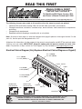
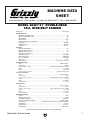
The following changes were made to this machine since the owner's manual was printed:
• Obtained CSA certification meeting CSA C22.2 #105-1953 and UL 987-7th standards.
• Changed transformer, contactors, overload relays, terminal blocks, 440V conversion kit components,
and wiring.
• Changed circuit requirements.
• Replaced oscillation diaphragm assembly with an air cylinder.
Note: At the top of each page is a note that indicates which page it replaces in the original manual. On the
parts list, the new parts are designated with a “V2”.
Aside from this information, all other content in the owner's manual applies and MUST be read and under-
stood for your own safety. IMPORTANT: Keep this update with the owner's manual for future refer-
ence. For questions or help, contact our Tech Support at (570) 546-9663 or [email protected].
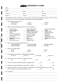
Electrical Cabinet Diagram (Only Replaces Electrical Cabinet Diagram on Page 64)
READ THIS FIRST
For questions or help with this product contact Tech Support at (570) 546-9663 or techsupport@grizzly.com
Models G0486 & G0487
***IMPORTANT UPDATE***
For Machines Mfd. Since January, 2014
and Owner's Manual Printed April, 2006
113V2
113V2-1
110V2
116-1V2
116-2V2
118-1V2
118-2V2
112 (G0486)
112V3 (G0487)
111-3V2 (G0486)
111-3 (G0487)
114
111-1 (G0486)
111-1V2 (G0487)
111-2 (G0486)
111-2V2 (G0487)
139-1
139
G0486 440V
Conversion Kit
G0487 440V
Conversion Kit
139-2
139-1V2
139V2
139-2

-2-
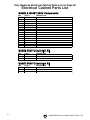
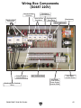
G0486/G0487 Manual Update (Mfd. Since 1/14)
Electrical Cabinet Parts List
Only Replaces Electrical Cabinet Parts List on Page 65
G0486 & G0487 220V Components
REF PART # DESCRIPTION
110V2 P04868110V2 TRANSFORMER SUENN LIANG SP-TBS-20250 V2.10.11
111-1 P04868111-1 CONTACTOR SCHN LC1D38 220V
111-1V2 P04878111-1V2 CONTACTOR SCHN LC1D40A 220V V2.10.11
111-2 P04868111-2 CONTACTOR SCHN LC1D38 220V
111-2V2 P04878111-1V2 CONTACTOR SCHN LC1D40A 220V V2.10.11
111-3V2 P04868111-3V2 CONTACTOR SCHN LC1D25 220V V2.10.11
111-3 P04878111-3 CONTACTOR SCHN LC1D38 220V
112 P04868112 OL RELAY SCHN LR3D35 30-38A
112V3 P0539012V3 OL RELAY SCHN LRD340 30-40A V3.04.13
113V2 P04868113V2 FUSE CB KTK-4 10 X 38 550V 4A
113V2-1 P04868113V2-1 FUSE HOLDER SE DF101 10 X 38 V2.10.11
114 P05818114 OL RELAY SCHN LR3D12 5.5-8A
116-1V2 P04868116-1V2 TERMINAL PLATE ENTRELEC M16/12P YL/GRN V2.10.11
116-2V2 P04868116-2V2 TERMINAL PLATE ENTRELEC M16/12 GRAY V2.10.11
118-1V2 P04868118-1V2 TERMINAL PLATE ENTRELEC M4/6 GRAY V2.10.11
118-2V2 P04868118-2V2 TERMINAL PLATE ENTRELEC M4/6P YL/GRN V2.10.11
G0486 440V Conversion Kit
REF PART # DESCRIPTION
139 P04868139 440V CONVERSION KIT
139-1 PH29348134 OL RELAY SCHN LR3D21 12-18A
139-2 P04868139-2 OL RELAY SCHN LR3D08 2.5-4A
G0487 440V Conversion Kit
REF PART # DESCRIPTION
139V2 P04878139V2 440V CONVERSION KIT V2.10.11
139-1V2 P99809139A-1V2 OL RELAY SCHN LR3D325 17-25A V2.09.10
139-2 P04868139-2 OL RELAY SCHN LR3D08 2.5-4A

-3-
G0486/G0487 Manual Update (Mfd. Since 1/14)
Replaces Page 8
ELECTRICAL EQUIPMENT INJURY RISKS. You
can be shocked, burned, or killed by touching live
electrical components or improperly grounded
machinery. To reduce this risk, only allow qualified
service personnel to do electrical installation or
repair work, and always disconnect power before
accessing or exposing electrical equipment.
DISCONNECT POWER FIRST.
Always discon-
nect machine from power supply BEFORE making
adjustments, changing tooling, or servicing machine.
This prevents an injury risk from unintended startup
or contact with live electrical components.
EYE PROTECTION. Always wear ANSI-approved
safety glasses or a face shield when operating or
observing machinery to reduce the risk of eye
injury or blindness from flying particles. Everyday
eyeglasses are NOT approved safety glasses.
OWNER’S MANUAL. Read and understand this
owner’s manual BEFORE using machine.
TRAINED OPERATORS ONLY. Untrained oper-
ators have a higher risk of being hurt or killed.
Only allow trained/supervised people to use this
machine. When machine is not being used, dis-
connect power, remove switch keys, or lock-out
machine to prevent unauthorized use—especially
around children. Make workshop kid proof!
DANGEROUS ENVIRONMENTS. Do not use
machinery in areas that are wet, cluttered, or have
poor lighting. Operating machinery in these areas
greatly increases the risk of accidents and injury.
MENTAL ALERTNESS REQUIRED. Full mental
alertness is required for safe operation of machin-
ery. Never operate under the influence of drugs or
alcohol, when tired, or when distracted.
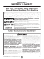
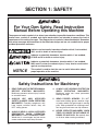
For Your Own Safety, Read Instruction
Manual Before Operating This Machine
The purpose of safety symbols is to attract your attention to possible hazardous conditions.
This manual uses a series of symbols and signal words intended to convey the level of impor-
tance of the safety messages. The progression of symbols is described below. Remember that
safety messages by themselves do not eliminate danger and are not a substitute for proper
accident prevention measures. Always use common sense and good judgment.
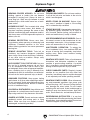
Indicates a potentially hazardous situation which, if not avoided,
MAY result in minor or moderate injury. It may also be used to alert
against unsafe practices.
Indicates a potentially hazardous situation which, if not avoided,
COULD result in death or serious injury.
Indicates an imminently hazardous situation which, if not avoided,
WILL result in death or serious injury.
This symbol is used to alert the user to useful information about
proper operation of the machine.
NOTICE
Safety Instructions for Machinery
SECTION 1: SAFETY

-4-
G0486/G0487 Manual Update (Mfd. Since 1/14)
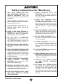
WEARING PROPER APPAREL. Do not wear
clothing, apparel or jewelry that can become
entangled in moving parts. Always tie back or
cover long hair. Wear non-slip footwear to avoid
accidental slips, which could cause loss of work-
piece control.
HAZARDOUS DUST. Dust created while using
machinery may cause cancer, birth defects, or
long-term respiratory damage. Be aware of dust
hazards associated with each workpiece material,
and always wear a NIOSH-approved respirator to
reduce your risk.
HEARING PROTECTION. Always wear hear-
ing protection when operating or observing loud
machinery. Extended exposure to this noise
without hearing protection can cause permanent
hearing loss.
REMOVE ADJUSTING TOOLS. Tools left on
machinery can become dangerous projectiles
upon startup. Never leave chuck keys, wrenches,
or any other tools on machine. Always verify
removal before starting!
USE CORRECT TOOL FOR THE JOB. Only use
this tool for its intended purpose—do not force
it or an attachment to do a job for which it was
not designed. Never make unapproved modifica-
tions—modifying tool or using it differently than
intended may result in malfunction or mechanical
failure that can lead to personal injury or death!
AWKWARD POSITIONS. Keep proper footing
and balance at all times when operating machine.
Do not overreach! Avoid awkward hand positions
that make workpiece control difficult or increase
the risk of accidental injury.
CHILDREN & BYSTANDERS. Keep children and
bystanders at a safe distance from the work area.
Stop using machine if they become a distraction.
GUARDS & COVERS. Guards and covers reduce
accidental contact with moving parts or flying
debris. Make sure they are properly installed,
undamaged, and working correctly.
FORCING MACHINERY. Do not force machine.
It will do the job safer and better at the rate for
which it was designed.
NEVER STAND ON MACHINE. Serious injury
may occur if machine is tipped or if the cutting
tool is unintentionally contacted.
STABLE MACHINE. Unexpected movement dur-
ing operation greatly increases risk of injury or
loss of control. Before starting, verify machine is
stable and mobile base (if used) is locked.
USE RECOMMENDED ACCESSORIES. Consult
this owner’s manual or the manufacturer for rec-
ommended accessories. Using improper acces-
sories will increase the risk of serious injury.
UNATTENDED OPERATION. To reduce the
risk of accidental injury, turn machine OFF and
ensure all moving parts completely stop before
walking away. Never leave machine running
while unattended.
MAINTAIN WITH CARE. Follow all maintenance
instructions and lubrication schedules to keep
machine in good working condition. A machine
that is improperly maintained could malfunction,
leading to serious personal injury or death.
CHECK DAMAGED PARTS. Regularly inspect
machine for any condition that may affect safe
operation. Immediately repair or replace damaged
or mis-adjusted parts before operating machine.
MAINTAIN POWER CORDS. When disconnect-
ing cord-connected machines from power, grab
and pull the plug—NOT the cord. Pulling the cord
may damage the wires inside. Do not handle
cord/plug with wet hands. Avoid cord damage by
keeping it away from heated surfaces, high traffic
areas, harsh chemicals, and wet/damp locations.
EXPERIENCING DIFFICULTIES. If at any time
you experience difficulties performing the intend-
ed operation, stop using the machine! Contact our
Technical Support at (570) 546-9663.
Replaces Page 9

-5-
G0486/G0487 Manual Update (Mfd. Since 1/14)
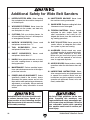
Replaces Page 10
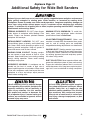
Additional Safety for Wide Belt Sanders
MINIMUM STOCK DIMENSION. To avoid kick-
back, never sand workpieces below minimum
specifications listed in Data Sheet.
ADJUSTMENTS/MAINTENANCE. Make sure
machine is turned OFF, disconnected from power
and air, and all moving parts are completely
stopped before doing adjustments or maintenance.
SANDING DUST. Sanding creates large amounts
of dust and flying chips that can lead to eye injury
or respiratory illness. Reduce risk of these hazards
by wearing approved eye and respiratory protec-
tion when using sander.
DUST COLLECTION. Never operate without ade-
quate dust collection system in place and running.
Proper dust collection reduces dust in work area,
which decreases risk of long-term respiratory dam-
age, but it is not a substitute for using a respirator.
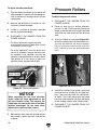
Serious injury or death can occur from hands getting trapped between workpiece and conveyor
table, getting entangled in rotating parts inside machine, or lacerated by sanding drum.
Workpieces thrown by sander can strike nearby operators. Long-term respiratory damage can
occur from using sander without proper use of a respirator and an adequate dust collection
system. To minimize risk of getting hurt or killed, anyone operating machine MUST completely
heed hazards and warnings below.
FEEDING WORKPIECE. DO NOT place fingers
under bottom of workpiece while feeding it into
sander. Fingers can become pinched between
workpiece and conveyor.
ENTANGLEMENT HAZARDS. DO NOT wear
loose clothing, gloves, or jewelry, and tie back long
hair. Never reach inside operating machine or try
clearing jammed workpiece. Keep all guards in
place and secure, and all doors closed.
SANDING DRUM CONTACT. Rotating sandpa-
per can remove a large amount of flesh in a few
seconds. Keep hands away from rotating sanding
drum(s) during operation. Never touch moving
sandpaper on purpose.
WORKPIECE KICKBACK. A workpiece can be
ejected out the front of sander at high rate of
speed, and hit operator or bystanders. Never stand
in-line with workpiece, never feed more than one
workpiece at a time, and always adjust pressure
rollers below sanding roller.
No list of safety guidelines can be complete.
Every shop environment is different. Always
consider safety first, as it applies to your
individual working conditions. Use this and
other machinery with caution and respect.
Failure to do so could result in serious per-
sonal injury, damage to equipment, or poor
work results.
Like all machinery there is potential danger
when operating this machine. Accidents are
frequently caused by lack of familiarity or
failure to pay attention. Use this machine
with respect and caution to decrease the
risk of operator injury. If normal safety pre-
cautions are overlooked or ignored, serious
personal injury may occur.

-6-
G0486/G0487 Manual Update (Mfd. Since 1/14)
Replaces Page 11
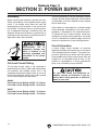
SECTION 2: POWER SUPPLY
Availability
Before installing the machine, consider the avail-
ability and proximity of the required power supply
circuit. If an existing circuit does not meet the
requirements for this machine, a new circuit must
be installed. To minimize the risk of electrocution,
fire, or equipment damage, installation work and
electrical wiring must be done by an electrican or
qualified service personnel in accordance with all
applicable codes and standards.
Electrocution, fire, or
equipment damage may
occur if machine is not
correctly grounded and
connected to the power
supply.
Full-Load Current Rating
The full-load current rating is the amperage a
machine draws at 100% of the rated output power.
On machines with multiple motors, this is the
amperage drawn by the largest motor or sum of all
motors and electrical devices that might operate
at one time during normal operations.
The full-load current is not the maximum amount
of amps that the machine will draw. If the machine
is overloaded, it will draw additional amps beyond
the full-load rating.
If the machine is overloaded for a sufficient length
of time, damage, overheating, or fire may result—
especially if connected to an undersized circuit.
To reduce the risk of these hazards, avoid over-
loading the machine during operation and make
sure it is connected to a power supply circuit that
meets the requirements in the following section.
For your own safety and protection of
property, consult an electrician if you are
unsure about wiring practices or electrical
codes in your area.
A power supply circuit includes all electrical
equipment between the breaker box or fuse panel
in the building and the machine. The power sup-
ply circuit used for this machine must be sized to
safely handle the full-load current drawn from the
machine for an extended period of time. (If this
machine is connected to a circuit protected by
fuses, use a time delay fuse marked D.)
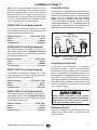
Circuit Information
G0486:
Full-Load Current Rating at 220V .. 61.2 Amps
Full-Load Current Rating at 440V .. 30.6 Amps
G0487:
Full-Load Current Rating at 220V .. 75.2 Amps
Full-Load Current Rating at 440V .. 37.6 Amps

-7-
G0486/G0487 Manual Update (Mfd. Since 1/14)
In Addition to Page 11
G0486 220V Circuit Requirements
Nominal Voltage ................... 220V, 230V, 240V
Cycle ..........................................................60 Hz
Phase .................................................... 3-Phase
Circuit Rating ...................................... 80 Amps
G0486 440V Circuit Requirements
Nominal Voltage ............................. 440V, 480V
Cycle ..........................................................60 Hz
Phase .................................................... 3-Phase
Circuit Rating ...................................... 40 Amps
Note: The circuit requirements listed in this man-
ual apply to a dedicated circuit—where only one
machine will be running at a time. If this machine
will be connected to a shared circuit where mul-
tiple machines will be running at the same time,
consult a qualified electrician to ensure that the
circuit is properly sized for safe operation.
G0487 220V Circuit Requirements
Nominal Voltage ................... 220V, 230V, 240V
Cycle ..........................................................60 Hz
Phase .................................................... 3-Phase
Circuit Rating .................................... 100 Amps
G0487 440V Circuit Requirements
Nominal Voltage ............................. 440V, 480V
Cycle ..........................................................60 Hz
Phase .................................................... 3-Phase
Circuit Rating ...................................... 50 Amps
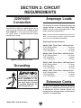
Connection Type
Figure 1. Typical setup of a permanently
connected machine.
Power
Source
Locking
Disconnect Switch
Machine
Ground
Ground
ConduitConduit
A permanently connected (hardwired) power sup-
ply is typically installed with wires running through
mounted and secured conduit. A disconnecting
means, such as a locking switch (see following
Figure
), must be provided to allow the machine
to be disconnected (isolated) from the power
supply when required. This installation must be
performed by an electrician in accordance with all
applicable electrical codes and ordinances.
Extension Cords
Since this machine must be permanently con-
nected to the power supply, an extension cord
cannot be used.
Serious injury could occur if you connect
the machine to power before completing the
setup process. DO NOT connect to power
until instructed later in this manual.
Grounding Instructions
In the event of a malfunction or breakdown,
grounding provides a path of least resistance
for electrical current to reduce the risk of electric
shock. A permanently connected machine must
be connected to a grounded metal permanent wir-
ing system; or to a system having an equipment-
grounding conductor. All grounds must be verified
and rated for the electrical requirements of the
machine. Improper grounding can increase the
risk of electric shock!
This machine is prewired to operate on a 220V
power supply circuit that has a verified ground and
meets the following requirements:
This machine is prewired to operate on a 220V
power supply circuit that has a verified ground and
meets the following requirements:
This machine can be converted to operate on a
440V power supply (refer to Voltage Conversion
instructions) that has a verified ground and meets
the following requirements:
This machine can be converted to operate on a
440V power supply (refer to Voltage Conversion
instructions) that has a verified ground and meets
the following requirements:

-8-
G0486/G0487 Manual Update (Mfd. Since 1/14)
Replaces Page 12
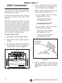
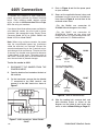
440V Conversion
Figure 7. 440V transformer connection.
Transformer
1
2
3
0
440 2000 0 220
Sanding Motor
Thermal
Overload Relay
Conveyor Motor
Thermal Overload Relay
Figure 8. Location of 440V conversion
components.
To connect this machine to 440V three-phase,
you must purchase a 440V Conversion Kit. Each
machine requires a unique kit.
If you do not have three-phase power available for
your wide belt sander, you must install a phase
converter.
Note: When using a phase converter, the power
from the manufactured power leg (sometimes
called the wild wire) can fluctuate. Connect the
manufactured power leg to the S terminal to pre-
vent damage to the transformer. The wire from the
S terminal can handle some fluctuation because
it goes directly to the motor. The power going to
the R and T terminals goes to the transformer and
must be consistent to prevent damage.
To convert sander to 440V:
1. DISCONNECT SANDER FROM POWER!
2. Open electrical cabinet located on back of
machine.
3. On transformer, remove wire connected to
the far right 220V terminal, and re-connect it
to 440V terminal, as shown in Figure 7.
4. Swap out sanding and conveyor motor ther-
mal overload relays from the 440V conver-
sion kit at locations shown in Figure 8.
Note: To order a 440V conversion kit, contact
Customer Service at (800) 523-4777.
— For the G0486, order Part Number
P04868139, which includes:
Sanding Motor Relay LR3D21
(Set amperage dial to 17A)
Conveyor Motor Relay LR3D08
(Set amperage dial to 3A)
— For the G0487, order Part Number
P04878139V2, which includes:
Sanding Motor Relay LR3D325
(Set amperage dial to 18A)
Conveyor Motor Relay LR3D08
(Set amperage dial to 3A)
5. Wire the sanding belt, conveyor belt, and
table elevation motors as shown on Motor
Wiring diagrams on Page 47 of your Owner's
Manual.

-9-
G0486/G0487 Manual Update (Mfd. Since 1/14)
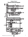
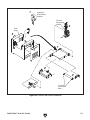
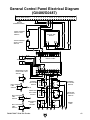
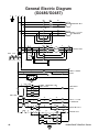
General Wiring Diagram
Replaces Page 41

-10-
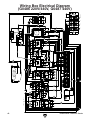
G0486/G0487 Manual Update (Mfd. Since 1/14)
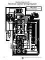
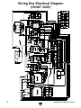
Replaces Pages 42 & 44
Electrical Cabinet Wiring Diagram
NOTICE
To rewire for 440V operation, refer to
440V Conversion on Page 8.

-11-
G0486/G0487 Manual Update (Mfd. Since 1/14)
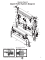
Replaces Page 60
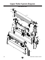
Upper Roller System Diagram
Previous Version Air Cylinder
New Version Air Cylinder
(Part No 321V2)
101
101-1
102
102-1
103
110
103-1
104
104-1
105
106
107
108
108
108
108
109
111
111
112
113
114
115
115
115-1
116
115-1
117
118
119
120
121
122
204
123
124
125
126
127
128
129
130
130
131
131
132
132
133
134
135
136
137
138
140
142
201
202
202
203
203
205
206
207
204
205
208
208
301
302
303
304
304
305
310
320
323
306
131
141
321V2
322

-12-
G0486/G0487 Manual Update (Mfd. Since 1/14)
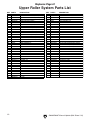
Upper Roller System Parts List
Replaces Page 61
REF PART # DESCRIPTION REF PART # DESCRIPTION
101 P04866101 SQUARE FRAME REAR (G0486) 126 P04866126 ALUMINUM PLATE
101 P04876101 SQUARE FRAME REAR (G0487) 127 PS02M PHLP HD SCR M4-.7 X 12
101-1 P04866101-1 SQUARE FRAME FRONT (G0486) 128 P04866128 SHUTDOWN BRACKET
101-1 P04876101-1 SQUARE FRAME FRONT (G0487) 129 PN11 HEX NUT 3/8-24
102 P04866102 REAR BRACKET (G0486) 130 PW07 FLAT WASHER 5/16
102 P04876102 REAR BRACKET (G0487) 131 PLW01 LOCK WASHER 5/16
102-1 P04866102-1 FRONT BRACKET (G0486) 132 PB09 HEX BOLT 5/16-18 X 1/2
102-1 P04876102-1 FRONT BRACKET (G0487) 133 PS08 PHLP HD SCR 10-24 X 3/4
103 P04866103 FRAME SEAL RIGHT (G0486) 134 PN07 HEX NUT 10-24
103 P04876103 FRAME SEAL RIGHT (G0487) 135 P04866135 CONNECTOR OF OIL CAP
103-1 P04866103-1 FRAME SEAL FRNT RIGHT (G0486) 136 P04866136 SHAFT OF OIL CAP
103-1 P04876103-1 FRAME SEAL FRNT RIGHT (G0487) 137 PSB76 CAP SCREW 1/2-12 X 1-1/2
104 P04866104 FRAME SEAL LEFT (G0486) 138 PB53 HEX BOLT 1/2-12 X 1
104 P04876104 FRAME SEAL LEFT (G0487) 140 PFH25M FLAT HD SCR M4-.7 X 12
104-1 P04866104-1 FRAME SEAL FRNT LEFT (G0486) 141 PN02 HEX NUT 5/16-18
104-1 P04876104-1 FRAME SEAL FRNT LEFT (G0487) 142 P04866142 O-RING
105 PFH03 FLAT HD SCR 1/4-20 X 1/2 201 P04866201 UPPER ROLLER BRACKET (G0486)
106 PLW04 LOCK WASHER 3/8 201 P04876201 UPPER ROLLER BRACKET (G0487)
107 PB18 HEX BOLT 3/8-16 X 1 202 P05816202 UPPER ROLLER (G0486)
108 PLW07 LOCK WASHER 1/2 202 P04876202 UPPER ROLLER (G0487)
109 PB40 HEX BOLT 1/2-12 X 1-1/4 203 P04866203 UPPER ROLLER BRACKET
110 PS04 PHLP HD SCR 1/4-20 X 1/2 204 P05275104 CYL. CARTRIDGE BEARING UCC205
111 PSB07 CAP SCREW 5/16-18 X 3/4 205 PSS02M SET SCREW M6-1 X 6
112 PB03 HEX BOLT 5/16-18 X 1 206 PSB16 CAP SCREW 3/8-16 X 3/4
113 P04866113 AIR CYLINDER 207 PLW04 LOCK WASHER 3/8
114 P04866114 LIMIT SWITCH HOLDER L-TYPE 208 P04866208 GREASE FITTING W/DUST CAP
115 P04866115 LIMIT SWITCH W/CERAMIC TIP 301 P05816301 TRIMMING SCREW 2 X 90MM
115-1 P04866115-1 CERAMIC TIP 302 P04866302 ECCENTRIC ROD
116 P04866116 LIMIT SWITCH W/PLASTIC TIP 303 PBS98 CAP SCREW 1/2-12 X 2-3/4
117 P04866117 LIMIT SWITCH HOLDER 304 PW01 FLAT WASHER 1/2
118 P04866118 AIR SENSOR NOZZLE FEMALE 305 P04866305 ECCENTRIC PIECE
119 P04866119 AIR FORK 306 P04866306 CLEVIS ASSEMBLY
120 P04866120 AIR SENSOR NOZZLE MALE 310 PN06 HEX NUT 1/2-12
121 P04866121 THROTTLE VALVE 320 P04866320 ECCENTRIC SHAFT FRAME
122 P04866122 THROTTLE VALVE BASE 321V2 P04866321V2 OSCILLATING AIR CYLINDER V2.01.14
123 P04866123 DIAPHRAGM 322 P04866322 CONNECTOR 1/4N X 1/4T 90º
124 P04866124 HOUSING ASSEMBLY 323 PB11 HEX BOLT 5/16-18 X 1-1/2
125 P04866125 OIL CAP

-13-
G0486/G0487 Manual Update (Mfd. Since 1/14)
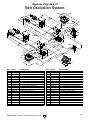
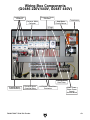
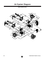
Belt Oscillation System
Replaces Page 66 & 67
IN
101
102
103
104
105
106
107
108
109
110
111
111
111
111
118
118
112
112
113
113
114
114
115
115
116
116
116
116
117
117
118
118
119
126
119
120
120
122
139
139
122
123
123
124
124
125
125
127
128
129
131
132
133
134B
135
137
138
136
138
131
132
134A
137
135
135
136
133
126
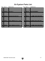
REF PART # DESCRIPTION REF PART # DESCRIPTION
101 PH29339101 FILTER CUP 123 PH29339123 CONNECTOR 1/4N X 1/8T
102 PH29339102 PRESSURE REGULATOR W/GAUGE 124 PH29339124 CONNECTOR 1/4N X 1/8T 90º
103 PH29339103 BRONZE CONNECTOR 5/16N X 1/4T 125 P04869125 BUFFER 1/8"(BRONZE)
104 PH29339104 8 X 900MM FLEXIBLE HOSE 126 P04869126 DIAPHRAGM ASSEMBLY
105 PH29339105 AIR VALVE 1/4" 127 PH29339127 CONNECTOR 5/16N X 1/8T 90º
106 PH29339106 ELBOW 1/4T X 1/4T 90º 128 PH29339128 8 X 900MM FLEXIBLE HOSE
107 PS22 PHLP HD SCR 10-24 X 5/8 129 PH29339129 8 X 1650MM FLEXIBLE HOSE
108 PH29339108 ELBOW 5/16N X 1/8T 90º 130 P04869130 6MM FLEXIBLE HOSE
109 PH29339109 SOLENOID VALVE 131 P04869131 6 X 1700MM FLEXIBLE HOSE (G0486)
110 PH29339110 T-FITTING 5/16N X 5/16N X 1/8T 131 P04879131 6 X 1800MM FLEXIBLE HOSE (G0487)
111 PH29339111 CONNECTOR 1/4N X 1/4T 132 P04869132 6 X 800MM FLEXIBLE HOSE (G0486)
112 PH29339112 MANIFOLD 1/4N 132 P04879132 6 X 950MM FLEXIBLE HOSE (G0487)
113 P04869113 CONNECTOR 5/16N X 1/4T 133 PH29339133 6 X 600MM FLEXIBLE HOSE
114 P04869114 BRONZE ELBOW 1/4T X 1/8T-90 134A PH29339134 6 X 650MM FLEXIBLE HOSE FRONT
115 PH29339115 CONNECTOR 1/4N X 1/8T 90º 134B PH29339134 6 X 300MM FLEXIBLE HOSE REAR
116 PH29339116 CONNECTOR 1/4N X 1/8T 90º 135 PH29339135 6 X 700MM FLEXIBLE HOSE
117 PH29339117 THROTTLE VALVE 1/8" 136 PH29339136 6 X 350MM FLEXIBLE HOSE
118 P04869118 CONNECTOR 1/4N X 1/8T 137 PH29339137 6 X 700MM FLEXIBLE HOSE
119 P04869119 BRONZE CONNECTOR 1/4N 138 P04869138 6 X 1500MM FLEXIBLE HOSE (G0486)
120 P04869120 CONNECTOR 1/4N X 3/8T 138 P04879138 6 X 1700MM FLEXIBLE HOSE (G0487)
122 PH29339122 AIR SWITCH 1/8" 139 P04866322 CONNECTOR 1/4N X 1/4T 90º


COPYRIGHT © APRIL 2006 BY GRIZZLY INDUSTRIAL, INC.
WARNING: NO PORTION OF THIS MANUAL MAY BE REPRODUCED IN ANY SHAPE
OR FORM WITHOUT THE WRITTEN APPROVAL OF GRIZZLY INDUSTRIAL, INC.
#BL7827 PRINTED IN TAIWAN
MODEL G0486/G0487
DOUBLE-HEAD WIDE-BELT SANDER
OWNER'S MANUAL


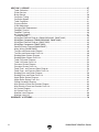
Table of Contents
INTRODUCTION ............................................................................................................................... 3
Foreword .................................................................................................................................... 3
Contact Info ................................................................................................................................
3
Control Panel Features ..............................................................................................................
4
External Features .......................................................................................................................
4
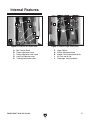
Internal Features ........................................................................................................................ 5
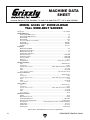
Machine Data Sheet (G0486) ....................................................................................................
6
Machine Data Sheet (
G0487) .................................................................................................... 7
SECTION 1: SAFETY .......................................................................................................................
8
Safety Instructions for
Machinery ............................................................................................... 8
Additional Safety for Wide Belt Sanders ..................................................................................
10
SECTION 2: CIRCUIT REQUIREMENTS ......................................................................................
11
220V/440V Connection ............................................................................................................ 11
Grounding ................................................................................................................................. 11
Amperage Loads ......................................................................................................................
11
Extension Cords .......................................................................................................................
11
440V Connectio
n ...................................................................................................................... 12
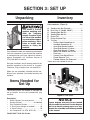
SECTION 3: SET UP ......................................................................................................................
13
Unpacking ................................................................................................................................ 13
Items Needed for Set Up ......................................................................................................... 13
Inventory ................................................................................................................................... 13
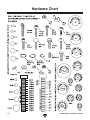
Hardware Chart ........................................................................................................................
14
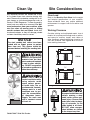
Clean Up ..................................................................................................................................
15
Site Considerations ..................................................................................................................
15
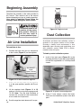
Beginning Assembly .................................................................................................................
16
Air Line Installation ...................................................................................................................
16
Dust Collection .........................................................................................................................
16
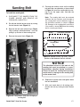
Sanding Belt .............................................................................................................................
17
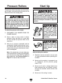
Pressure Rollers .......................................................................................................................
18
Start Up ....................................................................................................................................
18
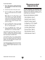
Recommended Adjustments ....................................................................................................
19
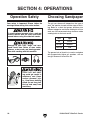
SECTION 4: OPERATIONS ...........................................................................................................
20
Operation Safety ......................................................................................................................
20
Choosing Sandpaper ...............................................................................................................
20
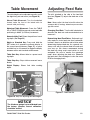
Table Movement ......................................................................................................................
21
Adjusting Feed Rate .................................................................................................................
21
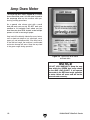
Amp Draw Meter ......................................................................................................................
22
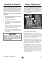
Sanding Workpiece ..................................................................................................................
23
Platen Adjustment ....................................................................................................................
23
SECTION 5: ACCESSORIES .........................................................................................................
24
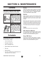
SECTION 6: MAINTENANCE ........................................................................................................
25
General ..................................................................................................................................... 25
Schedule .................................................................................................................................. 25
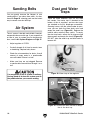
Sanding Belt
s ........................................................................................................................... 26
Air System ................................................................................................................................
26
Dust and Water Traps ..............................................................................................................
26

-2- G0486/G0487 Wide Belt Sander
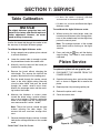
SECTION 7: SERVICE .................................................................................................................. 27
Table Calibration ......................................................................................................................
27
Platen Service ..........................................................................................................................
27
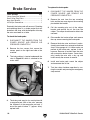
Brake Service ...........................................................................................................................
28
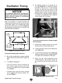
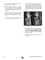
Oscillation Timing .....................................................................................................................
29
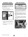
Oscillation Speed .....................................................................................................................
31
Table Parallelism ......................................................................................................................
31
Pressure Rollers .......................................................................................................................
32
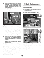
V-Belt Adjustment ....................................................................................................................
33
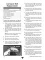
Conveyor Belt Replacement ....................................................................................................
34
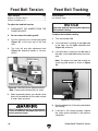
Feed Belt Tension ....................................................................................................................
36
Feed Belt Tracking ...................................................................................................................
36
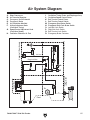
Air System Diagram .................................................................................................................
37
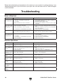
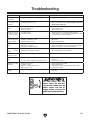
Troubleshooting ........................................................................................................................ 38
Wiring Box Electrical Diagram (G0486 220V/440V, G0487 440V) ......................................... 42
Wiring Box Components (G0486 220V/440V, G0487 440V) ................................................... 43
Wiring Box Electrical Diagram (G0487 220V) ......................................................................... 44
Wiring Box Components (G0487 220V) ................................................................................... 45
General Electric Diagram(G0486/G0487) ................................................................................ 46
Motor Wiring (G0486/G0487) ................................................................................................... 47
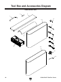
Tool Box and Accessories
Diagram ......................................................................................... 48
Tool Box and Accessories Parts List .......................................................................................
49
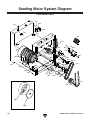
Sanding Motor System Diagram ..............................................................................................
50
Sanding Motor System Parts List .............................................................................................
51
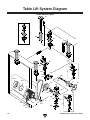
Table Lift
System Diagram ....................................................................................................... 52
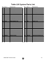
Table Lift
System Parts List ..................................................................................................... 53
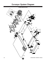
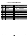
Conveyor System
Diagram ...................................................................................................... 54
Conveyor System
Parts List ..................................................................................................... 55
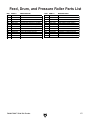
Feed, Drum, and Press
ure Roller Diagram .............................................................................. 56
Feed, Drum, and Press
ure Roller Parts List ............................................................................ 57
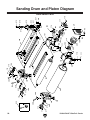
Sanding Drum and Platen Diagram ......................................................................................... 58
Sanding Drum and Platen Parts List ........................................................................................ 59
Upper Roller
System Diagram ................................................................................................. 60
Upper Roller
System Parts List ................................................................................................ 61
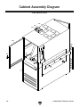
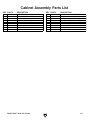
Cabinet Assembly
Diagram ...................................................................................................... 62
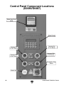
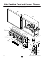
Main Electrical Panel and Controls Diagram ........................................................................... 64
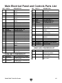
Main Electrical Panel and Controls Parts List .......................................................................... 65
Air System Diagram ................................................................................................................. 66
Air System Parts List ................................................................................................................ 67
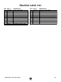
Machine Label Diagram ...........................................................................................................
68
Machine Label List ...................................................................................................................
69
WARRANTY & R
ETURNS ............................................................................................................. 70

G0486/G0487 Wide Belt Sander -3-
If you have any comments regarding this manual,
please write to us at the address below:
Grizzly Industrial, Inc.
C
/O Technical Documentation Manager
P.O. Box 2069
Bellingham, WA 98227-2069
We stand behind our machines. If you have any
service questions or parts requests, please call or
write us at the location listed below.
Grizzly Industrial, Inc.
1203 Lycoming Mall Circle
Muncy, PA 17756
Phone: (570) 546-9663
Fax: (800) 438-5901
E-Mail: [email protected]
Web Site: http://www.grizzly.com
Foreword
INTRODUCTION
Contact Info
We are proud to offer the G0486/G0487 Wide
Belt Sander
. This machine is part of a growing
Grizzly family of fine woodworking machinery.
When used according to the guidelines set forth in
this manual, you can expect years of trouble-free,
enjoyable operation and proof of Grizzly’s com
-
mitment to customer satisfaction.
We are pleased to provide this manual with the
G0486/G0487 Wide Belt Sander. It was written
to guide you through assembly, review safety
considerations, and cover general operating pro
-
cedures.
The specifications, drawings, and photographs
illustrated in this manual represent the
G0486/
G0487 Wide Belt Sander as supplied when the
manual was prepared. For your convenience, we
always keep current Grizzly manuals available on
our website at
www.grizzly.com. Any updates to
your machine will be reflected in these manuals
as soon as they are complete.

-4- G0486/G0487 Wide Belt Sander
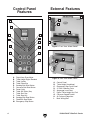
Control Panel
Features
External Features
A. Digital Amp Draw Meter
B. Table-Height Digital Readout
C. Table Up Key
D. Table Down Key
E. Sanding Belt Start Button
F. Conveyor Belt Start Button
G. Power Light
H. Table Set (Enter) Key
I. Table Start Key
J. Table Stop Key
K. Sanding Belt Stop Button
L. Feed Belt Stop Button
M. Emergency Stop Button
Figure 2. Front View, Model G0487.
Figure 1. Control Panel, Model G0487.
A. Control Panel
B. Table Height Handwheel
C. Emergency Stop Push-Panel
D. 4" Dust Collection Ports
E. Amperage Load Chart
F. Digital Table Height Key Pad
G. Conveyor Speed Control
H. Air Pressure Regulator
I. Main Wiring Box
Figure 3. Rear View Model G0487.
A
B
C
D
E
F
G
H
I
J
K
L
M
B
C
A
F
E
D
G
H
I
Page is loading ...
Page is loading ...
Page is loading ...
Page is loading ...
Page is loading ...
Page is loading ...
Page is loading ...
Page is loading ...
Page is loading ...
Page is loading ...
Page is loading ...
Page is loading ...
Page is loading ...
Page is loading ...
Page is loading ...
Page is loading ...
Page is loading ...
Page is loading ...
Page is loading ...
Page is loading ...
Page is loading ...
Page is loading ...
Page is loading ...
Page is loading ...
Page is loading ...
Page is loading ...
Page is loading ...
Page is loading ...
Page is loading ...
Page is loading ...
Page is loading ...
Page is loading ...
Page is loading ...
Page is loading ...
Page is loading ...
Page is loading ...
Page is loading ...
Page is loading ...
Page is loading ...
Page is loading ...
Page is loading ...
Page is loading ...
Page is loading ...
Page is loading ...
Page is loading ...
Page is loading ...
Page is loading ...
Page is loading ...
Page is loading ...
Page is loading ...
Page is loading ...
Page is loading ...
Page is loading ...
Page is loading ...
Page is loading ...
Page is loading ...
Page is loading ...
Page is loading ...
Page is loading ...
Page is loading ...
Page is loading ...
Page is loading ...
Page is loading ...
Page is loading ...
Page is loading ...
Page is loading ...
Page is loading ...
Page is loading ...
Page is loading ...
Page is loading ...
-
 1
1
-
 2
2
-
 3
3
-
 4
4
-
 5
5
-
 6
6
-
 7
7
-
 8
8
-
 9
9
-
 10
10
-
 11
11
-
 12
12
-
 13
13
-
 14
14
-
 15
15
-
 16
16
-
 17
17
-
 18
18
-
 19
19
-
 20
20
-
 21
21
-
 22
22
-
 23
23
-
 24
24
-
 25
25
-
 26
26
-
 27
27
-
 28
28
-
 29
29
-
 30
30
-
 31
31
-
 32
32
-
 33
33
-
 34
34
-
 35
35
-
 36
36
-
 37
37
-
 38
38
-
 39
39
-
 40
40
-
 41
41
-
 42
42
-
 43
43
-
 44
44
-
 45
45
-
 46
46
-
 47
47
-
 48
48
-
 49
49
-
 50
50
-
 51
51
-
 52
52
-
 53
53
-
 54
54
-
 55
55
-
 56
56
-
 57
57
-
 58
58
-
 59
59
-
 60
60
-
 61
61
-
 62
62
-
 63
63
-
 64
64
-
 65
65
-
 66
66
-
 67
67
-
 68
68
-
 69
69
-
 70
70
-
 71
71
-
 72
72
-
 73
73
-
 74
74
-
 75
75
-
 76
76
-
 77
77
-
 78
78
-
 79
79
-
 80
80
-
 81
81
-
 82
82
-
 83
83
-
 84
84
-
 85
85
-
 86
86
-
 87
87
-
 88
88
-
 89
89
-
 90
90


Ask a question and I''ll find the answer in the document
Finding information in a document is now easier with AI
Related papers
-
Grizzly G0486/G0487 User manual
-
-
Grizzly G0920 Owner's manual
-
 pro.point Air Belt Sander User manual
-
-
-
-
-
-

Other documents
-
General International 15-150 M1 User guide
-
Craftsman 315277251 Owner's manual
-
Wen HB3216 User manual
-
 South bend SB1096 Owner's manual
-
King Canada KC-108-OSC User manual
-
-
 Grizzly PRO T32337 Owner's manual
-
Fairchild Lower Pressure Selector Relay User manual
-
Wen HB3185 User manual
-
 Grizzly PRO T32336 Owner's manual


