Page is loading ...

12Z
12 CHANNEL RADIO CONTROL SYSTEM
PCMG3/PCM1024/FM selectable
INSTRUCTION MANUAL
1M23N16902

2
TABLE OF CONTENTS
INTRODUCTION............................................... 4
●Support and Service ......................................... 4
●Application, Export, and Modification ........... 5
●Definitions of Symbols ...................................... 6
●Safety Precautions (do not operate without
reading) ............................................................. 6
BEFORE USE ..................................................... 9
●Features of 12Z ................................................. 9
●Contents and technical specifications ........... 10
●Accessories ....................................................... 11
●Transmitter controls ....................................... 12
Cautions on handling antenna ...................... 12
LED monitor ................................................... 13
Switch (SA-SH) ............................................... 13
Volume (LD, CD, RD) .................................... 14
Slide Lever (LS, RS) ....................................... 14
Digital trim (T1-T4) ....................................... 14
Edit key ........................................................... 15
Stick Adjustment ............................................ 15
CF card ............................................................ 17
Connector/Plug ............................................... 18
Attachment and detachment of the battery . 18
RF module MZ-FM ........................................ 19
●Receiver nomenclature ................................... 20
●Safety precautions when installing receiver and
servos ............................................................... 21
BASIC OPERATION ....................................... 22
●Battery Charging ............................................ 22
How to charge the Lithium Ion Battery ....... 22
How to charge the Ni-Cd Battery ................. 22
●How to turn On/OFF the transmitter ........... 23
When turning on ............................................ 23
When turning off ............................................ 23
●How to change the frequency/How to set the
receiver's ID .................................................... 23
●In case of using PCM1024, PPM receivers ... 24
●Registration of the user's name ..................... 24
●Home screen .................................................... 25
FUNCTIONS OF SYSTEM MENU ................ 27
Trainer ............................................................. 28
Display ............................................................. 30
Sound ............................................................... 31
System Timer .................................................. 32
User Name ....................................................... 33
H/W Reverse ................................................... 35
Information .................................................... 36
MODEL BASIC SETTING PROCEDURE ... 37
●Airplane/glider basic setting procedure ........ 37
●Helicopter basic setting procedure ................ 39
●Receiver and servos connection ..................... 43
●Servo connection by model type .................... 44
FUNCTIONS OF LINKAGE MENU ............. 48
(Common Functions)
Linkage Menu functions table ...................... 48
Servo Monitor ................................................. 49
Model Select .................................................... 50
Model Type...................................................... 52
Frequency ........................................................ 54
Function .......................................................... 55
Sub-Trim ......................................................... 57
Servo Reverse ................................................. 58
Fail Safe ........................................................... 59
End Point (ATV) ............................................. 60
Throttle Cut (Airplane/helicopter only) ....... 61
Idle Down (Airplane/helicopter only) ........... 62
Swash (Helicopter only) ................................. 63
Timer ............................................................... 65
Dial Monitor ................................................... 66
Data Reset ....................................................... 67
Condition Hold switching (Helicopter only) 68
TABLE OF CONTENTS

3
TABLE OF CONTENTS
FUNCTIONS OF MODEL MENU
●Common Functions ........................................ 69
Servo Monitor (Linkage Menu 49)
Condition Select .............................................. 70
AFR (D/R) ....................................................... 72
Program Mix ................................................... 74
Fuel Mixture ................................................... 77
●Airplane/Glider/EP Glider Functions ........... 78
Model Menu functions list ............................. 78
AIL Differential .............................................. 80
Flap Setting ..................................................... 81
AIL to Camber FLP ....................................... 82
AIL to Brake FLP ........................................... 83
AIL to RUD ..................................................... 84
Airbrake to ELE ............................................. 85
RUD to AIL ..................................................... 87
Camber Mix .................................................... 88
ELE to Camber .............................................. 90
Camber FLP to ELE ...................................... 91
Butterfly .......................................................... 92
Trim Mix 1/2 ................................................... 94
Airbrake .......................................................... 96
Gyro (for GYA type gyro) .............................. 98
V-tail ................................................................ 99
Ailevator ........................................................ 100
Winglet .......................................................... 101
Motor ............................................................. 102
RUD to ELE .................................................. 103
Snap Roll ....................................................... 104
Multi Engine ................................................. 105
●Helicopter Functions .................................... 106
Model Menu functions list ........................... 106
PIT Curve/Pit trim ....................................... 107
THR Curve/Throttle hover trim ................. 110
Acceleration .................................................. 112
Throttle Hold ................................................ 113
Swash Mix ..................................................... 114
Throttle Mix .................................................. 115
PIT to Needle ................................................ 116
PIT to RUD (Revolution mix) ..................... 117
Fuel Mixture (Common functions 77)
Gyro (for GY type gyro) .............................. 118
Governor ....................................................... 119
●Common Operations used in function setup
screen ............................................................. 120
●T12Z software updating procedure ............ 127

INTRODUCTION
Thank you for purchasing the Futaba® 12Z series digital proportional R/C system. In order for you to make the best use
of your system and to fly safely, please read this manual carefully. If you have any difficulties while using your system,
please consult the manual, our online Frequently Asked Questions (on the web pages referenced below), your hobby deal-
er, or the Futaba Service Center.
Due to unforeseen changes in production procedures, the information contained in this manual is subject to change without
notice.
Support and Service: It is recommended to have your Futaba equipment serviced annually during your hobby’s “off season”
to ensure safe operation.
IN NORTH AMERICA
Please feel free to contact the Futaba Service Center for assistance in operation, use and programming. Please be sure to
regularly visit the 12Z Frequently Asked Questions web site at http://www.futaba-rc.com/faq/faq/index.html. This page
includes extensive programming, use, set up and safety information on the 12Z radio system and is updated regularly. Any
technical updates and US manual corrections will be available on this web page. If you do not find the answers to your ques-
tions there, please see the end of our F.A.Q. area for information on contacting us via email for the most rapid and conven-
ient response.
Don’t have Internet access? Internet access is available at no charge at most public libraries, schools, and other public
resources. We find internet support to be a fabulous reference for many modelers as items can be printed and saved for
future reference, and can be accessed at any hour of the day, night, weekend or holiday. If you do not wish to access the
internet for information, however, don’t worry. Our support teams are available Monday through Friday 8-5 Central time to
assist you.
OUTSIDE NORTH AMERICA
Please contact your Futaba importer in your region of the world to assist you with any questions, problems or service needs.
Please recognize that all information in this manual, and all support availability, is based upon the systems sold in North
America only. Products purchased elsewhere may vary. Always contact your region’s support center for assistance.
FOR SERVICE ONLY
Futaba Service Center
3002 N. Apollo Drive, Suite 1
Champaign, IL 61822
Phone: 217-398-0007
service@futaba-rc.com
FOR SUPPORT
(PROGRAMMING AND USER QUESTIONS)
Please start here for answers to most questions:
www.futaba-rc.com
FACSIMILE: 217-398-7721
PHONE: 217-398-8970 option 2

Application, Export, and Modification
1. This product is suitable for model airplane, surface or 50 MHz (license required) use, if on the correct frequency. It is
not intended for use in any application other than the control of models for hobby and recreational purposes. The prod-
uct is subject to regulations of the FCC and is restricted under United States law to such purposes.
2. Exportation precautions:
(a) When this product is exported from the country of manufacture, its use is to be approved by the laws governing the
country of destination which govern devices that emit radio frequencies. If this product is then re-exported to other coun-
tries, it may be subject to restrictions on such export. Prior approval of the appropriate government authorities may be
required. If you have purchased this product from an exporter outside your own country and not the authorized Futaba dis-
tributor in your country, please contact the seller immediately to determine if such export regulations have been met.
(b) Use of this product with other than models may be restricted by Export and Trade Control Regulations, and an appli-
cation for export approval must be submitted. In the US, use of 72MHz (aircraft only), 75MHz (ground models only) and
27MHz (both) frequency bands are strictly regulated by the FCC. This equipment must not be utilized to operate equip-
ment other than radio controlled models. Similarly, other frequencies (except 50MHz, for HAM operators) must not be
used to operate models.
3. Modification, adjustment, and replacement of parts: Futaba is not responsible for unauthorized modification, adjust-
ment, and replacement of parts on this product. Any such changes may void the warranty.
The Following Statement Applies to the Receiver (for U.S.A.)
This device complies with part 15 of the FCC rules. Operation is subject to the following two conditions:
(1) This device may not cause harmful interference.
(2) This device must accept any interference received, including interference that may cause undesirable operation.
The RBRC
™
SEAL on the nickel-cadmium battery contained in Futaba products indicates that Futaba
Corporation of America is voluntarily participating in an industry-wide program to collect and recycle these
batteries at the end of their useful lives, when taken out of service within the United States. The RBRC pro-
gram provides a convenient alternative to placing used nickel-cadmium batteries into the trash or municipal
waste system, which is illegal in most areas.
You may contact your local recycling center for information on where to return the spent battery. Please call 1-800-8-BAT-
TERY for information on battery recycling in your area. Futaba Corporation of America’s involvement in this program is
part of it’s’ commitment to protecting our environment and conserving natural resources.
NOTE: Our instruction manuals encourage our customers to return spent batteries to a local recycling center in order to
keep a healthy environment. RBRC is a trademark of the Rechargeable Battery Recycling Corporation.

Definitions of Symbols
Pay special attention to safety where indicated by the following symbols.
DANGER – Procedures which may lead to dangerous conditions and cause death/serious injury if not carried out
properly.
WARNING – Procedures which may lead to a dangerous condition or cause death or serious injury to the user if
not carried out properly, or procedures where the probability of superficial injury or physical damage is high.
CAUTION – Procedures where the possibility of serious injury to the user is small, but there is a danger of injury,
or physical damage, if not carried out properly.
= Prohibited = Mandatory
Warning: Always keep electrical components away from small children.
FLYING SAFETY
To ensure the safety of yourself and others, please observe the following precautions:
Have regular maintenance performed. Although your 12Z protects the model memories with non-volatile
EEPROM memory (which does not require periodic replacement) and not a battery, it still should have regular
checkups. We recommend sending your system to the Futaba Service Center annually during your non-flying
season for a complete checkup and service.
Use the Fail-Safe safety feature to set the throttle to low-idle in case of signal loss or RX battery failure.
Engine power will be automatically reduced to help limit personal or property damage. Refer to the Failsafe
Setting Procedure listed in the index.
Receiver Ni-Cd Battery
Charge the batteries! (See Charging the batteries listed in the index for details.) Always recharge the receiver
batteries for at least 8 hours before each flying session. A low battery will soon die, causing loss of control and a
crash. When you begin your flying session, reset your timer, and during the session pay attention to the duration
of usage.
CAUTION: The initial charge on new NiCd receiver batteries should be done for 15 hours using the slow-charger
that came with the radio system. This will “condition” the batteries so that the next charge may be done using the
fast-charger of your choice. If the initial charge is done with a fast-charger the batteries may not reach their full cap-
acity and you may be flying with batteries that are only partially charged.
Where to Fly
We recommend that you fly at a recognized model airplane flying field. You can find model clubs and fields by asking your
nearest hobby dealer, or in the US by contacting the Academy of Model Aeronautics. You can also contact the national
Academy of Model Aeronautics (AMA), which has more than 2,500 chartered clubs across the country. Through any one
of them, instructor training programs and insured newcomer training are available. Contact the AMA at the address or
toll-free phone number below.
Academy of Model Aeronautics
5151 East Memorial Drive
Muncie, IN 47302-9252
Tel. (800) 435-9262
Fax (765) 741-0057
or via the Internet at http:\\www.modelaircraft.org

Lithium-ION Battery Safety and Handling instructions
It is important to understand the operating characteristics of lithium-ion (Li-Ion) batteries. Always read the specifications
printed on the label of your Li-Ion battery and charger prior to use. Failure to follow the proceeding precautions can
quickly result in severe, permanent damage to the batteries and its surroundings and possibly result in a FIRE!
IMPORTANT PRECAUTIONS
Do not attempt to disassemble Li-Ion packs or cells.
Do not allow Li-Ion cells to come in contact with moisture or water at any time.
Always provide adequate ventilation around Li-Ion batteries during charge, discharge, while in use, and during
storage.
Do not leave a Li-Ion battery unattended at any time while being charged or discharged.
Do not attempt to charge Li-Ion batteries with a charger that is NOT designed for Li-Ion batteries, as permanent
damage to the battery and charger could result.
Always charge Li-Ion batteries in a fireproof location. Do not charge or discharge Li-Ion batteries on carpet, a
cluttered workbench, near paper, plastic, vinyl, leather or wood, or inside an R/C model or full sized automobile!
Monitor the charge area with a smoke or fire alarm, and have a lithium-approved “ABC type” fire extinguisher
available at all times.
Do not charge Li-Ion batteries at currents greater than the “1C” rating of the battery (“C” equals the rated capacity of the
battery).
Do not allow Li-Ion cells to overheat at any time! Cells which reach greater than 140 degrees Fahrenheit (60
o
C)
should be placed in a fireproof location.
Li-Ion cells will not charge fully when too cold or show full charge.
It is normal for the batteries to become warm during charging, but if the charger or battery becomes excessively hot
disconnect the battery from the chargerimmediately!! Always inspect a battery which has previously overheated for
potential damage, and do not re-use if you suspect it has been damaged in any way.
Do not use a Li-Ion battery if you suspect physical damage has occurred to the pack. Carefully inspect the battery
for even the smallest of dents, cracks, splits, punctures or damage to the wiring and connectors. DO NOT allow the
battery’s internal electrolyte to get into eyes or on skin—wash affected areas immediately if they come in contact with
the electrolyte. If in doubt, place the battery in a fire-proof location for at least 30 minutes.
Do not store batteries near an open flame or heater.
Do not discharge Li-Ion batteries at currents which exceed the discharge current rating of the battery.
Always store Li-Ion cells/packs in a secure location away from children.
Compact Flash (CF) Card Handling Instructions
Follow these precautions when handling the CF card 1RVKQPCN.
IMPORTANT! The Lithium-Ion (Li-Ion) batteries included in the 1Z transmitter are not to be confused with
Lithium-Polymer (LiPo) batteries, or any other type of rechargeable battery (including NiCd’s and NiMH’s). Li-Ion
batteries require special charging criteria different than other rechargeable batteries. Use only the Futaba lithium ion
transmitter charger included with this set for, or other chargers approved by Futaba to charge the Li-Ion batteries in
the 1Z transmitter.
Never remove the CF card or turn off power while
entering data.
Never store the CF card where it may be subject to
strong static electricity or magnetic fields.
Do not expose the CF card to direct sunlight, excessive
humidity or corrosive environments.
Do not expose the CF card to dirt, moisture, water or
fluids of any kind.
Always hold the CF card by the edges during installa-
tion and removal.
Be certain to insert the CF card in the correct direction.
Always use Futaba CF card.

AT THE FLYING FIELD
Always pay particular attention to the flying fields’ rules, as well as the presence and location of spectators, the wind
direction, and any obstacles on the field. Be very careful flying in areas near power lines, tall buildings, or communication
facilities as there may be radio interference in their vicinity. If you must fly away from a club field, be sure there are no other
modelers flying within a three-to-five-mile range, or you may lose control of your aircraft or cause someone else to lose con-
trol.
Before flying, be sure that the frequency you intend to fly with is not in use, and secure any frequency control
device (pin, tag, etc.) for that frequency before turning on your transmitter. It is never possible to fly two or more mod-
els on the same frequency at the same time. Even though there are different types of modulation (AM, FM, PCM), only
one model may be flown on a single frequency at any one time.
Stop flying long before your batteries become low on charge. Do not rely on your radio’s low-battery warning sys-
tems, which are intended only as a precaution, to tell you when to recharge. Always check your transmitter and
receiver batteries prior to each flight.
To prevent possible damage to your radio gear, turn the power switches on and off in the proper sequence:
1. Set the throttle stick to the idle position, or otherwise disarm your motor/engine.
2. Fully extend the transmitter antenna.
3. Turn on the transmitter power and allow your transmitter to reach its home screen.
4. Confirm the proper model memory has been selected.
5. Turn on your receiver power.
6. Test all controls. If a servo operates abnormally, don’t attempt to fly until you determine the cause of the problem. (For
PCM systems only: Test to ensure that the Failsafe settings are correct by waiting at least 2 minutes after adjusting then,
turning the transmitter off and confirming the proper surface/throttle movements. Turn the transmitter back on.)
7. Start your engine.
9. After flying, bring your throttle stick to idle position, engage any kill switches or otherwise disarm your
motor/engine.
10. Turn off receiver power.
11. Turn off transmitter power.
If you do not turn on your system in this order, you may damage your servos or control surfaces, flood your engine, or in
the case of electric-powered or gasoline-powered models, the engine may unexpectedly turn on and cause a severe injury.
While you are getting ready to fly, if you place your transmitter on the ground, be sure that the wind won’t tip
it over. If it is knocked over, the throttle stick may be accidentally moved, causing the engine to speed up. Also, dam-
age to your transmitter may occur.
Before taxiing, be sure to extend the transmitter antenna to its’ full length. A collapsed antenna will reduce your
flying range and cause a loss of control. It is a good idea to avoid pointing the transmitter antenna directly at the model,
since the signal is weakest in that direction.
Don’t fly in the rain! Water or moisture may enter the transmitter through the antenna or stick openings and cause
erratic operation or loss of control. If you must fly in wet weather during a contest, be sure to cover your transmitter
with a waterproof barrier. Never fly if lightning is expected.
Never turn the transmitter off during flight! Switching the transmitter off and on during flight will very likely cause
a crash because of the time required for the transmitter to "reboot" and become fully functional.
8. Complete a full range check.

9
<Before Use>
BEFORE USE
FEATURES
PCMG3 (PCM Generation 3)
PCMG3 has a 40% faster response than current PCM1024. The resolution is 2048, which is double
the current PCM1024. It can operate up to 12 Channels. The multi-level modulation technology has been
implemented for the R/C industry to achieve the highest performance available today.
WFSS (Wireless Frequency Setting System)
The construction of both transmitter (T12Z) and receiver (R5014) are a frequency synthesizer system.
Model types
Seven types of main wings and three types of tail wings are available for airplanes. Seven swash types
are available for helicopters. Seven types of main wings and three types of tail wings are available for
gliders. Functions and mixing functions necessary for each model type are set in advance at the factory.
Mixing functions
The T12Z transmitter continues the functions of the higher class model T14MZ and meets the need for
prcise setting at meets, etc. by use of abundant curve mixing functions
Data input
Large graphic LCD and new type edit keys substantially improve ease of setup. Omni directional cursor
lever, rotating data input dial which allows quick data input, and two kinds of return key are provided
Stick
Each axis is supported by dual ball bearings. This allows for finer and more precise operation, the new
potentiometers also offer longer life.
Li-ion battery
T12Z is operated by 7.4V/2,200 mAh Lithium-Ion battery.
R5014DPS
The R5014DPS is a small 14CH synthesized receiver with high sensitivity and selectability.
CF (Compact Flash) card (Optional)
Model data can be saved in an optional Futaba CF card (CFDP32M, etc.) When T12Z transmitter
software updating files are released, the software can be updated by using a CF card.

10
<Before Use>
Contents and Technical Specifications
(Specifications and ratings are subject to change without notice.)
Your 12ZA/12ZH/12Z (packaged with a 14-channel PCM-G3 receiver) includes the following components:
• T12Z Transmitter, including RF module (MZ-DDS)
• R5014 Receiver
• LT2F2200 Li-ion battery & LBC-1D5 Charger
• NR4F1500 Ni-Cd battery & Charger (except for
Australia)
• Switch harness/DSC cord
• Hex Wrench (1.5mm, 2.5mm)
• Neck strap
The set contents depend on the type of set.
Transmitter T12ZA/T12ZH/T12Z
Operating system: 2-stick, 12 channels, PCM-G3,
synthesizer system
Transmitting frequency: 29, 35, 36, 40, 41, or 72 MHz
bands
Modulation: PCM-G3, PCM1024, or FM/PPM
switchable.
Power supply: 7.4V LT2F2200 Li-ion battery
Current drain: 500mA average
Receiver R5014DPS
(PCM-G3, Synthesizer, Dual conversion)
Receiving frequency: 29, 35, 36, 40, 41, or 72 MHz
bands
Intermediate freq.: 10.7 MHz & 450 kHz
Power requirement: 4.8 V Ni-Cd battery
Current drain: 75 mA
Size: 52x37.5x16.5 mm
Weight: 33 g.
Channels: 14
Suggested Servos for use with your 12Z
Servo S9154 (Digital servo)
Control system: Pulse width control, 1.52 ms neutral
Power requirement: 4.8 V (from receiver)
Output torque: 63.9 oz.-in. (4.6 kg-cm) at 4.8V
Operating speed: 0.14 sec/60 at 4.8V
Size: 1.87 x 1.06 x 0.97 in. (47.5 x 27.0 x 25.3 mm)
Weight: 1.87 oz. (53 g)
Servo S9255 (Digital servo)
Control system: Pulse width control, 1.52 ms neutral
Power requirement: 4.8 V (from receiver)
Output torque: 125.0 oz.-in. (9.0 kg-cm) at 4.8V
Operating speed: 0.16 sec/60 at 4.8V
Size: 1.57 x 0.79 x 1.44 in. (40.0 x 20.0 x 36.6 mm)
Weight: 1.94 oz. (55 g)

11
<Before Use>
• Compact Flash Memory card - CFDP 32M Data-Pack increases your model file storage capability, and
allows you to transfer model settings to another T12Z transmitter.
• LT2F2200 Transmitter battery pack - the (2200mAh) transmitter Li-ion battery pack may be easily
exchanged with a fresh one to provide enough capacity for extended flying sessions.
• Trainer cord - the optional training cord may be used to help a beginning pilot learn to fly easily by
placing the instructor on a separate transmitter. Note that the T12Z transmitter may be connected to
another T12Z system, as well as to any other models of Futaba transmitters. The T12Z transmitter uses
the newer “Micro” rectangular type cord plug. Both Micro- to-Micro and Micro-to-round plug style
trainer cords are available.
• Neckstrap - a neckstrap may be connected to your T12Z system to make it easier to handle and improve
your flying precision since your hands won’t need to support the transmitter’s weight.
• Y-harnesses, servo extensions, etc - Genuine Futaba extensions and Y-harnesses, including a heavy-duty
version with heavier wire, are available to aid in your larger model and other installations.
• Gyros - a variety of genuine Futaba gyros are available for your aircraft or helicopter needs.
• Governor (GV1) - for helicopter use. Automatically adjusts throttle servo position to maintain a constant
head speed regardless of blade pitch, load, weather, etc.
• DSC Cord - allows setup and testing without transmitting. With your Transmitter and Receiver off, plug
cord into trainer port then, into the receiver Battery/DSC (B/C) slot. All programming and setup may be
done in this manner without transmitting.
• Receivers - various models of Futaba receivers may be purchased for use in other models. (Receivers for
PCM-G3, PCM1024, or FM/PPM types are available.)
• Optional Charger - Futaba CR-2500 Li-Ion Transmitter/Receiver Battery Charger.
The following additional accessories are available from your dealer. Refer to a Futaba catalog for
more information:

12
<Before Use>
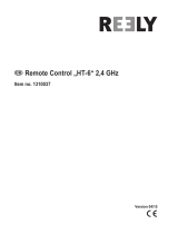
Transmitter controls
Cautions on handling antenna
WARNING
Be sure to attach the antenna before operation.
*Antenna is stored in the antenna storage box in the trans-
mitter.
Extend the antenna to the full extent, and make
sure that the antenna is securely locked before
operation.
Never hold the antenna alone.
*Hold the carrying bar, otherwise the main body can be
damaged.
(J1)
(J2)
(J4)
(J3)
●Antenna
●Volume
●Monitor LED
●Return Key
●Data Input Dial
/Enter Button
●LCD Display
●Carring Bar
●Speaker
●Switch Block
(SC,SD,SG,SH)
●Switch Block
(SA,SB,SE,SF)
●Slide
Lever
(LS)
●Digital
Trim
●Hook
●Power
Switch
(T3,T4)
●Digital
Trim
●Cursor Lever
(T3,T4)
(LD,CD,RD)
●Slide Lever
(RS)
●Stick
●Stick

13
<Before Use>
•Removing and storing the antenna
When removing the antenna from the antenna
compartment, hold the transmitter level so that
the antenna will not fly out and fall, then push the
antenna eject button.
When storing the antenna, push the antenna in
until it is locked positively
●Antenna
●Eject Button
•Mounting and dismounting the antenna
Mount the antenna by turning it clockwise until
it locks in place.
Clockwise
• When dismounting the antenna, turn the
antenna counterclockwise
•Angle adjustment of the antenna
You can change the angle of the antenna, as
you like. Use 2.5mm hexagonal wrench to turn
counterclockwise to release the screw on the left
of the antenna holder, and change the angle of the
antenna, as you like, then retighten.
●Screw
LED monitor
The color of the 12Z logo mark shows the status
of the transmitter.
●LED Monitor
(LED Display)
• When you turn on the transmitter, 12Z logo
shows different colors, and then the color
stays constantly pink. The 12Z logo blinks
green very rapidly while internal processing
i
s carried out after the power is turned on.
On
ce the internal processing is over, the logo
turns
to pink color.
• The 12Z logo turns blue when you use the DSC
cable, or when the trainer function is set at
student's side.
• The 12Z logo blinks red slowly when you
attach the RF module that is different from
the setting.
• Under the normal usage (, that is, radio wave
is being emitted), the 12Z logo turns green.
Switch (SA-SH)
(Switch Type)
• SA : 3 positions; Alternate; Short lever
• SB : 3 positions; Alternate; Long lever
• SC : 3 positions; Alternate; Long lever
• SD : 3 positions; Alternate; Short lever
• SE : 3 positions; Alternate; Short lever
• SF : 2 positions; Alternate; Long lever
• SG : 2 positions; Alternate; Short lever
• SH : 2 positions; Momentary; Long lever
*You can choose switch and set the ON/OFF-direction in the
setting screen of the mixing functions.

14
<Before Use>
Volume
Volume LD, CD, and RD:
The volume LD and RD are analog type. You can
recall the dial position data at the last operation in
the Dial Monitor screen (Linkage Menu function.)
The volume CD is digital type (rotary encoder).
This volume works as both a volume and a push-
switch.
*T12Z beeps when the volume knob reaches center.
*You can check the volume position of the LD/RD functions
in the Dial Monitor screen in the Linkage menu.
*You can use each setting screen of the mixing functions to
select volumes and defi ne the direction of its movement.
Slide Lever
LS (Left), RS (right):
The side lever LS and RS are analog type.
You can recall the lever position data at the last
operation in the Dial Monitor screen (Linkage
Menu function.)
*T12Z beeps when the lever comes to the center.
*You can check the lever position on the dial-monitor screen
in the linkage menu.
*You can select a slide lever and set the movement direction
on the setting screen of mixing functions.
Digital trim
This transmitter is equipped with digital trims.
Each time you press a trim button, the trim position
moves one step. If you continue pressing it, the trim
position starts to move faster. In addition, when
the trim position returns to the center, the tone will
change. You can always monitor trim positions by
graphics on the screen.
To change the trim rate, you must activate this
through the function menu, within the linkage
menu. Use the cursor lever to select the trim box
and then push the enter button and you will access
another screen which enables you to change the
trim percentages.
Note: The trim positions you have set will be stored in the
non-volatile memory and will remain there.

15
<Before Use>
LCD screen:
The LCD screen contrast can be adjusted by
system menu screen setting [DISPLAY].
Return key:
Push the return key (HOME) when you want
to return directly to the home screen and push the
return key (RETURN) when you want to return to
the preceding screen.
Cursor lever:
The cursor lever controls movement of the cursor
on menu screens and movement of the cursor
among setting items on setup screens. Up, down,
left, and right movements are possible.
Push the cursor lever when you want to go
directly to the next page (if there is next page.)
Data input dial/enter button
This dial/button is used during data input. Value
input, mode selection, and similar operations can be
performed by turning the dial to the left and right.
This dial/button can also be used as the enter
button when a confirmation message is displayed
on the screen, etc.
Edit Key
Data input operation is performed using the cursor lever, data input dial/enter button, and return key.
HOME
CURSOR
DATA
RETURN
DIGITAL PROPORTIONAL RADIO CONTROL SYSTEM
PUSH
●Return key (HOME)
●Cursor (CURSOR)
●Data input dial/Enter button
(DATA)
●LCD screen
●Return key (RETURN)
Stick Adjustment
Use the attached 1.5mm hexagonal wrench
to turn the screw clockwise to adjust the stick
outwards, or counter-clockwise to tilt it inward.
Note: The screw will fall out if you turn the screw counter-
clockwise too far.
Adjustment of the stick lever angle
You can make fine adjustments to the angle of a
stick lever outwards from the initial position.
●Screw

16
<Before Use>
Adjustment of the stick lever length
You can adjust the length of stick levers, as you
like. It is recommended to adjust the length of the
sticks in line with your hand size.
Lever Head
A
Lever Head
B
1. Hold the lever head "B" and turn the lever
head "A" counter-clockwise, the lock will be
released.
2. Turn the lever-head "A" clockwise as you hold
the lever-head "B" after placing it as you like.
Adjustment of stick lever tension
The tension of the self-return type stick lever can
be adjusted.
1. Remove the rubber grip on the back of the
transmitter.
●Stick
Tension
(J1)
(Mode 1/2)
●Stick Tension(J2)
(Mode 2)
●Stick Tension(J4)
(Mode 1/2)
●Stick Tension(J3)
(Mode 1)
2. Use the accessory 1.5mm hexagonal wrench
to adjust the spring strength as you prefer by
turning the adjusting screw of the stick you
want to adjust.
*Turning the screw clockwise increases the tension.
3) At the end of adjustment, re-install the
rubber grip.
Adjustment of Throttle Stick (Ratchet System)
You can also choose either airplane ratchet
system or helicopter-touch.
●Retaining Force (J2)
(Mode 1)
●Retaining
Force (J3)
(Mode 2)
1. Open the dust protection cap on the back
of the transmitter that is covering the hole for
throttle stick adjustment.
2. Use the attached 1.5mm hexagonal wrench
to turn the adjustment screw and set it as you
prefer. Turning the screw clockwise increases
the tension.
Hole for throttle
stick adjustment
For airplane (Mode1)
For helicopter (Mode2)
For helicopter (Mode1)
For airplane (Mode2)
*This transmitter has two ratchet plates, one for airplane
and the other one for helicopter. If you tighten both screws,
you won't be able to achieve the adjustment that you need
because of the overlap of those two adjustments.
*If you want to change the setting from airplane to helicopter
(or from helicopter to airplane), turn counterclockwise until
the throttle stick moves freely. Then turn the screw for the
helicopter (or airplane) until you get the tension you like.

17
<Before Use>
CF Card CFDP32M (Optional)
The T12Z transmitter model data can be stored
by using an optional CF (Compact Flash) card.
When T12Z transmitter software update software
is released, the software is updated using a CF
card. CF card memory size is 32MB.
Warning
Be sure to turn off the power to the transmitter
before inserting or removing the CF card.
As the CF card is a precision device, do not use
excessive force when inserting.
Be sure to use only Futaba's original CF card,
CFDP32M, for the T12Z transmitter.
* Futaba does not recommend any CF cards other than
Futaba's original CF cards.
Inserting/removing the CF card
1. Turn off the transmitter power and then open
the cover (rubber) at the left side of the
transmitter.
●Eject button
●Side Cover
●CF card
2.
[Inserting the card]
*Turn the CF card so that the front of the card faces the back
of the transmitter and slide the card into the card slot.
*Push in the card until it touches bottom. At the same time,
the eject button pops out.
[Removing the card]
*When the eject button is pushed; the CF card is pushed out
and can be removed.
3. Close the cover (rubber).
Read data from a PC
Saving model data and update files (released
from Futaba) into the CF card, you can use those
files on your T12Z transmitter. Equipment for
reading and writing CF cards are available at most
electronics stores.
[Important]: Before saving data from the PC,
insert the CF card into the transmitter and
turn on the power. To save a model data file
f
rom the PC, copy the file to the "MODEL"
folder, which is automatically written.
*Use only CF card reader/writer that complies with CFA
(CompactFlashTM Association) standard.
Stored data
The life of the CF card is limited due to the use
of Flash memory. When you have a problem of
saving or reading data such as picture data after a
long period of use, please get a new CF card.
*We do not have the responsibility of compensating any
failure or damage to the data stored in the memory card no
matter what the reason is. Be sure to keep the backup of
your important data in your CF card.
*No necessity for backup; T12Z transmitters and CF cards
are using nonvolatile memory devices so that the data
stored in those will not be lost, even when the main battery
is removed.

18
<Before Use>
Connector/Plug
●DSC/Trainer
Connector for trainer function (TRAINER)
When you use trainer function, connect the
optional trainer cable between the transmitters for
teacher and student.
*You can set the trainer function on the Trainer Function
screen in the system menu.
Connector for DSC function (DSC)
You can operate the transmitter without
transmitting radio waves by connecting the
transmitter and the receiver to the DSC cable.
*Please refer to the section "Connection between Receiver/
Servo"
Connector for battery charger (CHG)
●Battery charge
This is the connector for charging the Lithium
Ion battery LT2F2200 that is installed in the
transmitter. Do not use any other chargers except
CR-2500 that is for 12V application to charge the
LT2F2200 battery through this connector.
Danger
Do not connect any other chargers except
CR-2500 to this charging connector.
*If you take out the Lithium Ion battery LT2F2200 from the
transmitter, you can use the attached charger LBC-1D5 for
charging the battery.
Installing and Removing of the battery
LT2F2200 for the transmitter
Attachment of the battery
1. Hook your finger in the slit formed by the
transmitter’s main body and the battery
cover on the bottom of the transmitter, and
then pull up the cover to release the lock.
You can now open the cover.
2. Move the slide lever to the right and then
install the battery in the holder.
●Move the slide lever to the far right.
3. Push the battery to the left with your finger.
4. Close and lock the battery cover completely.

19
<Before Use>
Removing of the battery
Note: If you remove the battery while the
power is on, the data you have set will not
be saved.
1. Hook one of your fingers in the slit formed
by the transmitter’s main body and the
battery cover on the back and bottom of
the transmitter, and then pull up the cover to
release the lock. You can now open the cover.
2.
Slide the slide lever to the right while pressing
it, the battery will be released.
Warning
Be careful to not drop the battery.
Never take out the battery from the T12Z
transmitter while the LED monitor is blinking
yellow after turning off the power the
T12Z transmitter.
* Internal devices such as memories may be damaged.
* If there is any problem, the message "Backup Error" will
be shown the next time when you turn on the power of the
transmitter. Do not use the transmitter as it is, send it to the
Futaba Service Center.
RF module MZ-FM
●Module
●Connector
Caution
Be sure to turn off the power of the transmitter
before you attach or detach the module.
Detachment of the RF module
Pull the module straight while you are pushing
inward the projections on both sides of the module.
*There is a connector above and under the module
respectively. So, you might find difficulty in pulling out the
module if the module is tilted.
Attachment of the RF module
Insert the module with care so that the connecter
pins of the transmitter won't be bent.

20
<Before Use>
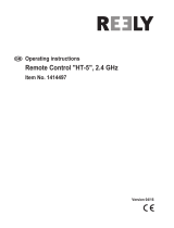
Receiver R5014DPS
●Antenna
●Connectors
●DG1
●Monitor LED
●CH1 12
●DG2
●B/C
Connector
"1 through 12": outputs for the channels 1 through 12
"DG1", "DG2": outputs of DG1 and DG2 channels
"B/C": connector for the power and DSC.
LED Monitor
This monitor is used when changing the
frequency of the receiver.
Receiver nomenclature
Before using the receiver, be sure to read the precautions listed in the following pages.
/