
52086133 REV1 © 2019 Greenlee Tools, Inc. 1/19
Read and understand all of the instructions and safety information in
this manual before operating or servicing this tool.
Lea y entienda todas las instrucciones y la información sobre
seguridad que aparecen en este manual, antes de manejar estas
herramientas o darles mantenimiento.
Lire attentivement et bien comprendre toutes les instructions et
les informations sur la sécurité de ce manuel avant d’utiliser ou de
procéder à l’entretien de cet outil.
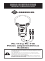
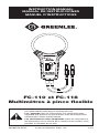
FC-110 and FC-118
Flex Clamp Meters
INSTRUCTION MANUAL
MANUAL DE INSTRUCCIONES
MANUEL D’INSTRUCTIONS
FC-110
Español.............11
Français ...........21

2
Table of Contents
Description ....................................................................................................2
Safety ............................................................................................................ 2
Important Safety Information ......................................................................3–4
Identication ..................................................................................................5
Operation ...................................................................................................6–7
Typical Measurements and Accuracy .............................................................8
Specications ................................................................................................9
Measurement Categories ............................................................................... 9
Statement of Conformity ..............................................................................10
Maintenance ................................................................................................10
Description
The Greenlee FC-110 and FC-118 Flex Clamp Meters are hand-held testing devices
that measure AC current. These meters are designed to be placed on or removed from
insulated or uninsulated conductors.
Safety
Safety is essential in the use and maintenance of Greenlee tools. This instruction
manual and any markings on the tool provide information for avoiding hazards
and unsafe practices related to the use of this tool. Observe all of the safety
information provided.

FC-110 • FC-118
3
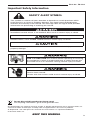
SAFETY ALERT SYMBOL
This symbol is used to call your attention to hazards or unsafe practices which
could result in an injury or property damage. The signal word, dened below,
indicates the severity of the hazard. The message after the signal word provides
information for preventing or avoiding the hazard.
Immediate hazards which, if not avoided, WILL result in severe injury or death.
Hazards which, if not avoided, COULD result in severe injury or death.
Hazards or unsafe practices which, if not avoided, MAY result in injury or
property damage.
Read and understand this material before operating or servicing
this equipment. Failure to understand how to safely operate this
tool could result in an accident causing serious injury or death.
Electric shock hazard:
Contact with live circuits could result in severe injury or death.
Important Safety Information
Do not discard this product or throw away!
For recycling information, go to www.greenlee.com.
All specications are nominal and may change as design improvements occur. Greenlee Tools, Inc.
shall not be liable for damages resulting from misapplication or misuse of its products.
® Registered: The color green for electrical test instruments is a registered trademark
of Greenlee Tools, Inc.
KEEP THIS MANUAL

4
Important Safety Information (cont.)
Electric shock and re hazard:
• Do not expose this unit to rain or moisture.
• Do not use the unit if it is wet or damaged.
• Clamp meter, leads or any other clamp accessory, when used to make a
measurement, create a System. The System is rated for CAT IV 600V
when using the leads or accessories provided with the meter. The System
CAT and voltage rating is limited by the lowest rated component in the
System when using leads or accessories not provided with the meter.
• Inspect the leads or accessory before use. They must be clean and dry, and the
insulation must be in good condition. Do not use the test lead if the contrasting
inner layer of insulation is visible.
• Use this unit for the manufacturer’s intended purpose only, as described in this
manual. Anyotheruse can impair the protection provided by the unit.
Failure to observe these warnings could result in severe injury or death.
Electric shock hazard:
• Do not apply more than the rated voltage between any two input terminals, or
between any input terminal and earth ground.
• Keep hands and ngers below the barriers on the leads and the clamp meter body.
Failure to observe these warnings could result in severe injury or death.
Electric shock hazard:
• Do not operate with the case open.
Failure to observe these warnings could result in severe injury or death.
Electric shock hazard:
• Unless measuring current, shut off and lock out power. Make sure that all capacitors
are discharged. Voltage must not be present.
• Using this unit near equipment that generates electromagnetic interference can
result in unstable or inaccurate readings.
Failure to observe these warnings could result in severe injury or death.
Electric shock hazard:
• Do not attempt to repair this unit. It contains no user-serviceable parts.
• Do not expose the unit to extremes in temperature or high humidity. Refer to
“Specications.”
Failure to observe these precautions may result in injury and can damage the unit.

FC-110 • FC-118
5
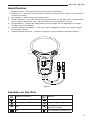
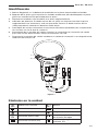
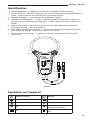
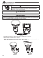
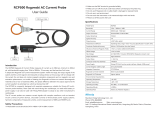
Identication
1. Rogowski Coil - The measurement coil of ex clamp meter
2. Clamp Lock – Turn the knob counter clockwise to unlock the clamp; turn clockwise
to lock the clamp
3. Coil Support - Fixes coil to the clamp meter
4. Power Indicator – The LED will be illuminated when the clamp meter is powered on
and in normal operation. The LED will ash when the batteries are low.
5. Range Switch – Select the appropriate current range for the application; Ranges
are 30A, 300A and 3000A
6. Output Voltage Description – Lists the output voltage resolution for a given range.
All voltages are AC.
7. Output Voltage Terminal – Outputs voltage to an AC voltage measuring device.
Symbols on the Unit
FC-110
1
2
3
4
5
6
7
Double Insulation Battery
Grounding AC/DC
Warning High Voltage Danger
AC
Complies with European
Union Standards
DC ETL Standard Certication
Figure 1

6
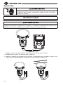
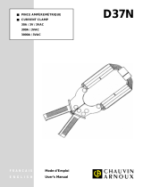
Operation
Electric shock hazard:
Contact with live circuits could result in severe injury or death.
Keep your hands away from the Rogowski coil and conductor to be measured.
Disconnect all power supplies from the device before measurement. When measuring
uninsulated conductors, do not power on the wire to be tested until the meter has
safely clamped the wire.
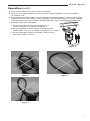
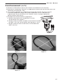
1. Turn off the clamp meter as well as the conductor being measured.
2. Unlock the clamp according to Figure 3
3. Use the measuring head to wrap around the conductor to be measured and lock it
in place. (Only one wire can be tested at a time; See Figure 4)
1
2
FC-110 FC-110
Figure 3 Figure 4
FC-110
Figure 2

FC-110 • FC-118
7
Operation (cont.)
4. Turn on the clamp, then turn on the conductor.
5. Connect the clamp meter to an AC Voltage measuring device with a resolution
of at least 1mV.
6. Read the value displayed on the AC voltage measuring device. If the current to be
measured is over the range, a value greater than 3V will display on the AC voltage
measuring device. Please select the appropriate range. (30.00A/300.0A/3000A)
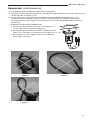
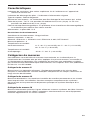
7. Improper operation examples:
a. Do not test more than one conductor at a
time as shown in as shown in Figure 5
b. Do not attempt to twist, bend, or wrap the coil
of the CMF-110/118 as shown in Figures 6, 7, and 8.
c. Do not attempt to pull on or apply a force to the
coil of the CMF-110/118
FC-110
Figure 6
Figure 8
Figure 7
Figure 5

8
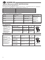
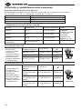
Typical Measurements and Accuracy
Electrical Accuracy Specications
The Temperature Coefcient is 20% of accuracy per °C difference from 18 °C between
0 °C and 18 °C and from 28 °C between 28 °C and 50 °C.
Accuracy ± (%reading)
Temperature 23° C±5° C
Humidity ≤ 80% RH
Temperature Coefcient 0.2 x (accuracy)/°C
(1) FC-110/118 AC Current Measurement
Range Resolution
Accuracy (At
Centered Position)
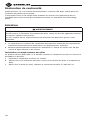
Cable Position
30.0A 0.1A ±(3%+0.5A)
Accuracy when
measuring
in centered
position.
Please refer
to gures 9
and 10.
300A 1A ±(3%+5A)
3000A 10A ±(3%+50A)
Frequency Response 45Hz-500Hz – –
FC-118 Accuracy
Additional
accuracy range
when measuring
outside of
optimum location
(when no other
electrical or
magnetic elds
are present)
Center for optimal
measurement
± (3%+5)
35mm (1.4 inches) Add 1.0% Region A
50mm (2.0 inches) Add 1.5% Region B
60mm (1.4 inches) Add 2.0% Region C
FC-110 Accuracy
Additional
accuracy range
when measuring
outside of
optimum location
(When no other
electrical or
magnetic elds
are present)
Central optimum
measurement
location
±(3%+5)
FC-110
15mm
(0.6”) away
from center
Additional 2.0% Region A
25mm
(1.0”) away
from center
Additional 2.5% Region B
35mm
(1.4”) away
from center
Additional 3.0% Region C
FC-110
Figure 9
Figure 10

FC-110 • FC-118
9
Specications
Overload Indication: Greater than 3V will be displayed on the AC voltage
measuring device
Low Battery Indication: Power Indicator ashes
Sensor Type: Rogowski Coil
Impact strength: The meter can be dropped from 1 meter's height
Clamp size: The FC-110 has a coil size of 25.4cm (10 inches). The FC-118 has a coil
size of 45.7cm (18 inches)
Electromagnetic eld effect: When electromagnetic interference exists, the meter may
show an incorrect reading
Power Supply: 3 AAA 1.5V batteries
Environmental Limitations
Operating Environment: Indoor use
Maximum height: 2000m
Safety: IEC61010-1, IEC61010-031, IEC61010-2-032, CAT IV 600V
Pollution level: 2
Working temperature and humidity: 0° C- 30° C (≤ 80%RH), 30° C - 40° C (≤ 75%RH),
40° C- 50° C (≤ 45%RH)
Storage temperature and humidity: -20%° C - 60° C (≤ 80%RH)
Measurement Categories
These denitions were derived from the international safety standard for insula-
tion coordination as it applies to measurement, control, and laboratory equipment.
These measurement categories are explained in more detail by the International
Electrotechnical Commission; refer to either of their publications: IEC 61010-1 or
IEC60664.
Measurement Category II
Local level. Appliances, portable equipment, and the circuits they are plugged into.
Some examples include light xtures, televisions, and long branch circuits.
Measurement Category III
Distribution level. Permanently installed machines and the circuits they are hard-wired
to. Some examples include conveyor systems and the main circuit breaker panels of a
building’s electrical system.
Measurement Category IV
Primary supply level. Overhead lines and other cable systems. Some examples include
cables, meters, transformers, and other exterior equipment owned by the power utility.

10
Statement of Conformity
Greenlee Tools, Inc. is certied in accordance with ISO 9001 (2000) for our Quality
Management Systems.
The instrument enclosed has been checked and/or calibrated using equipment that is
traceable to the National Institute for Standards and Technology (NIST).
Maintenance
Electric shock hazard:
Before opening the battery cover or case, remove the leads from external devices and
shut off the unit.
Failure to observe this warning could result in severe injury or death.
a. The repair and service of the meter should be accomplished by Greenlee
professional maintenance personnel or authorized departments.
b. Clean the meter case by using dry cloth periodically. Grinding agent and solvent
should not be used.
Battery Installation and Replacement
This product uses 3 AAA 1.5V batteries. Please install or replace the batteries by
following the procedure below:
a. Turn off the meter and remove the probes
b. Remove the screws from the battery cover, remove the battery cover, and
replace the batteries.
c. After installing the batteries, replace the battery cover and secure with screws.

52086133 © 2018 Greenlee Tools, Inc. 12/18
Lea y comprenda todas las instrucciones y la información de
seguridad de este manual antes de usar esta herramienta o realizar
su mantenimiento.
Lea y entienda todas las instrucciones y la información sobre
seguridad que aparecen en este manual, antes de manejar estas
herramientas o darles mantenimiento.
Lire attentivement et bien comprendre toutes les instructions et
les informations sur la sécurité de ce manuel avant d’utiliser ou de
procéder à l’entretien de cet outil.
FC-110 y FC-118
Pinzas amperométricas
flexibles
MANUAL DE INSTRUCCIONES
MANUAL DE INSTRUCCIONES
MANUEL D’INSTRUCTIONS
FC-110

12
Índice
Descripción .................................................................................................12
Seguridad .................................................................................................... 12
Información importante de seguridad ..................................................... 13-14
Identicación ...............................................................................................15
Operación .............................................................................................. 16-17
Precisión y mediciones más comunes ..........................................................18
Especicaciones ..........................................................................................19
Categorías de medición ...............................................................................19
Declaración de conformidad ........................................................................20
Mantenimiento .............................................................................................20
Descripción
Las pinzas amperométricas exibles FC-110 y FC-118 de Greenlee son dispositivos
de prueba portátiles que miden la corriente CA. Estos medidores se diseñaron para
colocarse en o retirarse de conductores aislados o no aislados.
Acerca de la seguridad
La seguridad es esencial en el uso y mantenimiento de herramientas de Greenlee.
Este manual de instrucciones y todas las marcaciones en la herramienta le ofrecen la
información necesaria para evitar riesgos y prácticas inseguras relacionadas con el uso
de esta herramienta. Siga toda la información de seguridad proporcionada.

FC-110 • FC-118
13
SÍMBOLO DE ALERTA DE SEGURIDAD
Este símbolo se utiliza para dirigir su atención a los peligros o prácticas inseguras
que pueden resultar en heridas o daños a la propiedad. La palabra del aviso, que
se dene a continuación, indica la gravedad del peligro. El mensaje después de la
palabra del aviso proporciona información para prevenir o evitar el peligro.
PELIGRO
Peligros inmediatos que, de no evitarse, PROVOCARÁN heridas graves o la muerte.
Peligros que, de no evitarse, PUEDEN provocar heridas graves o la muerte.
Peligros o prácticas inseguras que, de no evitarse, QUIZÁ provoquen heridas o
daños a la propiedad.
Lea y comprenda este material antes de operar o realizar el
mantenimiento de este equipo. Si no comprende cómo operar
de manera segura esta herramienta, esto puede provocar un
accidente y causar heridas graves o la muerte.
Peligro de choque eléctrico:
El contacto con circuitos energizados puede resultar en heridas
graves o la muerte.
Información importante de seguridad
¡No descarte este producto ni lo deseche!
Para obtener información sobre reciclamiento, visite www.greenlee.com.
Todas las especicaciones son nominales y pueden cambiar a medida que se produzcan mejoras
en el diseño. Greenlee Tools, Inc. no se responsabilizará de daños debidos al mal manejo o al uso
indebido de sus productos.
® Registrada: el color verde para instrumentos de prueba eléctrica es una marca comercial
registrada de Greenlee Tools, Inc.
CONSERVE ESTE MANUAL

14
Información importante de seguridad (continuación)
Peligro de choque eléctrico e incendio:
• No exponga esta unidad a la lluvia o humedad.
• No use la unidad si está mojada o dañada.
• Al usarse para mediciones, la pinza amperométrica, cables o demás accesorios
de la pinza crean un sistema. El sistema se encuentra clasicado para CAT IV 600
V cuando se usan los cables o accesorios suministrados junto con el medidor. El
sistema CAT y la calicación de tensión se encuentran limitados por el componente
calicado más bajo en el sistema al usar los cables o accesorios suministrados
junto con el medidor.
• Inspeccione los cables o accesorios antes de utilizarlos. Deben estar limpios y
secos, y el aislante debe estar en buenas condiciones. No use los cables de prueba
si la capa interior de contraste de aislamiento está visible.
• Utilice esta unidad solo para los nes previstos por el fabricante, según se describe
en este manual. Cualquier otro uso puede perjudicar la protección que la unidad
proporciona.
Si no se respetan estas advertencias podrían producirse heridas graves o la muerte.
Peligro de choque eléctrico:
• No aplique una tensión superior a la nominal entre dos terminales de entrada o
entre un terminal de entrada y una toma de tierra.
• Mantenga sus manos y dedos por debajo de las barreras en los cables y en el
cuerpo de la pinza amperométrica.
Si no se respetan estas advertencias podrían producirse heridas graves o la muerte.
Peligro de choque eléctrico:
• No opere si la caja está abierta.
Si no se respetan estas advertencias podrían producirse heridas graves o la muerte.
Peligro de choque eléctrico:
• A menos que vaya a medir corriente, apague y bloquee la energía. Asegúrese de
que todos los condensadores estén descargados. No debe haber tensión.
• Si la unidad se usa cerca de equipos que generan interferencia electromagnética,
las lecturas que se realicen pueden ser inestables o imprecisas.
Si no se respetan estas advertencias podrían producirse heridas graves o la muerte.
Peligro de choque eléctrico:
• No intente reparar esta unidad. No contiene piezas que el usuario pueda reparar.
• No exponga la unidad a condiciones extremas de temperatura o humedad elevada.
Consulte “Especicaciones”.
Si no toma estas precauciones, puede resultar herido y dañar la unidad.

FC-110 • FC-118
15
Identicación
1. Bobina Rogowski: es la bobina de medición de la pinza amperométrica exible
2. Bloqueo de la pinza: gire la perilla en sentido antihorario para desbloquear la pinza;
gírela en sentido horario para bloquear la pinza
3. Soporte de la bobina: ja la bobina a la pinza amperométrica
4. Indicador de potencia: el diodo emisor de luz (LED) se iluminará cuando la pinza
amperométrica se encienda y esté en operación normal. El diodo emisor de luz
(LED) parpadeará cuando las baterías están bajas.
5. Interruptor de escala: seleccione la escala de corriente apropiada para la aplicación;
las escalas son 30 A, 300 A y 3000 A
6. Descripción de la tensión de salida: enumera la resolución de la tensión de salida
para una escala determinada. Todas las tensiones son CA.
7. Terminal de la tensión de salida: establece la salida de la tensión a un dispositivo de
medición de tensión CA.
Símbolos en la unidad
FC-110
1
2
3
4
5
6
7
Doble forro aislante Batería
Conexión a tierra CA/CC
Advertencia Peligro de alta tensión
Corriente alterna (CA)
Cumple con los estándares
de la Unión Europea
Corriente continua (CC)
Certicación según el
estándar ETL
Figura1

16
Operación
Peligro de choque eléctrico:
El contacto con circuitos energizados puede resultar en heridas
graves o la muerte.
Mantenga las manos lejos de la bobina Rogowski y el conductor que se medirá.
Antes de realizar la medición desconecte todas las fuentes de alimentación del
dispositivo. Al medir conductores no aislados, no conecte la potencia del cable que se
medirá hasta que el medidor esté sujetado de forma segura al cable.
1. Apague la pinza amperométrica además del conductor que se mide.
2. Desbloquee la pinza de acuerdo con la gura 3
3. Utilice el cabezal de medición para enrollar el conductor que se medirá y fíjelo en su
lugar. (Solo se puede probar un cable a la vez; consulte la gura 4)
1
2
FC-110 FC-110
Figura3 Figura4
FC-110
Figura2

FC-110 • FC-118
17
Operación (continuación)
4. Encienda la pinza, después, encienda el conductor.
5. Conecte la pinza amperométrica a un dispositivo de medición de tensión CA con una
resolución de al menos 1 mV.
6. Lea el valor que se muestra en el dispositivo de medición de tensión CA. Si la
corriente que se medirá supera la escala, el dispositivo de medición de tensión
CA mostrará un valor mayor a 3 V. Seleccione la escala apropiada. (30,00 A/300,0
A/3000 A)
7. Ejemplos de operación inadecuada:
a. No realice la prueba de más de un conductor a
la vez como se muestra en la gura 5
b. No intente girar, doblar o envolver la bobina de la
CMF-110/118 como se muestra en las guras 6, 7 y 8.
c. No intente tirar de o aplicar fuerza en la bobina
de la CMF-110/118
FC-110
Figura6
Figura8
Figura7
Figura5

18
Precisión y mediciones más comunes
Especicaciones de precisión eléctrica
El coeciente de temperatura es 20% de la precisión por la diferencia de ºC desde
18°C entre 0°C y 18°C, y desde 28°C entre 28°C y 50°C.
Precisión ± (% de lectura)
Temperatura 23°C ±5°C
Humedad ≤ 80 % HR
Coeciente de temperatura 0,2 x (precisión)/°C
(1) Medición de corriente CA FC-110/118
Escala Resolución
Precisión (en la
posición centrada)
Posición del
cable
30,0 A 0,1 A ± (3 %+0,5 A)
Precisión
cuando se mide
en posición
centrada.
Consulte las
guras 9 y 10.
300 A 1A ± (3 %+5 A)
3000 A 10A ± (3 %+50 A)
Respuesta de
frecuencia
45 Hz a 500 Hz – –
Precisión de la FC-118
Escala adicional
de precisión
cuando se mide
fuera de la
ubicación óptima
(cuando no estén
presentes otros
campos eléctricos
o magnéticos)
Centro de la
medición óptima
± (3 %+5)
35 mm (1,4 in) Añadir 1,0 % Región A
50 mm (2,0 in) Añadir 1,5 % Región B
60 mm (2,4 in) Añadir 2,0 % Región C
Precisión de la FC-110
Escala adicional
de precisión
cuando se mide
fuera de la
ubicación óptima
(cuando no estén
presentes otros
campos eléctricos
o magnéticos)
Ubicación de
medición central
óptima
± (3 %+5)
FC-110
15 mm
(0,6 in) lejos del
centro
2,0 % adicional Región A
25 mm
(1,0 in) lejos del
centro
2,5 % adicional Región B
35 mm
(1,4 in) lejos del
centro
3,0 % adicional Región C
FC-110
Figura9
Figura10

FC-110 • FC-118
19
Especicaciones
Indicación de sobrecarga: Mayor a 3 V se mostrará en el dispositivo de medición de
tensión CA
Icono de batería baja: El indicador de potencia parpadea
Tipo de sensor: Bobina Rogowski
Resistencia al impacto: El medidor puede caer desde una altura de 1 m
Tamaño de la pinza: La FC-110 tiene un tamaño de bobina de 25,4 cm (10 in). La
FC-118 tiene un tamaño de bobina de 45,7 cm (18 in).
Efecto de campo electromagnético: Cuando haya interferencia electromagnética, es
posible que el medidor muestre una lectura incorrecta
Suministro de energía: 3 baterías de 1,5 V tipo AAA
Limitaciones ambientales
Ambiente operativo: Uso en interiores
Altura máxima: 2000 m
Seguridad: IEC61010-1, IEC61010-031, IEC61010-2-032, CAT IV 600 V
Nivel de contaminación: 2
Temperatura y humedad de funcionamiento: 0°C a 30°C (≤ 80 % HR), 30°C a 40°C (≤
75 % HR), 40°C a 50°C (≤ 45 % HR)
Temperatura y humedad de almacenamiento: -20 %°C a 60°C (≤ 80 % HR)
Categorías de medición
Las siguientes deniciones derivan de la norma de seguridad internacional para
aislamiento-coordinación, tal y como se aplica para el equipamiento de medición,
control y laboratorio. La Comisión Electrotécnica Internacional (International
Electrotechnical Commission) explica las categorías de medición con mayor
detenimiento. Consulte sus publicaciones: IEC 61010-1 o IEC 60664.
Categoría de medición II
Nivel local. Electrodomésticos, equipos portátiles y los circuitos a los cuales están
enchufados. Algunos ejemplos incluyen aparatos de iluminación, televisores y circuitos
de ramas largas.
Categoría de medición III
Nivel de distribución. Máquinas de instalación permanente y los circuitos a los cuales
están cableadas. Algunos ejemplos incluyen sistemas transportadores y los paneles
interruptores de circuito principales del sistema eléctrico de un edicio.
Categoría de medición IV
Nivel de suministro primario. Líneas aéreas y demás sistemas de cableado. Algunos
ejemplos incluyen cables, medidores, transformadores y demás equipamiento exterior
propiedad del servicio de energía.

20
Declaración de conformidad
Greenlee Tools Inc. está certicada de conformidad con las normas ISO 9001 (2000)
para nuestros sistemas de gestión de calidad.
El instrumento incluido fue probado y/o calibrado con equipamiento rastreable por
el Instituto Nacional de Normas y Tecnología (National Institute for Standards and
Technology, NIST).
Mantenimiento
Peligro de choque eléctrico:
Antes de abrir la caja o la tapa de las baterías, retire los cables de los dispositivos
externos y apague la unidad.
Si no se respeta esta advertencia, podrían producirse heridas graves o la muerte.
a. El departamento autorizado o el personal de mantenimiento profesional de Greenlee
debe realizar la reparación y el mantenimiento del medidor.
b. Limpie periódicamente el estuche del medidor usando un paño seco. No se deben
utilizar agentes de pulido y solventes.
Cómo instalar y reemplazar las baterías
Este producto utiliza 3 baterías de 1,5 V tipo AAA. Instale o reemplace las baterías
siguiendo el procedimiento que se describe a continuación:
a. Apague el medidor y retire las sondas
b. Retire los tornillos de la tapa de las baterías, retire la tapa de las baterías y
reemplace las baterías.
c. Después de instalar las baterías, vuelva a colocar la tapa de las baterías y
asegúrela con los tornillos.
Page is loading ...
Page is loading ...
Page is loading ...
Page is loading ...
Page is loading ...
Page is loading ...
Page is loading ...
Page is loading ...
Page is loading ...
Page is loading ...
Page is loading ...
Page is loading ...
-
 1
1
-
 2
2
-
 3
3
-
 4
4
-
 5
5
-
 6
6
-
 7
7
-
 8
8
-
 9
9
-
 10
10
-
 11
11
-
 12
12
-
 13
13
-
 14
14
-
 15
15
-
 16
16
-
 17
17
-
 18
18
-
 19
19
-
 20
20
-
 21
21
-
 22
22
-
 23
23
-
 24
24
-
 25
25
-
 26
26
-
 27
27
-
 28
28
-
 29
29
-
 30
30
-
 31
31
-
 32
32


Greenlee 52086133 REV1.pdf User manual
- Type
- User manual
- This manual is also suitable for
Ask a question and I''ll find the answer in the document
Finding information in a document is now easier with AI
in other languages
Related papers
-
Greenlee CMF-110 User manual
-
-
-
-
-
-
-
-
-
Other documents
-
UNI-T UT-CS09C User manual
-
 Active Ventilation RBV-8-C2-CMF Measurement Guide
-
-
Extech Instruments PQ34-30 User manual
-
Klein Tools CL150 Installation guide
-
SEFRAM SP298B User manual
-
 Micsig RCP500 User guide
-
CHAUVIN ARNOUX B102 User manual
-
 Micsig RCP500 User guide
-
 Chauvin-Arnoux CAD37N Owner's manual


