Page is loading ...

Lavina 20®
Owner’s Manual
SERIAL NUMBER:
_________________

Superabrasive Owner’s Manual – Lavina 20® 10/2022
Refers to Lavina 20® Lavina 20®E
2
Content
GENERAL INFORMATION
Preface ...................................................................................................................................4
Manufacturer ..........................................................................................................................4
General Description ................................................................................................................4
Machine characteristics ..........................................................................................................5
Lavina 20® Main Design .........................................................................................................5
Technical Data .......................................................................................................................6
Environmental Conditions .......................................................................................................7
Vibrations ...............................................................................................................................7
Sonorous Emissions ...............................................................................................................7
Vacuum Connection ...............................................................................................................7
Electrical Connection ..............................................................................................................7
„CE“ Certification ....................................................................................................................7
Label Data ..............................................................................................................................7
Customer service ...................................................................................................................8
SAFETY DEVICES AND SAFETY INSTRUCTIONS
Recommended Use ................................................................................................................8
Prohibited Use ........................................................................................................................8
Danger ...................................................................................................................................8
Protection Devices .................................................................................................................8
Arrest Functions .....................................................................................................................9
Safe Use ................................................................................................................................9
Residual Risks .......................................................................................................................9
Before You Begin ...................................................................................................................9
Operating the Machine ...........................................................................................................9
After Work is Completed .........................................................................................................9
The Work Area ..................................................................................................................... 10
Equipment ............................................................................................................................ 10
Operator ............................................................................................................................... 10
HANDLING AND TRANSPORTATION
Preparing the machine for transportation .............................................................................. 10
Transportation ...................................................................................................................... 11
OPERATION
Preliminary Controls ............................................................................................................. 11
Adjusting and Mounting Tools ............................................................................................. 12
Description of the Control Board ........................................................................................... 12
Starting the Machine ............................................................................................................ 13
Operating the Machine ......................................................................................................... 13
Stopping the Machine ........................................................................................................... 13
TOOLS AND ACCESSORIES
Weights ................................................................................................................................ 13
Tool Holder Key.................................................................................................................... 14
Belt replacing tool ................................................................................................................. 14
Floating back up plate .......................................................................................................... 15
Non-floating back up plate .................................................................................................... 16

Superabrasive Owner’s Manual – Lavina 20® 10/2022
Refers to Lavina 20® Lavina 20®E
3
SPARE PARTS
Assembly and Parts Specifications ....................................................................................... 17
Assembly and parts specification of the main head .............................................................. 18
Assembly and parts specification of the pulley units ............................................................. 20
Assembly and parts specification of the guard assembly ...................................................... 20
Assembly and parts specification of the carriage .................................................................. 21
Assembly and parts specification of the electrical and control board .................................... 22
Electrical schemes ............................................................................................................... 23
Inverter parameters YASKAWA V1000 ................................................................................ 24
Inverter parameters OMRON V7 .......................................................................................... 24
MAINTENANCE AND INSPECTION
Cleaning ............................................................................................................................... 27
Check Daily .......................................................................................................................... 27
Check Every 200 Working Hours .......................................................................................... 28
Vacuum ................................................................................................................................ 28
Water Leaks ......................................................................................................................... 28
Electrical System .................................................................................................................. 28
Mechanical Parts .................................................................................................................. 28
TROUBLESHOOTING
Index of Problems and Solutions .......................................................................................... 28
Replacing Power Cord and Plugs ......................................................................................... 28
Replacing Belt and Pulley unit .............................................................................................. 29
How to check the operating hours ........................................................................................ 35
Fault diagnosis Inverter OMRON V7 .................................................................................... 36
Fault diagnosis Inverter YASKAWA V1000 ........................................................................... 51
WARRANTY AND RETURNS
Warranty Policy .................................................................................................................... 53
Warranty Card ...................................................................................................................... 54
Return Policy ........................................................................................................................ 55
DISPOSAL
MANUFACTURER’S CONTACTS

Superabrasive Owner’s Manual – Lavina 20® 10/2022
Refers to Lavina 20® Lavina 20®E
4
GENERAL INFORMATION
Polished concrete surfaces are getting more and more popular because the aesthetics in rooms is as
important as the solidity and stability of the construction. Generally, ‘polishing’ concrete surfaces means
making them smooth and sparkling. Polished surface requires minimum maintenance, it has good
resistance and it is absolutely ecological. Polishing machines have great power and work very fast. Thus
they polish the surface until it gains the required glitter.
Preface
Congratulations! You have just purchased a Lavina 20®!
This owner’s manual is intended for the operator of the Lavina 20® machine, the servicing technician as
well as for anyone involved with operating or servicing the machine. We recommend that you read the
instructions very carefully and follow them strictly. The manual includes information about assembling,
using, handling, adjusting and maintaining your Lavina 20® floor grinding and polishing machine. This is
all the technical, functioning, safety and maintenance information you need to know for the proper use of
the machine. Again, please read the instructions very carefully before starting to operate or service the
Lavina 20® machine. For questions or clarifications of any manual information, contact your local
distributor or the manufacturer.
NOTE: The machine must not be yielded to third parties without informing the manufacturer. The
manufacturer must verify that the machine complies with all the regulations of the country of use at the
moment of cession or incident. All parties, which have contracted the machine, are incumbent in
pecuniary penalty.
Manufacturer
Superabrasive was founded more than 20 years ago, in 1986, as a manufacturer of high quality diamond
tools for the stone and concrete industry. Today, Superabrasive is one of the world’s leading companies
in the production of diamond tools and floor grinding machinery. At Superabrasive, we strive to deliver
the very best solutions to our customers, and enable them to work more efficiently. We periodically
continue to develop new technologies and ideas in an effort to manufacture the most efficient machines.
General Description
The Lavina 20® machine is intended for grinding, polishing and buffing concrete, marble, granite,
limestone and terrazzo surfaces with diamond tools.
The Lavina 20® is a three-disc machine which can be used dry as well as wet (without dust) by moving
away the upper layer of different kinds of stones and thus making them smooth and polished.
For best results, use only tools manufactured or recommended by Superabrasive and its distributors.
Additionally, the machine could be used for grinding wood floor surfaces.
WARNING! The Lavina 20® machine is manufactured and fitted for the above-mentioned applications
only! Every other use may possess risks to the persons involved. Do not use the Lavina 20® machine for
any other applications except for the ones specified in this manual!

Superabrasive Owner’s Manual – Lavina 20® 10/2022
Refers to Lavina 20® Lavina 20®E
5
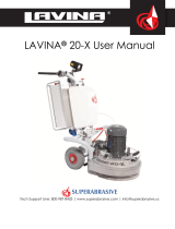
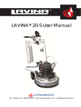
Machine characteristics
The Lavina 20® is made of two main component sections: carriage (1), which includes the frame, the
water tank, the electrical box and the controls; and the main head (2), which includes the motor, the base
plate and the 3 planetary heads with the tool holders.
Lavina 20® Main design
Figure 1
The two main component sections, the carriage and main head, are easy to disassemble, light to lift and
easy to ship.
The handle on the frame is adjustable in height and allows the operator to work in a correct and
safe posture.
The halogen spotlight attached to the frame enables the operator to work in darker areas.
Figure 2
Existing lighting system does not replace adequate overhead lighting. To
avoid accidents use the Lavina 20® only in well enlighten environment.
The frame itself is functioning as a vacuum hose and also acts as a connection between the
vacuum attachment hose and the two hoses coming out of the head base.
The controls are positioned on top of the electrical box and are easy to activate form the
operators working position.

Superabrasive Owner’s Manual – Lavina 20® 10/2022
Refers to Lavina 20® Lavina 20®E
6
Figure 3
The electrical box contains the electric switching devices and the inverter. The motor feeding
cable and the main feeding cable are plugged in the socket located on the bottom of the box.
The water tank is on the opposite side of the frame, so that the weight of the water has no
influence on the operation of the machine. The frame weight, on the other hand, is totally absorbed by
the driving wheels.
The self-leveling skirt is designed of a heavy material so that the skirt has contact with the
ground at all times regardless of the thickness of the tools used. The skirt adjusts its position depending
on the tool height used.
The motor is mounted on the base plate, and is driving the three planetary heads with a belt
system. Two of these heads have an opposite rotating direction, while the third head’s rotating direction
is responsible for rotating the whole planetary system. The three mounting plates could be floating
(flexible, and following the surface) or non-floating (rigid). Which plates are used depends on the work to
be done. A tool holder plate with a specially enclosed tool is mounted on each of the three mounting
plates. The Lavina 20 machine is a planetary movement machine. The planetary motion derives from the
friction between the tools and the floor, which is allowing the tools to spin in either clockwise or
counterclockwise direction. The design ensures that the tools will not force themselves against the
resistance of the floor surface. Instead, the machine will alternate directions to accommodate to a “high
spot” or a “low spot” imperfections in the floor without causing damage to the floor or the machine.
Technical Data
Working width
Tool holder diameter
Tool diameter
Tool holder rpm
Power
Total weight of machine
Grinding pressure
Poss. additional weight
Water tank capacity
Phases
Voltage/Hz
Amperage
Cable length
Machine LxWxH
Packing LxWxH
500mm 20”
3 x 165 mm 3 x 6,5”
3 x 225 mm 3 x 9”
300-1100 rpm
3 kW 4 hp
134 kg 295
62 kg 137 lbs
1 x 22 kg 48 lbs
16 l 4.2 gal
1
1x200/240 Volt 50/60Hz
14 Amps
17,4 m 57 ft
1350x540x1100 mm 53.1”x21.3 x43.3”
1160x730x1130 mm 45.7”x28.7”x44.5”

Superabrasive Owner’s Manual - Lavina 20® 10/2022
Refers to Lavina 20® Lavina 20®E
7
Environmental Conditions
The correct temperature range for operating the Lavina 20® is between 41°F and 86°F or 5°C and 30°C.
Never use the Lavina 20® during rain or snow when working outdoors. When working indoors, always
operate the machine in well ventilated areas.
Vibrations
The vibrations of the machine are within the limits of directive 2003/10/EC (the seventeenth individual
Directive of Article 16(1) of Directive 89/391/EC) when the Lavina 20® is operated with the recommended
tools and in normal conditions.
Sonorous Emissions
The sonorous emissions are, also within the limits of directive 2003/10/EC (the seventeenth individual
Directive of Article 16(1) of Directive 89/391/EC). However, as previously stated, the operator must wear
ear protectors.
Vacuum Connection
A connection for a vacuum dust extractor is located on the carriage. The Lavina 20® does not include a
vacuum dust extractor. The customer must purchase the vacuum dust extractor separately. The hose of
the vacuum extractor must be Ø 50 mm and can be glided over the pipe.
The vacuum dust extractor must be adapted for floor grinders and have a minimum air displacement of
20m3/h with a negative vacuum of 21 kPa.
Electrical Connection
The tension and power (ampere) are displayed on the electrical control box to avoid any incorrect
connection. Refer to these before connecting the power. To avoid electrical shocks, make sure the
ground power supply is functioning properly.
“CE“Certification
The Lavina 20® machine is designed to operate correctly in an electromagnetic atmosphere of industrial
type and is equipped with all the mechanical and electrical safety protections in conformity with the
following European CEE rules and regulations:
Directive machines 89/392-91/368-93/44-93/68 CEE
98/37 98/79 EC
Directive low tension 73/23 CEE
Directive Electro-magnetic compatibility 89/336 CEE
EN-292 part 1 en 2 (Machine safety)
EN-60204-1 (Electric equipment safety)
EN-60439-1 (Low tension electricity)
EN-50081-2 (Electromagnetic compatibility - Generic norm of emission - Part 2 - Ambient manufacturer /
(Electromagnetic compatibility - Generic emission standard - Industrial environment)
EN-50082-2 (Electromagnetic compatibility - Generic norm of Immunity - Part 2 - Ambient manufacturer /
(Electromagnetic compatibility - Generic emission standard - Industrial environment)
EN-55011 (CEI 110-6) (Limits and methods of measure of characteristics of radio disturb of industrial,
scientific and medical apparatuses (ISM)
EN-61000-4-2 / 4-4 / 4-6
EN 61800-3
Test results are a part of the machine’s technical information and can be sent upon a special request.
The machine is delivered with the CE mark exposed.
Label Data
The data on the label provides the correct voltage and kW (needed for operational purposes); weight
(needed for transportation purposes); production year and serial number (needed for maintenance
purposes).

Superabrasive Owner’s Manual - Lavina 20® 10/2022
Refers to Lavina 20® Lavina 20®E
8
Customer Service
For customer assistance and technical support call your local distributor or call Superabrasive Inc. at 1-
800-987-8403 or visit us at: www.superabrasive.com. If you misplace this manual, you can download it
from our website or call us and we will mail you a copy.
SAFETY DEVICES AND SAFETY INSTRUCTIONS
Recommended Use
The Lavina 20® machine is designed and manufactured to grind and polish concrete, terrazzo and natural
stone floors. It can be used for renovations as well as for polishing. The machine is designed for dry or
wet use. When using it dry, use a vacuum of appropriate size. For more information, please refer to the
chapter on handling the vacuum connection.
Prohibited Use
The machine MUST NOT be used:
For applications different than the ones stated in the General Description chapter.
For machining not-suitable materials.
In environment which:
o possess risks of explosion
o possess high concentration of powders or oil substances in the air
o possess risks of fire
o feature inclement conditions such as rainy or humid conditions.
o possess electromagnetic radiation
.
Danger
Make sure that:
you have closed the work area, so that no person unfamiliar with operating the machine can enter the
area
the tool plate and tools are adjusted to the machine properly
there are no missing parts of the machine
the machine is in upright working position
the protection devices are on their place.
the electrical cable is free to move and follow the machine easily. In order to keep the electrical cable
from being damaged, no vehicle must cross the zone where the electrical cable is situated.
Protection Devices
The machine is equipped with several protection devices including the following:
an emergency stop button
a protection skirt and a hood for protecting the tool plates.
These devices protect the operator and/or others persons from potential injuries. Do not remove them. On
contrary, before using the machine, please ensure that all protection devices are mounted and function
properly.

Superabrasive Owner’s Manual - Lavina 20® 10/2022
Refers to Lavina 20® Lavina 20®E
9
Arrest Functions
Functions of arrest of the machine are as follow:
Button to stop the motor (category 1)
Emergency button (category 1)
Safe Use
The Lavina 20® is designed to eliminate all risks correlated with its use. However, it is not possible to
eliminate the risks of eventual accident with the machine. Correlated residual risks may be caused by
unskilled or uninstructed operator. Such risks are:
Position Risks due to operator’s incorrect working position
Tangling up Risks due to wearing inappropriate working clothes
Training Risks due to lack of operational training
NOTE: In order to reduce all consequences of the above mentioned risks, we advise that machine
operators follow the instructions in the manual at all times.
Residual Risks
During the normal operating and maintenance cycles the operator is exposed to few residual risks, which
cannot be totally eliminated due to the nature of the operations.
Before You Begin
Working area must be clear from any debris or objects.
A first-time operator must always read the manual and pay attention to all safety instructions.
All electric connections and cables must be inspected for potential damages.
Ground wire system of the power supply must be also inspected.
Perform general daily inspections of the machine and inspect the machine before each use.
Always inspect the safety devices:
the emergency break must be clear and working
the tool protector must be working
the machine must be clean
Never operate the machine in the rain!
Confirm that there are no missing parts especially after transportation, repair or maintenance.
Before filling the water tank with water make sure the machine is not working and the main switch is
turned off.
Before turning on the machine make sure that the base is placed on the floor; the machine MUST NOT
be in an upright position when turned on!
Operating the Machine
When operating the Lavina 20®, make certain that there is no one, but you around the machine. Never
leave the machine unattended while working.
The electrical cable must move freely and must be damage-free.
The water hose must move freely and must be damage-free.
Check if the floor, you work on, is too uneven. If this is the case, it may damage the machine.
After Work is Completed
Clean the machine and its surroundings properly
Empty and clean the water tank
Unplug the machine and wind up the electrical cable
Store the machine in a safe place

Superabrasive Owner’s Manual - Lavina 20® 10/2022
Refers to Lavina 20® Lavina 20®E
10
The Work Area
Make certain that people or vehicle do not enter the work area.
Avoid cables and hoses being on the way.
Always check the floor for debris
Equipment
Always wear safety shoes when working with the machine.
Always wear ear protectors when working with the machine.
All personnel in the immediate work area must wear safety glasses with side shields.
Always wear safety gloves when changing the tools.
Always wear clothes suitable for the work environment.
Operator
Only one operator at a time can work with the machine.
The operator must be properly trained and well instructed prior to operating the machine.
The operator must understand all the instructions in this manual.
The operator must understand and interpret all the drawings and designs in manual.
The operator must know all sanitation and safety regulations pertaining to the operation of the Lavina 20®
machine.
The operator must know the machine’s work environment.
The operator must have floor grinding experience.
The operator must know what to do in case of emergency.
The operator must have an adequate technical knowledge and preparation.
HANDLING AND TRANSPORTATION
Preparing the machine for transportation
Unplug the motor cable plug from the control box and disconnect the water hose from the head by pulling
it out (Fig.4). Wind the electrical cable on the carriage (Fig.5). Release the pin sets that attaches the head
to the carriage (Fig.6). Pull out the water hose and the vacuum hoses, and dismount the head from the
carriage (Fig.7). The head of the Lavina 20® has one handle and one support intended for easy moving
and transportation (Fig. 8)
Figure 4
Figure 5
Figure 6

Superabrasive Owner’s Manual - Lavina 20® 10/2022
Refers to Lavina 20® Lavina 20®E
11
Figure 7
Figure 8
Transportation
The Lavina 20® is engineered with easy transportation in mind. The ability to dismantle the machine in two
parts adds to its convenient transportation and storage (Fig.9 and Fig.10)
Always store and transport the Lavina 20® in a dry place. Never transport the Lavina 20® unprotected; it
may be damaged if transported unprotected during rain or snow.
Figure 9
Figure 10
OPERATION
Preliminary Controls
Inspect the working area as explained in the safety instructions.
For wet use - fill in the water tank when the electrical cable is disconnected. Connect the vacuum
extractor to ensure that the vacuum hose is clear and it will follow the machine easily. Plug in the machine
and also make sure that the power cord is free to follow the working direction of the Lavina 20®.

Superabrasive Owner’s Manual - Lavina 20® 10/2022
Refers to Lavina 20® Lavina 20®E
12
Adjusting and Mounting Tools
Mount the tools only after ensuring that there is enough diamond bond material left. Be sure that the
plates are always clean before mounting. Always use the special key for mounting or adjusting, as seen
below Adjusting and mounting are shown on Fig.11.
Figure 11
Description of the Control Board
1 Digital RPM indicator: indicates the revolution per minute of the grinding plates (not the revolution per
minute of the entire unit).
2 Potentiometer: changes the RPM of the grinding plates.
3 Inverter alarm led: lights when the inverter goes into Alarm Mode.
4 Reset button: resets the alarm of the inverter
5 Forward/Reverse switch: chooses forward for clockwise rotation of the grinding plates or reverse for
anti-clockwise rotation of the grinding plates. (could be used to open up
diamond bond). By use of PCD plates check rotation direction!
6 ON button: starts the motor
7 Power led: lights when the power is on
8 OFF button: stops the motor
9 Emergency Switch: used in Emergency situations to put off the power completely
Figure 12

Superabrasive Owner’s Manual - Lavina 20® 10/2022
Refers to Lavina 20® Lavina 20®E
13
Starting the Machine
First, follow the directions in chapter Safety Devices and Safety Instructions.
Next, pull the emergency stop (9) to ensure that the machine is in working condition.
Check the potentiometer (2) and ensure that it is set at an approximate working speed.
If working wet, add water to the floor surface to prevent the tools from scratching the floor.
If working dry, omit this step, and instead, switch on the vacuum unit. Finally, hold the machine firmly and
push the start button (6).
Operating the Machine
Guide the machine in straight lines across the floor, and with each new line overlap a little bit of the
previously completed surface. Work at a constant speed allowing the tools time to work at a speed
appropriate for the tools’ grit size. Never stop the Lavina 20® machine in one spot while the tools are still
working because they will leave marks on the floor surface. When working wet, open the water tank
periodically to release water onto the floor surface. When working dry, check the floor surface periodically
to ensure that dust is not accumulating on the surface. Also, clean the vacuum if necessary.
Stopping the Machine
Stopping the machine must be done in a fluid movement. Do not stop the machine before arresting the
motor with the off button (8). Use only the in Emergency Switch button incase only in emergency or to
switch of power totally.
Remember not to hold the machine in one spot before turning off the motor as the tools could damage the
surface.
Alarm
Alarm light (3) will light incase inverter goes in alarm mode, most common is overloading motor. To reset
the mode push reset button (4). See chapter troubleshooting for meaning of alarm displays
TOOLS AND ACCESSORIES
Weights
Superabrasive offers an additional weight for increasing the productivity of the machine (Fig.13). An
additional weight weighs about 48 lbs or 22 kg. Each individual application, type and condition of surface,
power capacity of the outlet, etc. will determine the use of a weight. The weight stacks onto three nylon
posts around the outer bowl (Fig.14).
The additional weight depend on the tools, it is not always possible to add a weight. Some tools work too
aggressively and the machine can stop.
Order number for weight A07.00.00.00
Figure 13
Figure 14

Superabrasive Owner’s Manual - Lavina 20® 10/2022
Refers to Lavina 20® Lavina 20®E
14
Tool holder key
It is used for adjusting, mounting and
dismounting of the tools. Always use the
special key for mounting. I
Order number is A03.00.00.00
Figure 15
Belt replacing tool
You need this tool when you want to replace
the belt. It is explained below in chapter
Troubleshooting.
This tool can be ordered with number
L20SPS-00.00.01.00
Figure 16

Superabrasive Owner’s Manual - Lavina 20® 10/2022
Refers to Lavina 20® Lavina 20®E
15
Floating back up plate
It is usually ordered as Assembly. Only items on pos. 1, pos. 2, pos. 3 and pos. 4 can be ordered
as spare parts.
A floating back up plate is mounted on each of the three planetary heads. Its advantage is that it has
elastic shock absorbers which enable the tool plate to float and follow the surface profile.
A tool can be attached to this floating with use of the tool holder key.
The item is number is A01.00.00.00.
Figure 17
Figure
№
Item
Description
Quantity
Fig.17 L20®
1
A01/00.00.01
Shock absorber
4
Fig.17 L20®
2
A01/00.00.02
Sealer front
1
Fig.17 L20®
3
A01/00.00.03
Flange
1
Fig.17 L20®
4
М6х20 DIN7991
Screw
4
Fig.17 L20®
5
М6х10 DIN7991
Screw
2
Fig.17 L20®
6
d6х10 DIN1481
Dowel spring
2
Fig.17 L20®
7
LMKAS32BA01/00.00.07
Spring ring
1
Fig.17 L20®
8
М4х10 DIN7991
Screw
4
Fig.17 L20®
9
A01/00.00.09
Key-lock
1
Fig.17 L20®
10
A01/00.00.10
Key-lock holder
1
Fig.17 L20®
11
A01/00.00.11
Retainer
1
Fig.17 L20®
12
A01/00.00.12
Disc
1
Fig.17 L20®
13
SKF DIN5401
Sphere
2

Superabrasive Owner’s Manual - Lavina 20® 10/2022
Refers to Lavina 20® Lavina 20®E
16
Rigid Back up plate
It is ONLY ordered as Assembly.
The tool plates attached on the three planetary heads can be non-floating (rigid), as well. These tools are
more recommended for flat grinding work, without following the surface.
These tool plates can be ordered upon request with number A02.00.00.00
Figure 18
Figure
№
Item
Description
Quantity
Fig.18 L20®
1
A02/00.00.01
Flange upper
1
Fig.18 L20®
2
LMKAS32BA01/00.00.07
Spring ring
1
Fig.18 L20®
3
A02/00.00.03
Flange down
1
Fig.18 L20®
4
A02/00.00.04
Disc
1
Fig.18 L20®
5
М8х20 DIN7991
Screw
4
Fig.18 L20®
6
d6х10 DIN1481
Dowel spring
2
Fig.18 L20®
7
М6х10 DIN7991
Screw
2
Fig.18 L20®
8
SKF DIN5401
Sphere
2
Fig.18 L20®
9
М4х10 DIN7991
Screw
4
Fig.18 L20®
10
A01/00.00.11
Retainer
1
Fig.18 L20®
11
A01/00.00.09
Key-lock
1
Fig.18 L20®
12
A02/00.00.12
Bushing for absorber
4
Fig.18 L20®
13
A02/00.00.13
Absorber
4
Fig.18 L20®
14
М8х25 DIN933
Bolt
4
Fig.18 L20®
15
A01/00.00.10
Key-lock holder
1
Fig.18 L20®
16
М10х50 DIN912
Screw
2
Fig.18 L20®
17
10.7-1081
Washer Nord Lock NL10
2
Fig.18 L20®
18
М8 DIN125А
Washer
4

Superabrasive Owner’s Manual - Lavina 20® 10/2022
Refers to Lavina 20® Lavina 20®E
17
SPARE PARTS
Lavina 20® Assembly and parts specification
Figure 19
Figure
№
Item
Description
Quantity
Fig.19 L20®
1
Main head
1
Fig.19 L20®
2
L25SPS-07.03.00.00
Pin assembly
2
Fig.19 L20®
3
L20SPS-00.00.00.10
Vacuum hose
2
Fig.19 L20®
4
D9L74
Water hose
1
Fig.19 L20®
5
М8х25DIN912
Screw
4
Fig.19 L20®
6
L20SPS-02.00.00.00
Carriage
1
Fig.19 L20®
7
М8 DIN125A
Washer
4
Fig.19 L20®
8
M8 DIN127B
Washer
4
Fig.19 L20®
9
М8 DIN934
Nut
4

Superabrasive Owner’s Manual - Lavina 20® 10/2022
Refers to Lavina 20® Lavina 20®E
18
Lavina 20® Assembly and parts specification of the main head
Figure 20
Figure
№
Item
Description
Quantity
Fig.20 L20®
1
L20SPS-00.00.00.35
Disc
1
Fig.20 L20®
2
L20SPS-06.00.00.00
Pulley unit
3
Fig.20 L20®
3
L20SPS-00.06.00.00
Roller unit
2
Fig.20 L20®
4
L20SPS-00.00.00.43
Balancing roller
1
Fig.20 L20®
5
L25SPS-00.00.00.50
Extended bolt
3
Fig.20 L20®
6
M16 DIN125A
Washer
6
Fig.20 L20®
7
M16 DIN127B
Spring washer
6
Fig.20 L20®
8
M16 DIN934
Nut
3
Fig.20 L20®
9
M16 DIN439B
Low nut
3
Fig.20 L20®
10
TC-35/ER1775x30x2,5
Flat belt
1
Fig.20 L20®
11
L25SPS-00.00.00.36
Shaft
1
Fig.20 L20®
12
6006-2Z
Spherical rollers
1
Fig.20 L20®
13
A55 DIN472
Retaining ring
1
Fig.20 L20®
14
A100 DIN472
Retaining ring
1
Fig.20 L20®
15
6013-2Z
Spherical rollers
2
Fig.20 L20®
16
L25SPS-00.00.00.34
Ring
1
Fig.20 L20®
17
L25SPS-00.00.00.23
Ring compensating
1
Fig.20 L20®
18
B65 DIN471
Retaining ring
1
Fig.20 L20®
19
L20SPS-00.00.00.02
Sealing cap
1
Fig.20 L20®
20
M6x16 DIN7991
Screw
4

Superabrasive Owner’s Manual - Lavina 20® 10/2022
Refers to Lavina 20® Lavina 20®E
19
Fig.20 L20®
21
L20SPS-00.00.00.08
Central pulley
1
Fig.20 L20®
22
L25SPS-00.00.00.15
Front Washer
1
Fig.20 L20®
23
DIN 6885A 8x7x36
Key
1
Fig.20 L20®
24
L20SPS-00.02.00.01
Cover
1
Fig.20 L20®
25
L25SPS-00.02.00.02
Flange
3
Fig.20 L20®
26
L25SPS-00.00.00.24
Glide seal
3
Fig.20 L20®
27
L25SPS-00.00.00.25
Cap ring
3
Fig.20 L20®
28
B80 DIN471
Retaining ring
3
Fig.20 L20®
29
M6x10 DIN967
Screw
3
Fig.20 L20®
30
M5x10 DIN933
Bolt
12
Fig.20 L20®
31
M5 DIN125A
Washer
12
Fig.20 L20®
32
M4x6 DIN967
Screw
12
Fig.20 L20®
33
L20SPS-07.01.00.00
Base plate
1
Fig.20 L20®
34
L25SPS-07.00.00.06
Fitting for water
1
Fig.20 L20®
35
L20SPS-03.00.00.00
Machine support
1
Fig.20 L20®
36
M8 DIN127B
Spring washer
14
Fig.20 L20®
37
M8x20 DIN912
Screw
14
Fig.20 L20®
38
M8x25 DIN7991
Screw
2
Fig.20 L20®
39
M6x16 DIN7991
Screw
3
Fig.20 L20®
40
L25SPS-07.00.00.35
Seal cap
1
Fig.20 L20®
41
L20SPS-08.00.00.00
Handle
1
Fig.20 L20®
42
L20SPS-07.00.00.01
Support
2
Fig.20 L20®
43
L25SPS-07.00.00.02-L
Left fork
1
Fig.20 L20®
44
L25SPS-07.00.00.02-R
Right fork
1
Fig.20 L20®
45
L20SPS-07.00.00.02
Front weight holder
1
Fig.20 L20®
46
M10 DIN125A
Washer
4
Fig.20 L20®
47
M10 DIN127B
Washer spring
4
Fig.20 L20®
48
M10x25 DIN912
Screw
4
Fig.20 L20®
49
L25SPS-07.00.00.05
Back weight holder
2
Fig.20 L20®
50
L20SPS-00.00.00.09
El. Motor AT100 L2 3000 rpm
(until May 2009)
1
Fig.20 L20®
50
L20SPS-00.00.00.09-01
El. Motor AT100 L4 1450 rpm
1
Fig.20 L20®
51
M12 DIN125A
Washer
4
Fig.20 L20®
52
M12 DIN127B
Spring washer
4
Fig.20 L20®
53
M12x30 DIN933
Bolt
4
Fig.20 L20®
54
L20SPS-04.00.00.01
Cover
1
Fig.20 L20®
55
L25SPS-04.01.00.00
Vacuum port
2
Fig.20 L20®
56
M5x16 DIN84A
Screw
4
Fig.20 L20®
57
L20SPS-05.00.00.00
Guard assembly
1
Fig.20 L20®
58
M6x14 DIN967
Screw
4
Fig.20 L20®
59
M5 DIN125A
Washer
4
Fig.20 L20®
60
M5 DIN127B
Spring washer
4
Fig.20 L20®
61
M5 DIN934
Nut
4
For L500 (Europe) position. 54 Cover is with number L20SPS-04.00.00.01-01,
For L500 (Europe) position 57 is with number L20SPS-05.00.00.00-01.

Superabrasive Owner’s Manual - Lavina 20® 10/2022
Refers to Lavina 20® Lavina 20®E
20
Lavina 20® Assembly and parts specification of the pulley units
Figure 21
Lavina 20® Assembly and parts specification of the guard assembly
Figure 22
Figure
№
Item
Description
Quantity
Fig.22 L20®
1
L20SPS-05.00.00.02
Guard
1
Fig.22 L20®
2
L20SPS-05.00.00.01
Ring
1
Fig.22 L20®
3
M5 DIN9021A
Washer
18
Fig.22 L20®
4
d4x10 DIN7337
Rivet
18
/