Page is loading ...

Installation and Operating Manual
Battery Protector 100 Switching Capacity 12 V-24 V / 100 Amperes No. 3078
Please read the Safety Regulations, mounting instructions and operating manual completely prior
to starting connection and start-up.
Fully automatic battery protection for intervention vehicles, high-quality campers and the marine field.
The battery protector 100 is connected between supply battery and consumer loads. It protects the battery from dangerous
deep discharge and the consumer loads from low voltage as well as from overvoltage.
Note: The values being indicated in parentheses ( ) apply to 24 V operation.
Functions:
• The unit protects the battery from dangerous deep discharge.
• Maximum admissible current 100 A; thus, it is also suitable for high-capacity consumer loads.
• Suitable for any type and brand of lead batteries (Acid, Gel, Dryfit, Heavy Duty, Solar, fleece, AGM etc.). The automatic
switching threshold ensures an additional protection against latent consumer loads.
• Suitable for lithium batteries LiFePO4.
• Disconnection of the consumer loads for protection against dangerous overvoltage.
• The disconnection can be cancelled manually by means of the "EMERGENCY-ON" function.
• It can also be used as efficient, remote-controlled main-switch with battery control.
• Full remote control with external single-pole remote switch is possible.
• Preliminary alarm as soon as the switch-off level is reached.
• Visual indication of the operating state.
• Audible indication in case of preliminary alarm and disconnection (can be deactivated, optionally).
• Output for external alarm indication (max. 0.2 A short circuit-proof).
• Input for separate sensor line for unfalsified measurement of the battery voltage.
• Immediate emergency shut-down in case of defective battery or extremely discharged battery.
• Least own electricity consumption during operation (acc. to EN13976).
• No own electricity consumption in case of disconnection by external remote switch.
Installation:
1. Choose an installation place being clean and being protected from humidity and dust.
2. The installation place of the unit should be chosen in such a way, that the cables of battery and consumer loads can
be as short as possible (losses) to ensure that the push-button "EMERGENCY" is easily accessible.
3. Fasten the unit securely with screws at the casing flanges. The unit can be installed in any position.
4. In case of great distance to the battery, we recommend to connect a separate sensor cable.
5. The cable lugs of the connection cables for battery and load should be connected solidly to the terminal lugs
"Battery" and "Load" by means of the delivered screws M6. Recommended tightening torque approx. 6-7 Nm.
The enclosed protection cover must be installed as short-circuit protection for this area.
6. Observe to fasten the connection cables in such a way, that neither high tensible force, nor high force of pressure is
acting on the terminal lugs.

- 2 -
Connection:
Always disconnect the power supply to the battery prior to working on the electric system to avoid
short circuit!
It is recommendable to use connection cables of different colours to avoid malfunctions due to mixed up
connections.
• The unit will not be damaged by wrong polarity, but it will not be operating.
• Strictly observe the cable cross-sections. The power cable must be as short as possible. Observe the
polarity.
• Insert fuses as cable protection near the battery.
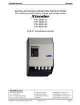
Connection Plan:
[R1]
• Position the fuses for protection of the cables as close as possible to the battery,
for instance Votronic power fuse holder.
• The charging sources (mains supply charger, solar controller, generator, charging converter etc.) are
connected directly to the battery to ensure battery charging, even with switched-off battery protector.
• Powerful inverters with own low voltage disconnection are also connected directly to the battery.
Option: Operation with Sensor Line "Sensor +"
Selector Switch 6: "Sens. Set Batt." to position "ON" ( - ) .
Particularly in case of powerful consumer loads being equipped with long charging cables, it is recommendable to measure the
battery voltage unfalsified via a "sensor line" directly at the battery. This allows a more precise observation of the charging
voltage rates for connection and disconnection of the battery.
The correct installation of the sensor line is directly at the positive pole (+) of the battery, and never at a distribution or the
like.
The same applies to the minus supply. Connect the cable "Battery –" directly to the battery.

- 3 -
Operation without sensor cable: Set the selector switch 6 "Sens. Batt." to position "OFF" ( X ).
Terminal "Sensor +" is left free
Option: Remote Switch
The unit can be used as remote-controlled battery main switch with battery protection by insertion of a simple switch into
the sensor line "Sensor +".
Its function is identical to the key "EMERGENCY ON/OFF" (see below) with preliminary alarm, EMERGENCY ON etc.
Activation of the EMERGENCY-ON function is effected by switching-off the switch for 1 second and switching it on again.
Option: Output "Alarm"
It is possible to connect an external alarm indication up to 0.2 A at the terminal alarm.
The output will be active in case of: Preliminary alarm, disconnection of the relay by low voltage or overvoltage recognition.
In case of manual disconnection by means of the key or the remote switch, also the alarm output will be switched-off.
Function:
If the battery voltage drops to the adjusted disconnection voltage, a preliminary alarm will be released:
• The red LED "OFF" is flashing.
• The audible alarm beeper sounds, provided it had been activated by means of switch 4.
• The alarm output will be active.
This allows the user to switch-off redundant consumers to avoid release of the low voltage disconnection. If the battery had
been relieved appreciably after that, the preliminary alarm will be reset.
If a low voltage disconnection had been released for all that, restart can be effected:
• Automatically according to the connection voltage rates, which are listed in the table (charging mode) or
• Manually at any time by means of the key EMERGENCY ON / OFF or remote switch OFF and again ON.
Key EMERGENCY ON/OFF:
The laterally installed key allows the following functions:
1. Main Switch Function
The unit can be used as powerful battery main switch with battery protection.
During the standard operation, the connected consumer loads can be switched-on and -off by means of this key at any time.
2. EMERGENCY ON Function
If the unit had been switched-off by dropping below the disconnection voltage, this key can be used to restart important
consumer loads in case of emergency.
If the disconnection voltage will be reached again, the Battery Protector 100 will automatically be switched-off again with the
corresponding delay and preliminary alarm.
Display of the Switching Position of the Relay:
The mechanical position of the built-in side-stable relay OFF/ON is shown in the display window "Relay manually".
"Relay Manually OFF/ON"
In case of an absolute emergency situation the low residual capacity of the battery can be still used by placing the side-stable
relay to position "ON" using a small screw-driver.
Warning:
o After that, there will be no automatic disconnection after 40s!
o The battery might be totally discharged!
o Recharge the battery as soon as possible!

- 4 -
Selection of the selector switches, the switching voltages
and of the operating mode:
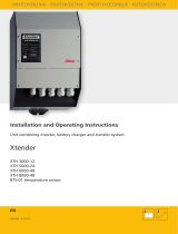
Six (6) selector switches are located at the unit rear. Move the white levers vertically to the desired position:
Switches 1 and 2: for optionally 3 fixed switching thresholds or automatic switching threshold (lead)
Switch 3: Board Supply Voltage: 12 V ( ▼ ) or 24 V ( ▲ )
Switch 4: Audible Alarm (Beep) desired: ON ( ▼ ) or OFF ( ▲ )
Switch 5: Not assigned, always in position ( ▲ )
Switch 6: Sensor Line "Sensor +" (Option): ON ( ▲ ) or OFF ( ▼ ) see page 3
Figure shows the factory-adjustment of the switches:
1 and 2: Disconnection Voltage: Automatic Switching Threshold
1 and 2: Connection Voltage: 12.5 V
3 Board Supply Voltage: 12 V
4 Audible Alarm: active
5 Not used: always (▲)
6 Sensor Line: Operation without
sensor line
Table Selector Switches 3, 2 and 1:
Selectable switching thresholds with delay times or automatic switching threshold:
3 2 1
Disconnection Voltage 24 V Connection Voltage
▲
▲
▲
21.2 V / 40 s 24.8 V / 1 s
▲
▲
▼
23.0 V / 40 s 25.0 V / 1 s
▲
▼
▲
23.6 V / 40 s* 25.6 V / 1 s*
▲
▼
▼
Automatic 25.0 V / 2 s
3 2 1
Disconnection Voltage 12 V Connection Voltage
▼
▲
▲
10.6 V / 40 s 12.4 V / 1 s
▼
▲
▼
11.5 V / 40 s ++ 12.5 V / 1 s ++
▼
▼
▲
11.8 V / 40 s * + 12.8 V / 1 s * +
▼
▼
▼
Automatic 12.5 V / 2 s
The unit can extend the lifetime of Lithium LiFePO4 batteries, if it had been set in such a way, that it
switches off before the BMS safety system against low voltage of the battery acts.
For lithium batteries, the unit is not suitable as substitute for a BMS safety system of the battery!
++ Lithium LiFePO4 batteries, recommended for high load
+ Lithium LiFePO4 batteries, recommended for low or moderate load
* Switching thresholds according to DIN EN 1789, starter batteries: Warning the driver of a battery,
which is not capable to start (such as for intervention vehicles with only one battery circuit) and of the
disconnection of additional consumer loads at this battery circuit.

- 5 -
Function of the Automatic Switching Threshold:
The intelligent automatic switching threshold is adapted to lead batteries (acid, gel, Dryfit, AGM, Heavy Duty,
solar, fleece etc.) with their comparatively "smooth" voltage characteristic lines.
It is not suitable for lithium LiFePO4 batteries with their discharge characteristic lines starting flat and dropping
steeply after that. In this case, use one of the recommended fixed switching thresholds.
For batteries in lead technology the intelligent automatic switching threshold allows the maximum use of the battery
capacity and ensures protection of the battery at the same time. It is ideal for
• very large consumers in the range of seconds, minutes.
• average consumers in the range of minutes, hours
• small consumers in the range of hours, days, weeks
• latent micro-consumers in the range of several weeks
• all combinations of these operating modes in practical use.
The automatic switching threshold continuously determines the parameters for the correct disconnection voltage and the
time.
If a battery is permanently discharged with only small current rates, disconnection must be effected in case of higher voltage
levels.
By this method, the cells are protected from degenerative changes and lasting damages at the electrodes.
The disconnection will be effected at 12.2 V in 4 weeks.
Consumer loads with large current draw will cause a quick drop of the battery voltage. Full exploitation of the battery
capacity requires a lower disconnection voltage, which is determined continuously by the battery protector on the basis of
the integrated lead battery characteristic values.
If large consumers are not used, the battery voltage will rise again and also the battery protector will rise the disconnection
voltage by and by.
A preliminary alarm of 40 s (LED "OFF", beeper and alarm output) will be given prior to disconnection also in the automatic
mode.
Restarting is also effected with the automatic switching threshold:
• Automatically according to the connection voltage rates, which are listed in the table (charging mode) or
• Manually at any time by means of the key EMERGENCY ON/OFF or remote switch OFF and again ON.

- 6 -
Pilot Lamps:
The two LEDs of the display are indicating the operating state by different flashing cycles.
The display window "Relay manually" shows the switch position of the relay "ON/OFF" for control.
Operating State LED "ON"
(green)
LED "OFF"
(red) Beep Switch Position
of the Relay Alarm Output
Normal operation,
Output "Load +" On
LED is flashing - - ON not active
Preliminary alarm
voltage is reached - LED is flashing Audible signal ON Output activated
switched-off by
U Bat. < disconnection
voltage
- LED is flashing Audible signal
every 40 s OFF Output activated
Disconnection by
Overvoltage
U Bat > U Max
LED is flashing
LED is flashing Audible signal
every 40 s OFF Output activated
No operating voltage - - - OFF not active
Manual disconnection by
ON/OFF key - - - OFF not active
Supply of the
operating voltage/
Sensor +
-
LED is fast
flashing - OFF -> ON not active
Operating Instructions:
• Overvoltage Limitation:
Sensitive consumers are protected by disconnection of the supply voltage at 15.5 V (31.5 V). Reconnection is effected
20 seconds after a drop below this voltage level.
If such high voltage levels will be reached repeatedly, the charging controller, the battery, the charger and the battery
terminals should be checked.
• Lifetime of the battery:
The battery protector 100 can extend the lifetime of the battery considerably. The following general rules must be
observed:
Keep batteries as cool as possible; choose an appropriate location for installation and observe the instructions of the
manufacturer.
Especially batteries on lead basis:
In case of doubt, partially discharged batteries are to be charged fully as soon as possible.
Store only fully charged batteries and recharge them periodically, particularly in case of used (older) batteries and
higher temperatures. Sulphation of the battery plates due to deep discharge is to be prevented by immediate charging,
particularly in case of low and high ambient temperatures.

- 7 -
Declaration of Conformity:
In accordance with the provisions of Directives 2014/35/EU, 2014/30/EU, 2009/19/EC, this
product complies with the following standards or normative documents:
EN55014-1; EN55022 B; EN61000-6-1; EN61000-4-2; EN61000-4-3; EN61000-4-4;
EN62368-1; EN50498.
The product
must not be
disposed of in
the household
waste.
The product is RoHS compliant.
It complies with the directive
2015/863/EU for Reduction of
Hazardous Substances in electrical
and electronic equipment.
Safety Regulations:
The Battery Protector 100 had been designed according to the valid safety regulations.
Appropriate application is restricted to:
• Deep discharge protection for batteries with the specified nominal voltage.
• The indicated voltage rates, current rates and cable cross-sections of the cabling.
• Installation of the indicated fuses near the battery to protect the cabling of the unit.
• Technically faultless condition.
• Installation in a well-ventilated room, protected from rain, humidity, dust, aggressive battery gases, as well as in
an environment being free from condensation water.
• For lithium batteries, the unit is not suitable as substitute for a BMS safety system of the battery!
• The unit is not applicable as safety relay (emergency off switch) for disconnection of dangerous machines or
drives.
• Never connect the unit between starter battery and the electric/electronic system of the vehicle.
• Never use the unit in locations where the risk of gas or dust explosion exists!
• Observe the safety regulations.
• Open-air operation of the unit is not allowed.
• Cables are always to be laid in such a way that damage is excluded. Observe to fasten them tightly.
• Never lay 12 V (24 cables and 230 V mains supply cables into the same cable conduit (empty conduit).
• Check live cables or leads periodically for insulation faults, points of break or loosened connections. Occurring
defects must be remedied immediately.
• The unit is to be disconnected from any connection prior to execution of electrically welding or work on the electric
system.
• If the non-commercial end-user is not able to recognize the characteristic values being valid for a unit or the
regulations to be observed, a specialist is always to be consulted.
• The user/buyer is obliged to observe any construction and safety regulations.
• The unit is not equipped with parts, which can be replaced by the user.
• Keep children away from batteries and connections.
• Observe the safety regulations of the battery manufacturer.
• Ventilate the battery room.
• Non-observance may result in injury or material damage.
• The warranty period is 36 months from the purchase date (against presentation of the sales slip or invoice).
• The warranty will be void in case of any inappropriate utilisation of the unit, if it is used beyond the technical
specification, in case of improper operation or external intervention. We do not assume any liability for any damage
resulting hereof. The liability exclusion is extended to any service being executed by third, which has not been
ordered by us in writing. Service is to be effected exclusively by VOTRONIC Lauterbach.

- 8 -
Technical Data:
Nominal Operating Voltage (DC) 12 V or 24 V (switchable)
Operating Voltage Range (DC) 8.5 V - 40 V
Current Consumption ON < 3 mA
Current Consumption OFF < 3 mA
Current Consumption ON by Remote Control Switch < 3 mA
Current Consumption OFF by Remote Control Switch 0 mA
Load Output +:
Max. Admissible Current 100 A Continuous, 150 A 10 Sec., max. 180 A
Short-circuit-proof and overload-proof according to IEC and DIN EN 61036 / 61037
Tightening Torque Connection Screws,
Recommended 6 - 7 Nm
Voltage Rates Connection and Disconnection: See Page 4, Table Selector Switch 3, 2 and 1
Overvoltage Disconnection 12 V > 15.5 V 2 sec.
Overvoltage Disconnection 24 V > 31.5 V 2 sec.
Return When dropping below the voltage rates, delay 20 sec.
Alarm Output:
Execution Open Collector Hi-Side (+ switching "PNP"), maximum 0.2 A
Internal fuse 1 A, self-resetting after disconnection of the
consumer
Output Voltage During Alarm (active) 12 V, 24 V (Voltage at terminal "Battery" minus approx. 0.3 V)
Output Voltage without Alarm (not active) 0 V
Fitting Position of Unit any
Working Temperature Range -20/+45 °C
Protection Class IP2X
Dimensions (mm) 100 x 89 x 35 mm
Weight 175 g
Ambient Conditions, Humidity of Air max. 95 % RH, no condensation
Declaration of Conformity:
In accordance with the provisions of the statutory requirements and the relevant directives, Electrical
Equipment (Safety) Regulations 2016, Electromagnetic Compatibility Regulations 2016, The Restriction of the
Use of Certain Hazardous Substances in Electrical and Electronic Equipment Regulations 2012 this product
complies with the following standards or normative documents:
EN55014-1; BS EN61000-6-1; BS EN61000-4-2; BS EN61000-4-3; BS EN61000-4-4; BS EN62368-1; BS EN60335-
2-29; BS EN50498, BS EN IEC 63000.
Recycling:
At the end of its useful life, you can send us this device for professional disposal:
You can find more information about this on our website at www.votronic.de/recycling
Delivery Scope:
• Battery Protector 100
• Protection Cover for Power Connections
• 2 Screws M6 for Capacity Terminal Lugs
• Operating Manual
Subject to misprints, errors and technical modification without notice.
All rights reserved. This material may not be published, broadcast, rewritten or redistributed in whole or part without the
express written consent of the manufacturer. Copyright VOTRONIC 11/2022.
Made in Germany by VOTRONIC Elektronik-Systeme GmbH, Johann-Friedrich-Diehm-Str. 2, 36341 Lauterbach/Germany
Phone: +49 (0) 6641/91173-0 Fax: +49 (0) 6641/91173-10 E-mail: info@votronic.de Internet: www.votronic.de
/