Page is loading ...

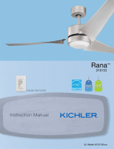
INSTRUCTION MANUAL
Model# 300032, 300154
Product images may vary slightly from actual product.
48”/ 54” Volos LED
READ AND SAVE THESE INSTRUCTIONS

2 | KICHLER.COM
TABLE OF CONTENTS
SAFETY RULES ..................................................................3
TOOLS REQUIRED ...........................................................5
PACKAGE CONTENTS ...................................................5
MOUNTING OPTIONS ....................................................6
HANGING THE MOTOR ASSEMBLY ......................... 7
INSTALLATION OF SAFETY CABLE ..........................8
ELECTRICAL CONNECTIONS ................................... 9
WIRE DIAGRAM ...............................................................10
FINISHING THE MOTOR INSTALLATION ............. 11
INSTALLING THE MOTOR HOUSING ....................12
ATTACHING THE FAN BLADES .................................13
INSTALLING THE LED LIGHT KIT ASSEMBLY ....13
INSTALLING THE WALL CONTROL .........................14
OPERATING INSTRUCTION ........................................15
TROUBLESHOOTING....................................................17
FCC INFORMATION .......................................................18

48”/ 54” Volos LED | 3
SAFETY RULES
CAUTION – RISK OF SHOCK – Disconnect Power at
the main circuit breaker panel or main fusebox before
starting and during the installation.
WARNING: All wiring must be in accordance with the
National Electrical Code “ANSI/NFPA 70” and local
electrical codes. Electrical installation should be
performed by a qualified licensed electrician.
WARNING: To reduce the risk of electric shock, this fan
must be installed with a general-use, isolating wall
control/switch.
WARNING: Not suitable for use with solid-state speed
controls.
WARNING: To reduce the risk of fire, electric shock, or
personal injury, mount to outlet box marked
“acceptable for fan support of 15.9 kg (35 lbs.) or less”
and use mounting screws provided with the outlet box.
Most outlet boxes commonly used for the support of
light fixtures are not acceptable for fan support and
may need to be replaced. Due to the complexity of the
1.
2.
3.
4.
5.
installation of this fan, a qualified licensed electrician is
strongly recommended.
The outlet box and support structure must be securely
mounted and capable of reliably supporting a minimum
of 15.9 kg (35 pounds). Use only cULus Listed outlet
boxes marked “Acceptable for Fan Support of 15.9 kg
(35 lbs) or less”.
The fan must be mounted with a minimum of 2.1 m
(7 feet) clearance from the trailing edge of the blades
to the floor.
To operate the reverse function on this fan, press the
reverse button while the fan is running.
Avoid placing objects in the path of the blades.
WARNING: make sure the power is disconnected
before cleaning your fan.
To avoid personal injury or damage to the fan and
other items, be cautious when working around or
cleaning the fan.
6.
7.
8.
9.
10.
11.

4 | KICHLER.COM
WARNING
TO REDUCE THE RISK OF PERSONAL INJURY, DO NOT BEND
THE BLADE DURING ASSEMBLY OR AFTER INSTALLATION.
DO NOT
INSERT OBJECTS IN THE PATH OF THE BLADES.
SAFETY RULES
Do not use water or detergents when cleaning the fan
or fan blades. A dry dust cloth or lightly dampened
cloth will be suitable for most cleaning.
After making electrical connections, spliced
conductors should be turned upward and pushed
carefully up into outlet box. The wires should be spread
apart with the grounded conductor and the
equipment-grounding conductor on one side of the
outlet box and the ungrounded conductor on the other
side of the outlet box.
Electrical diagrams are reference only. Light kits that
are not packed with the fan must be cULus Listed and
marked suitable for use with the model fan you are
installing. Switches must be cULus General Use
Switches. Refer to the Instructions packaged with the
light kits and switches for proper assembly.
All set screws must be checked, and retightened where
necessary, before installation.
12.
13.
14.
15.
The subject fan weight information is as below:
16.
Model
300032
300154
Net Weight
(kgs)
Gross Weight
(kgs)
Net Weight
(lbs)
Gross Weight
(lbs)
6.9 7.7 15.216.9
7.3 8.4 16.06 18.48

TOOLS REQUIRED
PACKAGE CONTENTS
Phillips screwdriver
Blade screwdriver
11 mm wrench
Step ladder
Wire cutters
Unpack your fan and check the contents . You should have the following items:
A. Mounting Plate
B. Motor Assembly
C. Motor Housing
D. LED Light Kit Assembly
E. Blade (3)
F. Wall Control System
Receiver (1)
Wire connector (6)
Wall Control (1)
Wire connector (4)
Screw ( 2)
G. Package hardware
1.) Mounting hardware:
Wire Connector (3)
2.) Blade attachment hardware:
Screw (9)
3.) Safety cable hardware:
Wood screw (1),
Spring washer (1)
Flat washer (1)
A
B
C
D
GF
E
48”/ 54” Volos LED | 5

6 | KICHLER.COM
MOUNTING OPTIONS
If there isn’t an existing UL (cUL for Canadian Installation) listed mounting box,
then read the following instructions. Disconnect the power by removing fuses
or turning o circuit breakers.
Secure the outlet box directly to the building structure. Use appropriate
fasteners and building materials. The outlet box and its support must be able
to fully support the full weight of the fan (up to 15.9 kg (35 pounds)). Do not use
plastic outlet boxes.
Figures 1 and 2 are examples of dierent ways to mount the outlet box.
NOTE: Depending on the location you have selected for installation, you may
need to purchase and install a “Joist Hanger” for the support of the outlet box.
Make sure the joist hanger you purchase has been designed for use with ceiling
fans. (Fig. 3)
Fig. 1
Outlet box
Outlet box
Fig. 2
Fig. 3
Outlet box

Fig. 4
Fig.5
HANGING THE MOTOR ASSEMBLY
REMEMBER to turn off the power before you begin installation.
This is necessary for your safety and also the proper programming
of the control system.
To properly install your ceiling fan, follow the steps below.
Step 1. Before attaching fan to outlet box (not included), ensure the
outlet box is securely fastened to at least two points to a structural
ceiling member (a loose box will cause the fan to wobble). Pass the
120 volt supply wires from the outlet box through the center of the
mounting plate. Install mounting plate to outlet box in ceiling using the
screws and washers included with the outlet box. (Fig. 4)
Step 2. Hook the motor assembly onto the mounting plate as shown.
You can now proceed with the electrical wiring of your fan. (Fig.5)
Outlet Box
Screw
Washer
Motor
Assembly
Mounting Plate
Mounting Plate
48”/ 54” Volos LED | 7

8 | KICHLER.COM
Flat Washer
INSTALLATION OF SAFETY SUPPORT
(required for Canadian installation ONLY)
A safety support cable is provided to help prevent the ceiling fan from faIling, please
install it as follows.
Step 1. Drive a wood screw and washers into the side of the brace that holds the outlet
box. Leave 3mm (1/8") of space between the support brace and the washer. (Fig. 6)
Step 2. Insert the safety cable through the mounting bracket and one of the holes in
the outlet box into the ceiling. Adjust the length of the safety cable to reach the screw
and washers by pulling the extra cable through the cable clamp until the overall length is
correct, put the end of the cable back through the cable clamp, forming a loop at the end
of the cable. Tighten the cable clamp securely. Now, put the loop in the end of the safety
cable over the wood screw and under the washer. Tighten the wood screw securely.
(Fig.7)
NOTE: Although the safety support cable is required for Canadian installations only.
It’s a good idea to make the attachment with any installation.
Wood Screw
Spring Washer
Outlet Box
Ceiling
Support Brace
Safety Cable Bolt
Wood Screw
Fig. 6
Fig. 7

ELECTRICAL CONNECTIONS
WARNING: To avoid possible electrical shock, be sure you have turned off the power at the main circuit panel before wiring.
Follow the steps below to connect the fan to your household wiring. Use the wire connectors supplied with your fan. Secure the
connector with electrical tape. Make sure there are no loose wire stands or connections.
WARNING: If your house wires are different colors than referenced in this manual, stop immediately.
A professional electrician is recommended to determine proper wiring.
Step 1. Place the receiver into the mounting plate cover and keep flat in opposition of ceiling. (Fig. 8)
Step 2. Motor to Receiver Electrical Connections:
Connect the WHITE wire from the fan to WHITE wire marked “TO MOTOR N” from the receiver. Connect
the BLACK wire from the fan to BLACK wire marked “TO MOTOR L” from the receiver. Connect the
BLUE wire from the fan to BLUE wire marked “FOR LIGHT” from the receiver.
Step 3. Receiver to Household Electrical Connections:
Connect the WHITE wire marked “AC IN N” from the receiver to the WHITE wire from the house. Connect
the BLACK wire marked “AC IN L” from the receiver to the BLACK wire marked “TO MOTOR L” from the
wall control.
Connect the BLACK wire marked “AC IN L” from the wall control to the BLACK wire from the house.
Step 4. Ground wires connections:
Connect the GROUND wire from the house to the GREEN wires from the motor assembly and mounting plate.
Step 5. Secure all wires connections with the plastic wire connectors provided. (Fig. 9 )
NOTE: After connecting the wires, spread them apart so that the green and white wires are on one side of the outlet box and black and
blue wire and on the other side. Carefully tuck the wire connections up into the outlet box.
NOTE: Fan must be installed at a maximum distance of 30 feet from the transmitting unit for proper signal transmission between the
transmitting unit and the fan’s receiving unit.
Fig. 8
Receiver
Mounting
Plate Cover
48”/ 54” Volos LED | 9

10 | KICHLER.COM
WIRE DIAGRAM
Fig. 9
BLACK (MOTOR)
WHITE (NEUTRAL)
BLACK
("TO MOTOR L")
BLACK
("AC IN L")
BLACK
BLACK
WALL
CONTROL
GROUND WIRE
AC 120V INPUT
GROUND WIRE
BLUE(FOR LIGHT)
BLACK ("TO MOTOR L")
WHITE("TO MOTOR N")
BLUE(FOR LIGHT)
BLACK("AC IN L")
WHITE("AC IN N")
RECEIVER
BLACK
WHITE
GROUND WIRE
FROM CEILING

Fig. 10
Fig. 11
FINISHING THE MOTOR INSTALLATION
CAUTION: Before continuing, make sure the power is disconnected by
turning off the circuit breaker or removing the fuse at the circuit box.
Step 1. Remove one of the three screws from the mounting plate and keep for
later use. Loosen the other two (do not remove). (Fig.10 )
Step 2. Release the motor assembly from the J hook, raise the motor
assembly up to the mounting plate, align the slot holes on the mounting plate
cover with two loosen screws on the mounting plate. Rotate the mounting
plate cover until two loosened screws lock in place at the narrow end of key
holes. Re-install the screw removed on step 1, tighten three screws securely.
(Fig. 11)
Mounting Plate
Mounting Plate
Mounting Plate Cover
48”/ 54” Volos LED | 11

12 | KICHLER.COM
Fig. 12a Fig. 12b
INSTALLING THE MOTOR HOUSING
Step 1. Place motor housing up to the mounting plate cover,
attach three hang tags with screws on the motor housing to the
key holes on the mounting plate cover. (Fig. 12a)
Step 2. Twist the motor housing clockwise until three screws lock
at the end of the slotted holes. (Fig. 12b)
WARNING: Ensure you complete above steps correctly and
follow all steps. Failure to do that might cause the fan to fall.
Mounting
Plate Cover
Motor
Housing

Fig. 13
Fig. 14
ATTACHING THE FAN BLADES
CAUTION: To Reduce The Risk Of Electric Shock, Disconnect The Electrical
Supply Circuit To The Fan Before Installing Fan Blades.
Step 1. Attach the fan blades to the flywheel using the blade screws and tighten
them securely. (Fig.13)
INSTALLING THE LED LIGHT KIT ASSEMBLY
CAUTION: Before continuing installation, confirm that the power is still
turned off at the main circuit breaker or by removing the circuit fuse. Turning
the power off using a wall switch is not sufficient to prevent electrical shock.
Step 1. Hold the LED light kit assembly close the motor and connect the pin
connectors together. (Fig. 14)
NOTE: The connectors have keyholes that must be mated correctly before
they can be engaged.
Step 2. Tuck the connections neatly into the LED light kit assembly, raise the
LED light kit assembly up to the motor, align the red dot labels, and twist screws
on top of LED light kit toward the narrow end of the slotted holes on the motor
as shown. Make sure all screws lock in place and LED light kit no longer turns.
(Fig. 14)
Blade
Blade Screw
LED Light Kit Assembly
48”/ 54” Volos LED | 13

14 | KICHLER.COM
Outlet Box Switch
Outlet Box
HOT
TO 120V SOURCE
GROUND WIRE
FROM CEILING
TO LOA D
BLACK
(“AC IN L”)
GROUND
BLACK
(“TO MOTOR L”)
Wall Control
Face Plate
Wall Plate
Fig. 15
Fig. 16
INSTALLING THE WALL CONTROL
WARNING: All wiring must be in accordance with the National Electrical Code
and local electrical codes. Electrical installation should be performed by a
qualified licensed electrician.
NOTE: SWITCH INSTALLATION MUST COMPLY WITH ALL LOCAL AND
NATIONAL ELECTRIC CODE.
WARNING: Shut off main power at the circuit breaker or fuse panel before
continuing.
Step 1. Remove the existing wall plate and the old switch from the wall outlet box.
Disconnect wires. (Fig. 15)
Step 2. Place the wall control to the outlet box, connect the wires with wire
connectors provided. (Fig. 16)
*Connect the lead wire (HOT) from the outlet box to BLACK wire marked
“AC IN L” from wall control.
*Connect the lead wire (LOAD) from the outlet box to BLACK wire marked
“TO MOTOR L” from wall control.
*Connect the GROUND from the outlet box to GROUND from wall control.
Step 3. Secure the wires connectors and make sure there are no loose strands or
connections. Carefully tuck wire connections back inside outlet box and secure the
wall control to outlet box with screws provided. Snug the face plate to wall control.

OPERATING INSTRUCTION
ACTIVATING THE LEARNING PROCESS
NOTE: The control system for this fan is equipped with a learning frequency function which has 56K
code combinations to prevent potential interference from other remote units. The frequency on your
receiver and wall control units has been preset at the factory. No frequency change is necessary. If
the fan is non-functional or if you desire to install another fan within the same area with a separate
frequency code, refer to “ learning process” section of this instruction manual to code-paring the
receiver and wall control.
1.Use a small flat screw driver and gently pry the faceplate apart from the top of wall control. (Fig. 17)
2.After installation is complete, press and hold the LEARN button for 3 seconds within 30 seconds
after AC power is turned on. Fan will turn on at medium speed and light (if installed) will turn on. This
confirms that the SMART SYNC setting is active and OK.
3.If you cannot finish the setting within the 30 seconds time frame, the main power must be turned
o and re-started again. This will repeat step 1 until the LEARN feature is activated as indicated.
LIGHT FUNCTION SELECT SWITCH(Fig. 18)
D means “Dimmer”
O means “only on/o, no dimmer”
The light of this fan is dimmable, it has been set to “D” position at factory. If you want the light to be
only ON/OFF, slide the switch to “O” position.
WALL CONTROL OPERATION(Fig. 18)
ON/OFF: Active and lock the wall control
HI : High speed
MED: Medium speed
LOW: Low speed
FAN OFF: Turn o the fan
LIGHT: Turn light ON or OFF. Press and hold the button to set desired brightness.
REV: Control direction, forward or reverse.
LEARN
Light function select switch
Faceplate
Fig. 17
Fig. 18
48”/ 54” Volos LED | 15

16 | KICHLER.COM
Fig.19
Fig. 20
REVERSE FUNCTION
NOTE: To operate the reverse function on this fan, press the reverse button while
the fan is running.
Warm Weather Operation: Forward (counter clockwise). A downward airflow
creates a cooling effect (Fig. 19). This allows you to set your air conditioner on a
warmer setting without affecting your general comfort.
Cool Weather Operation: Reverse (clockwise). An upward airflow moves warm air
off the ceiling areas (Fig. 20). This allows you to set your heating unit on a cooler
setting without affecting your general comfort.

TROUBLESHOOTING
Problem
Fan will not start.
Fan sounds noisy.
Fan wobble.
Remote control
malfunction.
Solution
1. Check circuit fuses or breakers.
2. Check all electrical connections to ensure proper contact. CAUTION: Make sure the main power is OFF
when checking any electrical connection.
1. Make sure all motor housing screws are snug.
2. Make sure the screws that attach the fan blade brackets to the motor are tight.
3. Make sure wire nut connections are not rubbing against each other or the interior wall of the switch housing.
CAUTION: Make sure main power is off.
4. Allow a 24-hour "breaking-in" period. Most noise associated with a new fan disappears during this time.
5. If using an optional light kit, make sure the screws securing the glassware are tight. Make sure the light bulbs are
not touching any other component.
6. Do not connect this fan to a wall mounted variable speed control(s). They are not compatible with ceiling fan motors
or remote controls.
7. Make sure the upper canopy has a short distance from the ceiling. It should not touch the ceiling.
1. Check that all blade and blade arm screws are secure.
2. Most fan wobbling problems are caused when blade levels are unequal. Check this level by selecting a point on the
ceiling above the tip of one of the blades. Measure this distance. Rotate the fan until the next blade is positioned for
measurement. Repeat for each blade. The distance deviation should be equal within 1/8".
3. If the blade wobble is still noticeable, interchanging two adjacent (side by side) blades can redistribute the weight
and possibly result in smoother operation.
1.Ceiling Fans with remote control systems CAN NOT be operated in conjunction with any other control system
EXCEPT a basic On/off wall switch, if desired.
48”/ 54” Volos LED | 17

18 | KICHLER.COM
FCC Information
This device complies with part 15 of the FCC Rules. Operation is subject to the following two conditions:
1.)This device may not cause harmful interference, and
2.)This device must accept any interference received, including interference that may cause undesired operation.
Note: This equipment has been tested and found to comply with the limits for a Class B digital device, pursuant to part 15 of the
FCC Rules. These limits are designed to provide reasonable protection against harmful interference in a residential installation. This
equipment generates, uses and can radiate radio frequency energy and, if not installed and used in accordance with the instructions,
may cause harmful interference to radio communications. However, there is no guarantee that interference will not occur in a
particular installation. If this equipment does cause harmful interference to radio or television reception, which can be determined by
turning the equipment o and on, the user is encouraged to try to correct the interference by one or more of the following measures:
• Reorient or relocate the receiving antenna.
• Increase the separation between the equipment and receiver.
• Connect the equipment into an outlet on a circuit dierent from that to which the receiver is connected.
• Consult the dealer or an experienced radio/TV technician or help.

www.kichler.com
KICHLER LIGHTING LLC
30455 Solon Rd.
Solon, OH 44139 USA
CUSTOMER SERVICE 866.558.5706
8:00 AM TO 5:00 PM EST, MONDAY - FRIDAY
2022/7/27
© Kichler Lighting LLC. All Rights Reserved.

MANUEL D'INSTRUCTIONS
Nº de modèle :300032, 300154
Les images du produit peuvent varier légèrement par rapport au produit réel.
DEL Volos de 48 po / 54 po
LIRE ET CONSERVER CES INSTRUCTIONS
/