Page is loading ...

www.waterco.com
Notice to Installer
This manual contains important information about the installation, operation
and safe use of this product. Once the product has been installed this manual
must be given to the owner/ operator of this equipment.
This equipment must be installed and serviced by a qualified technician.
Improper installation can create electrical hazards which could result in property
damage, serious injury or death. Improper installation will void the warranty.
WARNING
!
COMMERCIAL
MULTIPORT VALVES
Owners Manual
65 mm Top mount
65 mm Side Mount
80 mm Top Mount
80 mm Side Mount
100 mm Side Mount

This is a safety symbol on your system or in this
manual, look for one of the following signal words
and be alert to the potential for personal injury.
Warns about hazards that will cause death, serious
personal injury, or major property damage if ignored.
Warns about hazards that will cause death, serious
personal injury, or major property damage if ignored.
Warns about hazards that will or can cause minor
personal injury or property damage if ignored.
NOTICE : Indicates special instructions not related to hazards.
!
WARNING
CAUTION
Carefully read and follow all safety instructions in this manual and on equipment.
Keep safety labels in good condition; replace if missing or damaged.
Incorrectly installed or tested equipment may fail,
causing severe injury or property damage.
Read and follow instructions in owner’s manual when
installing and operating equipment. Have a trained
professional perform all pressure tests.
Hazardous
Hazardous
pressure
WARNING
DANGER
1. Do not connect system to a high pressure or city water system.
2. Trapped air in system can cause explosion. BE SURE all air is out of system before operating
or testing equipment.
Before pressure testing, make the following safety checks:
• Check all clamps, bolts, lids, and system accessories before testing.
• Release all air in system before testing.
• Water pressure for test must be less than 25 PSI (172 kPa).
• Water Temperature for test must be less than 100° F. (38° C).
• Limit test to 24 hours. After test, visually check system to be sure it is ready for operation.
Remove trap lid and retighten hand tight only.

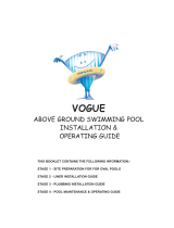
Waterco Commercial Multiport Valves
Features
• One-piece body made from moulded
glass-reinforced engineering plastic
provides incredible strength and
durability.
• 304 – Grade Stainless Steel used
throughout to withstand harsh water
conditions.
• Multiple valve positions available with
the turn of a handle, including: Filter,
rinse, bypass, backwash, winterise,
waste
• Supplied with pressure gauge and tted
with ¼ inch BSP air release valve.
• Sight glass tted to waste line for easy
inspection of the backwash water.
• Designed for a 400 kPa (58 psi) operating pressure.
Connecting Multi-Port Valve to Filter System
Use care before assembly not to damage union sealing surfaces or O-Ring. Install union O-Rings in
groove; tighten union collar hand tight.
FOR SLIP FITTINGS: Use correct solvent/cement when tting piping or adapters to slide valve. The
valve body is ABS plastic, thus any good quality ABS to PVC solvent can be used. Use primer on PVC
components only. Allow a minimum of four hours drying time prior to pressure testing or operation.
To avoid serious personal injury or property damage, follow cement manufacturer’s instructions
exactly.
Multiport Valves and Waterco Filter Models
Part Number Valve Model Filter Models Connections
2280600 TM 65 mm MPV S1050
S1200 65 mm
22905010 SM 65 mm MPV
SM1200
SMD1050
SMDD 900 -1050
65 mm
228800 TM 80 mm MPV S1200 80 mm
2290820 SM 80 mm MPV
SM1200 - 1400
SMD 1050 -1400
SMMD 900 -1400
SPPD 1050 -1200
80 mm
2291005 SM 100 mm MPV
SMD 1200 -1800
SMDD 1200 -1800
SPDD 1400 -1600
100 mm
• TM = Top Mount • SM = Side Mount
I pg 02
INLET
FILTER
WASTE
FILTER
OUTLET
RETURN

FUNCTIONS OF THE MULTI-PORT VALVE
Hazardous pressure. Can cause severe injury or
major property damage from valve blow up.
Release all pressure and read instructions before working
on system.
To avoid severe injury and major property damage,
stop pump before changing handle positions.
To avoid major property damage due to flooding,
make sure pointer is accurately positioned and down
all the way before restarting pump.
Hazardous
Hazardous
pressure
WARNING
!
!
Press down on handle to release pressure before turning.
1. FILTER – Normal position during operation of system.
2. BACKWASH – Position when operating system to purge lter of accumulated debris. This
normally is necessary when lter pressure gauge reads 10 PSI higher than starting pressure
on a clean lter. Consult your lter operating instructions.
3. RINSE – This position is only used with sand lters and is designed to ush stray sand from
system before returning to lter operation after backwashing. Consult your lter operating
instructions.
4. WINTERISE – Allows drain and winterise lter and pump according to manufacturer’s
instructions.
5. BY-PASS – This position permits pump to continue recirculating water (chemicals, heat,
etc.) without ow through lter. This is advantageous when lter or its components are being
repaired or replaced.
6. WASTE – This position permits draining or lowering of pool water level. When pump is
stopped with valve in this position, quickly move handle to another position to avoid air
getting into piping.
VALVE MAINTENANCE
To avoid severe personal injury and major property
damage, stop pump and release all pressure from
system before servicing valve.
!
No regular maintenance is required for proper operation of multi-port valve.
Winterizing For Freezing Climates:
Place valve handle in winterise position.

Waterco Commercial Multiport Valves
PART REPLACEMENT
To prevent ooding, make sure that system is drained or isolation valves are closed before opening
multi-port valve.
Replacing Handle:
1. Place handle in “FILTER” position.
2. Remove handle pin from handle; remove handle
and replace with new one, making sure pointer
is in “FILTER” position.
3. Replace pin by tapping lightly into place with
hammer.
Replacing Cover and Rotor Assembly
(as a unit):
1. STOP PUMP and release all pressure from
system.
2. Remove all bolts and nuts around perimeter of
cover.
3. Remove assembly by lifting straight up.
4. Align cover pin (see Figure 2) and install new
cover and plug. Press down on cover to allow
bolts to engage nuts; tighten each bolt securely.
Replacing Internal Valve Parts:
1. STOP PUMP and release all pressure from system.
2. Place handle in “FILTER” position.
3. Remove all the bolts and nuts in order to replace any internal parts.
4. Remove cover by lifting straight up.
5. Remove handle pin and handle (See procedure “Replacing Handle” above)
6. Remove washer.
7. While disassembled, check condition of plug, rubber gasket, spring, O-Ring, and internal plastic
washer. If any of these parts appear worn, replace them.
8. Reassemble plug, cover, and handle by compressing spring (See Figures 1 and 2) and reversing
procedure “Replacing Cover and Rotor Assembly” above.
9. Before reinstalling cover, be sure plug and handle are in same position as when cover was
removed.
10. Tighten each bolt securely.
Figure 1
Figure 2
Align Tabs
Handle
Pin
Spring
I pg 04

Spider Gasket Replacement:
NOTICE: Read instructions completely before starting.
1. STOP PUMP and release all pressure from system.
2. Remove the bolts and nuts holding the cover to the valve body. Remove the cover assembly.
3. Remove the old gasket from the valve rotor.
4. Make sure that the gasket groove is free of water, grease, oils, debris and parts of the old gasket.
Use alcohol to degrease.
5. NOTICE: Once this step is started, continue through Step 9 without interruption. Apply glue
sparingly (a bead about 1/16” wide) to the bottom only (not the sides) of the spider groove in the
valve body. The glue lines must be continuous and intersect at the intersections of the grooves.
6. Insert the new gasket into the groove with the rounded bead up. Press the gasket rmly into all
groove areas to seat the new gasket evenly.
7. Align the tab on the cover assembly with the pin on the valve body (See Figure 2) and insert the
cover assembly into the body, fastening it with the bolts and nuts removed in Step 2. Tighten all
bolts securely.
8. Depress the valve handle and rotate it to the closest standard position (FILTER or RINSE), being
careful not to rub the plug on the new gasket. Release the handle, allowing the plug to hold the
gasket in place while curing.
9. Minimum cure time is 2 hours. Curing for 24 hours is recommended for full strength
Valve Position Functions
Valve Setting Flow direction through valve
FILTER PUMP — TOP — THROUGH FILTER — BOTTOM — RETURN
For normal filtration through filter.
BACKWASH PUMP — BOTTOM — THROUGH FILTER — TOP — WASTE
For reversing flow for cleaning filter.
RINSE PUMP — TOP — THROUGH FILTER — BOTTOM — WASTE
For initial start-up cleaning plus resetting filter bed after backwashing.
WASTE PUMP — WASTE
For draining water.
WINTERISE NO CIRCULATION PAST PUMP PORT
For shutting off all flow to filter.
BY PASS Air fittings.

Waterco Commercial Multiport Valves
Top Mount Configuration
Filter Mode Backwash Mode
Side Mount Configuration
Filter Mode Backwash Mode
Warranty is stated in a separate document
I pg 06
OUTLET
VALVE
MULTIPORT VALVE
SAND
DIRT
FLUSHED
OUT
MULTIPORT VALVE
TO WASTE
OUTLET
VALVE
INLET
VALVE
DIRT
FLUSHED
OUT
SAND
INLET
VALVE
TO
DRAIN

Multiport Valve 65 mm (Side Mount) Assembly
Item Qty Part Number Name
1 1 621451 HANDLE
2 1 621111 HANDLE PIN
3 12 W12109 SCREW
4 1 W02627 TEFLON WASHER
5 2 621201 AXIAL O’RING
6 1 W02628 TEFLON WASHER
7 1 621182 SPRING
8 1 621152 LID O’RING
9
1 621233 ROTOR WITH GASKET
1 621234 ROT0R
1 621235 SPIDER GASKET
10 2 620221 AIR RELIEF WITH O’RING
11 1 6211302 LIF
12 1 6213021 BODY
13 3 63406554 O’RING
14 3 644490 B/U PLAIN END
15 3 63406551BLK B/U LOCK NUT
16 1 621381 SIGHT GLASS
17 1 621341 SIGHT GLASS GASKET
18 3 112780 COUPLING 80 mm
19 12 W02624 NUT

Waterco Commercial Multiport Valves I pg 08

Multiport Valve 80 mm (Top Mount) Assembly
Item Qty Part Number Name
1 1 621100 HANDLE
2 1 6211020 HANDLE PIN
3 1 6211310 LID
4 1 621243 ROTOR
5 1 621272 SPIDER GASKET
6 1 6211060 TEFLON WASHER
7 1 621192 SPRING
8 2 621202 O’RING AXLE
9 1 621192 BODY (T/MOUNT)
10 1 621193 SLEVE
11 1 621142 O’RING LID
12 2 620221 AIR RELIEF VALVE
13 1 621341 SIGHT GLASS GASKET
14 1 621381 SIGHT GLASS
15
3 W02255BLK B/U P/END 80 mm
3 W02253BLK B/U LOCK NUT 80 mm
3 W02249 O’RING B/U 80 mm
16 14 W12109 BOLT M6x32
17 14 W02624 NUT M6
18 1 621013 DIFFUSER
19 1 621194 DIFFUSER O’RING
20 1 W02742 O’RING 9 mm

Waterco Commercial Multiport Valves I pg 10

Multiport Valve 80 mm (Side Mount) Assembly
Item Qty Part Number Name
1 1 621100 HANDLE
2 1 621193 SLEVE
3 1 6211020 HANDLE PIN
4 2 621202 O’RING AXLE
5 14 W12109 SCREW
6 14 W02624 NUT
7 1 6211310 LID
8 1 621142 O’RING LID
9 1 6211060 WASHER
10 1 621192 SPRING
11 1 621243 ROTOR
12 1 621272 SPRIDER GASKET
13 1 621293 BODY
14 5 W02253BLK LOCK NUT B/U 80
15 5 W02255BLK PLAIN END B/U 80
5 W02255EBLK PLAIN END B/U 90
16 5 W02249 O’RING B/U 80
17 5 620221 AIR RELIEF VALVE
18 1 621341 GASKET SIGHT GLASS
19 1 621381 SIGHT GLASS

Waterco Commercial Multiport Valves I pg 12

Multiport Valve 100 mm Assembly
Item Qty Part Number Name
1 1 621100 HANDLE
2 1 6211020 HANDLE PIN
3
24 W12781 SCREW
24 W12783 WASHER SPRING
48 W12782 WASHER FLAT
4 1 6211060 WASHER
5 1 621202 AXIAL O’RING
6 1 621193 SLEVE
7 1 62110150 SPRNG
8 1 62110110 LID O’RING
91 62110220 ROTOR
1 62110130 SPIDER GASKET
10 2 620221 AIR RELIEF VALVE
11 1 6211028 LID
12 1 6211029 BODY
13 5 W02553 O’RING
14 5 12221011 B/U PLAIN END
15 5 1221009 B/U LOCK NUT
16 1 621381 SIGHT GLASS
17 1 621341 SIGHT GLASS GASKET
18 24 W02624 NUT

Waterco Commercial Multiport Valves I pg 14

Waterco Limited ABN 62 002 070 733
(ZZM1438) 05/2012
Offices - AustrAliA
NSW - SYDNEY
(HEAD OFFICE)
Tel: +61 2 9898 8600
QLD - BRISBANE
Tel: +61 7 3299 9900
VIC/TAS - MELBOURNE
Tel: +61 3 9764 1211
WA - PERTH
Tel: +61 8 9273 1900
SA/NT - ADELAIDE
Tel: +61 8 8244 6000
ACT DISTRIBUTION
Tel: +61 2 6280 6476
Offices - OVerseAs
WATERCO (EUROPE) LIMITED
Sittingbourne, Kent, UK
Tel: +44 (0) 1795 521 733
WATERCO FRANCE
Saint Priest, France
Tel: +33 4 72 79 33 30
WATERCO (USA) INC
Augusta, Georgia, USA
Tel: +1 706 793 7291
WATERCO CANADA
Longueuil, Quebec, Canada
Tel: +1 450 748 1421
WATERCO (NZ) LIMITED
Auckland, New Zealand
Tel: +64 9 525 7570
WATERCO © LIMITED
Guangzhou, China
Tel: +86 20 3222 2180
WATERCO (FAR EAST) SDN BHD
Selangor, Malaysia
Tel: +60 3 6145 6000
PT WATERCO INDONESIA
Jakarta, Indonesia
Tel: +62 21 4585 1481
WATERCO SINGAPORE INTL PTE LTD
Nehsons Building, Singapore
Tel: +65 6344 2378
/