AGS CH4CO-50 Mini Merlin Dual Gas Detector User manual
- Category
- Carbon monoxide (CO) detectors
- Type
- User manual

Mini Merlin Installation, Operation & Maintenance
Rev: 05 09-22 1
Mini Merlin CH4CO-50
Dual Gas Detector
Installation, Operation & Maintenance Manual
Please read this manual carefully and retain for future use.
For specific requirements that may deviate from the information in this guide – contact your supplier.
American Gas Safety LLC
www.americangassafety.com

Mini Merlin Installation, Operation & Maintenance
Rev: 05 09-22 2
Contents
Safety Information .................................................................................... 3
Carbon Monoxide – General Information .................................................................. 4
Methane – General Information ................................................................................. 4
Installation ................................................................................................. 5
Typical Application & Location .................................................................................. 5
Mounting & Cabling ................................................................................................... 6
Circuit Board Overview ............................................................................................. 7
Wiring – Gas Solenoid Valve ..................................................................................... 7
Wiring – Appliance Limit Circuits .............................................................................. 8
Wiring – Adaptable Outputs ...................................................................................... 8
Wiring – Pilot Water Heater & Boiler Limit Breaker ................................................... 9
Wiring – Remote Shut Off.......................................................................................... 9
Auto Reset & Buzzer Switches .................................................................................. 9
Building Management System ................................................................................ 10
Operation ................................................................................................ 10
Initial Power Up ....................................................................................................... 10
Digital Indications .................................................................................................... 10
Alarm Set Points ...................................................................................................... 10
Alarm Reset ............................................................................................................. 11
Remote Shut Off Indication ..................................................................................... 11
Manual Circuit Simulation Test ............................................................................... 11
End of Operational Life (EOL) ................................................................................. 11
Maintenance ............................................................................................ 12
Cleaning .................................................................................................................. 12
Manual Circuit Simulation Test ............................................................................... 12
Bump Test (Gas Response Check) ......................................................................... 12
Bump Test Procedure ............................................................................................. 13
Test Record ............................................................................................. 14
Specification ........................................................................................... 15

Mini Merlin Installation, Operation & Maintenance
Rev: 05 09-22 3
Safety Information
Before any installation, use or maintenance read this manual carefully.
The information contained within this manual should be referenced for typical installation and operation only.
For site specific requirements that may deviate from the information in this guide – contact your supplier.
If this product is used in a manner not specified by the manufacturer, the safety provided by the product may be impaired.
This product is designed for indoor operation only.
Detectors and cables must be protected against mechanical damage.
The internal fuse should be replaced only with the same type. Anti-surge fuse 3.15A 250Vac 5x20.
The expected lifetime of gas sensor elements is 5 years upon initial power up. The device will display a message to indicate
this time and should immediately be replaced.
It is recommended that this product be commissioned upon installation and serviced annually.
Do not apply lighter gas or other aerosols to the product – this will cause extreme damage.
High concentrations of alcohol / ethanol found in many products may damage, deteriorate, or affect the gas sensing
elements – Avoid exposure near your device.
This equipment is designed to detect carbon monoxide and natural gas only - from any source of combustion.
This product is not designed to detect smoke, fire or other gases and should NOT be used as such.
This device provides early warning of the presence of methane or carbon monoxide, usually before a healthy adult would
experience symptoms. This early warning is possible provided your alarm is located, installed and maintained as described
in this guide.
This device requires a continual supply of electrical power – it will not work without power.
This device should not be used to substitute proper installation, use and / or maintenance of fuel burning appliances
including appropriate ventilation and exhaust systems.
This device does not prevent methane or carbon monoxide from occurring or accumulating.
Actuation of your alarm indicates the presence of dangerous levels of Methane or CO.
The device can respond to other gases other than its intended target such as Hydrogen (H2), Ethylene (C2H4) and Nitric
Oxide (NO). In addition, the Methane sensor may react to iso-butane.
Seek fresh air supply and contact your local gas emergency service should you suspect a gas leak.
This device may not fully safeguard individuals with specific medical conditions.
If in doubt, consult a doctor / physician.
Your product should reach you in perfect condition, if you suspect it is damaged, contact your supplier.
Warranty Statement
Warranty Coverage: The manufacturer warrants to the original consumer purchaser, that this product will be free of defects in
material and workmanship for a period of two (2) years from date of purchase.
The manufacturer’s liability hereunder is limited to replacement of the product with repaired product at the discretion of the
manufacture. This warranty is void if the product has been damaged by accident, unreasonable use, neglect, tampering or other
causes not arising from defects in material or workmanship. This warranty extends to the original consumer purchaser of the product
only. Disclaimers: Any implied warranties arising out of this sale, including but not limited to the implied warranties of description,
merchantability and intended operational purpose, are limited in duration to the above warranty period. In no event shall the
manufacturer be liable for loss of use of this product or for any indirect, special, incidental or consequential damages, or costs, or
expenses incurred by the consumer or any other user of this product, whether due to a breach of contract, negligence, strict liability
in tort or otherwise. The manufacturer shall have no liability for any personal injury, property damage or any special, incidental,
contingent or consequential damage of any kind resulting from gas leakage, fire or explosion. This warranty does not affect your
statutory rights. Performance: During the above warranty period, your product will be replaced with a comparable product if the
defective product is returned together with proof of purchase date. The replacement product will be in warranty for the remainder of
the original warranty period or for six months – whichever is the greatest.
Information on waste disposal for consumers of electrical & electronic equipment.
When this product reaches the end of its life it must be treated as Waste Electrical & Electronics Equipment (WEEE).
WEEE marked products must not be mixed with general household waste, but kept separate for the treatment, recovery and
recycling of the materials used. Please contact your supplier or local authority for details of recycling schemes in your area.
At the end of their working life, electrochemical sensors should be disposed of in an environmentally safe manner. Alternatively, they
can be securely packaged and returned to AGS clearly marked for disposal. Electrochemical sensors should not be incinerated as
this may cause the cell to emit toxic fumes.

Mini Merlin Installation, Operation & Maintenance
Rev: 05 09-22 4
Carbon Monoxide – General Information
Carbon monoxide (CO) is a poisonous, colourless, odourless, and tasteless gas. Although it has no detectable odor,
CO is often mixed with other gases that do have an odor. So, you can inhale carbon monoxide right along with gases
that you can smell and not be aware that CO is present.
SYMPTOMS OF CARBON MONOXIDE GAS POISONING
The following symptoms are related to CO poisoning and should be discussed with all members of the household,
facility or person(s) frequenting monitored areas.
• Mild Exposure: Slight headache, nausea, vomiting, fatigue, flu-like symptoms.
• Medium Exposure: Severe headache, drowsiness, confusion, increased heart rate.
• Extreme Exposure: Unconsciousness, convulsions, cardio-respiratory failure, death.
CARBON MONOXIDE GAS LEVELS
This product is equipped with a digital display that shows levels of CO displayed in PPM (parts per million).
See the specification table for how this product monitors Carbon Monoxide gas.
POSSIBLE SOURCES OF CARBON MONOXIDE GAS
Inside your home or facility, gas appliances used for heating, water heating and cooking are the most likely sources of
CO. Vehicles running in attached garages can also produce dangerous levels of CO.
CO can be produced when burning any fossil fuel, such as gasoline, propane, natural gas, oil and wood. It can be
produced in any fuel burning appliance that is malfunctioning, improperly installed or insufficiently ventilated.
• Automobiles, gas stoves, water heaters, portable fuel burning heaters, fireplaces.
• Blocked chimneys or flues corroded or disconnected vent pipes.
• Burning charcoal or fuel in grills in an enclosed area or near the home.
Methane – General Information
Methane is non-toxic and it can be harnessed as an energy source. However, methane is highly explosive and it can
cause death by asphyxiation. Methane on its own isn't poisonous, it has the potential to become poisonous when
mixed with other substances. That potential exists when natural gas (CH4), which is 97% methane, is burned in
houses, offices and businesses. The burning of natural gas without proper ventilation can produce carbon monoxide,
a deadly gas that is difficult to detect.
SYMPTOMS OF METHANE GAS EXPOSURE
Methane gas is relatively non-toxic and associated with being a simple asphyxiator displacing oxygen in the lungs.
However, Methane is extremely combustible. Exposure to high levels of Methane can cause: Suffocation; Loss of
consciousness; Headache and dizziness; Nausea and vomiting; Weakness; Loss of co-ordination and increased
breathing rate.
METHANE GAS LEVELS - LEL%
The LEL (Lower Explosive Limit) of methane is 5% BV (by volume of air).
So, we call 5% BV (by volume) the same as 100% of the LEL (Lower Explosion Limit). This product is equipped with a
digital display that shows the level of natural gas in the area referred to as LEL% (a percentage of the LEL) and will
alarm based on the following principle of gas detection.
In simplified terms, a level of 8% LEL or less on this device is generally considered safe and acceptable.
For more information, please visit our website or contact your local AGS distributor.

Mini Merlin Installation, Operation & Maintenance
Rev: 05 09-22 5
Installation
Typical Application & Location
Installation must be in accordance with recognised standards in the country concerned, for North America, NEC / CEC
regulations should be followed!
Access to the interior of the device, when carrying out any work, must only be conducted by trained personnel!
Before carrying out any work ensure local regulations and site procedures are followed!
Easy access is recommended for both status observation and alarm purposes and must be located out of reach of the public!
Isolate the equipment from all hazardous live power sources before opening the cover!
Avoid conditions of any other environmental factors outside of the specification that could potentially impede the accuracy
and operation of the detector such as condensation; vibration; temperature, pressure, the presence of other gases,
electromagnetic interference, and draft zones!
Your new Mini Merlin is a dual gas detector carefully designed to monitor levels of Methane (CH4) and Carbon
Monoxide (CO) in the air. If there is a dangerous build-up of target gas at the sensor, this device can shut off the gas
supply via a gas safety valve and /or gas fired appliance(s). This device has additional features for resetting systems,
as well as audible and visual alarms and can also be integrated with a Building Management System (BMS).
Your detector should be installed in areas at risk of gas leaks e.g., over boilers, valves, or meters. Located in positions
determined by those who have knowledge of gas dispersion, the process plant system and equipment involved, and
in consultation with both safety and electrical engineering personnel.
Take in to account the design of the air flow patterns within the zone area. Detectors should be installed in the correct
orientation, as recommended by the manufacturer, and ease of access should be accounted for to allow for any bump
tests and other forms of maintenance throughout its operating life.
There are no official figures of the area coverage of a gas detector; however, 50-100m2 per detector is a reasonable
general guide therefore consider multiple detectors may be required to adequately protect property and persons.
The target gas will only be identified when contact is made with the sensing element itself.
Recommended heights may vary based on air flow and temperature conditions in addition to the proposed application
and location. The device should be mounted near the boiler or gas fired appliances such as domestic & commercial
boiler rooms and basements.
As a guide only we recommend the following:
• 6ft from sources of combustion e.g., boiler s/ heaters / gas fired appliances etc.
• 4ft from draft zones and ventilation areas e.g., windows, doorways, and a/c units etc.
• 5ft from ground level.
There are no specific standards governing gas detector location (unlike fire detection systems); there are, however,
general guidance documents. The most relevant being IEC 600-79-29-2: Explosive Atmospheres – Part 29: Gas
detectors – Selection, installation, use and maintenance of detectors for flammable gases and oxygen. Much of what it
covers is also relevant to toxic gas detection.

Mini Merlin Installation, Operation & Maintenance
Rev: 05 09-22 6
Mounting & Cabling
If mounting direct to wall - ensure the wall surface is flat to prevent base distortion!
Ensure the rear base is installed in the correct orientation as shown!
Where cable glands/conduits are used for wire entry, use 20mm (3/4 inch) max separated by at least 20mm!
Any parts that form part of the connections/installation must have a minimum fire retardant rating of UL94V-1!
Damage to PCBs when creating cable entry points or attempting to remove the circuit board may void any warranty!
The monitor is designed for either surface mounting or mounted on a one or two gang electrical box.
Restrain the hazardous live wiring from accidental loosening to prevent wires from moving after installation and touching
parts of opposite polarity or at low voltages!
Isolate the equipment from all hazardous live power sources before opening the cover!
When metal conduit is used provision shall be provided by the installer for bonding in accordance with the NFPA70!
Installation must be in accordance with recognised standards in the country concerned, for North America, NEC / CEC
regulations should be followed!
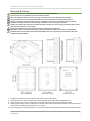
1. Carefully remove the front cover from the unit by using an M3 socket wrench.
2. Using the rear base - mark mounting holes to the wall or align with an appropriate gang/pattress box.
3. Fixing straight to wall – drill 0.2” (5mm) hole, insert plugs and use the four screws (No.4 Pozi) provided.
4. There are pre-fractured areas for cable entry on the rear of the base and pilot holes positioned on the top and bottom
of the enclosure suitable for entry points up to ¾” (20mm).
5. After executing the mounting/connections – secure the front cover with all M4 bolts and insert security caps provided.

Mini Merlin Installation, Operation & Maintenance
Rev: 05 09-22 7
Circuit Board Overview
Damage to PCBs when creating cable entry points may void any warranty!
Take care when making connections to high voltage connectors!
Any damage attempting to remove the circuit board may void any warranty!
All Class 2 wiring is to be installed within flexible tubing to maintain segregation between circuits!
Wiring of different circuits shall be separated by means of routing, clamping or barrier!
For field connections other than connected Heat detectors use wires suitable for at least 167°F (75°C)
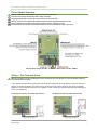
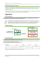
Wiring – Gas Solenoid Valve
When the installation includes a standing pilot, ensure the internal auto reset dip switch is in the OFF position requiring a
manual reset of the fuel supply!
A gas solenoid valve should be powered using the terminals marked [VALVE OUT]. When the valve out terminal is
wired to a normally closed (NC) gas solenoid valve, the device can be used to isolate the gas supply for multiple
appliances. Use an external transformer (not supplied) to close a 24VAC gas solenoid valve that could supply gas to
one or more appliances.
Gas Supply Controlled by 100-120VAC Solenoid Valve Gas Supply Controlled by 24VAC Solenoid Valve

Mini Merlin Installation, Operation & Maintenance
Rev: 05 09-22 8
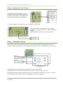
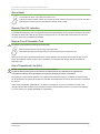
Wiring – Appliance Limit Circuits
The device can be used to directly shut down a
gas appliance when a fault condition is detected
(gas leak) by wiring terminals of one BMS into the
low voltage safety limit circuit of the appliance.
To connect both BMS to the safety limit circuit of an appliance - wire in series.
If dangerous levels of gas are detected or the mini merlin
encounters a power failure, the circuit is opened, disabling the
appliance.
Multiple appliance limit switches can be wired in series.
Wiring – Adaptable Outputs
The mini merlin can be used to effect external relays and contactors to disable multiple appliances when a fault
condition is detected. Multi-pole relays can interrupt power to electrical circuits controlling boiler, valves and pumps.
Low voltage wiring is to be inserted into the external limit circuit of a gas appliance.
The diagram shows a 120VAC general purpose primary coil with two sets of switches, each with
Normally Open (NO) and Normally Closed (NC) contacts. These contacts are rated for up to 12A AFL. They can be
used to break a low or line volt limit circuit or completely remove power to an appliance.

Mini Merlin Installation, Operation & Maintenance
Rev: 05 09-22 9
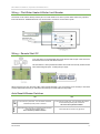
Wiring – Pilot Water Heater & Boiler Limit Breaker
The device can be used to directly shut the pilot of a water heater in an alarm or power failure state using a product
from Field Controls. The BMS terminals may also be used to connect to a home alarm system.
Wiring – Remote Shut Off
Your mini-merlin can be integrated with remote devices with an open /close circuit via
the Remote Shut-Off volt free switch terminal.
This terminal has a factory fitted link installed. This terminal is normally closed and will
alarm when energised open - isolating the gas supply.
When using this input, only the mains utility output shall de-energize. If you are using the CO or NG relay to shut down
a boilers external limit circuit, you will need to wire the input in series with the relay output.
Auto Reset & Buzzer Switches
ON
OFF
Auto
Reset
In the event of a power loss – the mini-merlin will restart
automatically when power is restored.
In the event of a power loss – the mini-merlin will need to
be reset manually when power is restored.
This is the factory default condition.
Buzzer
The buzzer will sound every 15 seconds during pre-alarm
and continuously at alarm level.
This is the factory default condition.
The buzzer will not sound at any gas level.

Mini Merlin Installation, Operation & Maintenance
Rev: 05 09-22 10
Building Management System
This device can be integrated with a Building Management System (BMS), a home alarm system, or be used as part
of a boiler low voltage safety limit to make or break a circuit on both gases separately, (valve open or valve closed)
depending on the system.
These switches can be used for a variety of purposes including triggering alarm contacts, operating and external relay
for multiple appliance shutdown and generating status signals for a BMS system.
Operation
Initial Power Up
When power is removed manually or due to an unpredicted power failure the CO and NG BMS circuit will change state
switching off boilers/appliances via a limit switch if configured to do so!
When electrical power is supplied, press, and hold the touch sensor on the front cover for ~3 seconds.
The detector enters a stabilisation phase for approximately one minute – during this period the device is not
operational. If the detector has been configured to ‘Auto-Reset’ – your device will power up automatically
when electrical power is supplied. To turn your device off, remove/isolate electrical power supply.
Digital Indications
Alarm Set Points
When the detector reaches alarm levels the maximum concentration detected will be saved and the screen value will switch
between the maximum (MAX) and the real time current value!
When the device has reached an alarm state, the concentration indicator will remain red even if gas levels are safe until the
device is reset by pressing the touch sensor once!
An audible buzzer will sound if the internal buzzer switch is on!
Target Gas
Pre-Alarm
Buzzer
Alarm
Buzzer
Carbon Monoxide (CO)
▲ 25ppm
Beep every 15s
▲ 50ppm
Continuous Sound
Methane/Natural Gas (NG)
▲ 8% LEL
▲ 10% LEL
▲Rising Alarm PPM (Parts Per Million) LEL% (Lower Explosive Limit)

Mini Merlin Installation, Operation & Maintenance
Rev: 05 09-22 11
Alarm Reset
To reset after an alarm - press the touch sensor once.
If the device enters an alarm state at any time, the gas level indicator will remain red to alert the user that a
high/dangerous level of gas has been detected, until the device is reset.
Remote Shut Off Indication
A message will display if the device is integrated with remote shut off devices such as smoke or fire alarms etc. When
activated, the device will isolate the gas supply if configured to do so. The mini merlin would need to be reset once
any issues have been investigated and rectified.
Manual Circuit Simulation Test
The manual circuit test does not check the gas sensor itself!
Press and hold the touch sensor during normal operation.
This option gives the user the opportunity to test each relay/output in response to gas.
When the touch button is pressed and held during normal operation the mini merlin will simulate an open circuit to
ensure all configured systems, outputs, alarms, indications, and other external devices operate as intended in
response to gas.
End of Operational Life (EOL)
The EOL is approximate from the first five (5) hours of continuous power!
The EOL will depend on the type of gas your detector is targeting and may vary depending on its application and
environmental conditions such as the frequency of exposure to the target gas, poisons, or inhibitors!
The typical life of a gas detector depends on its application and intended target gas, in addition the operational life
can be prolonged if the system and equipment is installed and maintained in accordance the instructions stated within
this manual.
At the end of its predicted operational life – the detector will display an ‘End of Life’ indication on screen. This
message indicates that the detector has reached its expected operational lifecycle and no gas levels are displayed.
You must contact your supplier immediately for replacement.

Mini Merlin Installation, Operation & Maintenance
Rev: 05 09-22 12
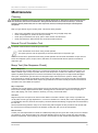
Maintenance
Cleaning
Concentrations of alcohol found in many products may damage, deteriorate, or affect the gas sensing elements such as
wine; deodorants; stain removers and thinners. Other gases and substances to avoid are corrosives (i.e., chlorine &
hydrogen chloride); alkali metals; basic or acidic compounds; silicones; tetraethyl lead; halogens and halogenated
compounds!
Keep your gas detector in good working order - follow these basic principles.
• Remove any dust/debris from the outer enclosure regularly using a slightly damp cloth.
• Never use detergents or solvents to clean your device.
• Never spray air fresheners, hair spray, paint or other aerosols near the device.
• Never paint the device. Paint will seal vents and interfere with the device.
Manual Circuit Simulation Test
The manual circuit test does not check the gas sensor itself!
Press and hold the touch sensor during normal operation.
This option gives the user the opportunity to test each relay/output in response to gas.
When the touch button is pressed and held during normal operation the mini merlin will simulate an open circuit to
ensure all configured systems, outputs, alarms, indications, and other external devices operate as intended in
response to gas.
Bump Test (Gas Response Check)
What is a Bump Test?
Gas response checks are often referred to as a ‘bump test’. Bump tests are important to make sure a device can
detect a release of gas as early as possible. The aim of the bump test is to make sure a detector is working at its
optimum by briefly exposing the unit to a known concentration of the target gas that usually exceeds the highest
alarm point. If the detector goes into alarm and all signals/outputs activate, then the system is working safely.
If the system fails to operate as intended in an alarm state, the gas detector must not be used until a full inspection
and service has been conducted. NFPA requires all gas detectors to be tested annually and that the test results be
recorded on site and available to inspectors.
Why is it important?
A detector may visually appear in good working order, but its sensitivity and accuracy can be inhibited by external
factors. Dust, humidity, temperature fluctuations, cleaning products, contaminants, exposure to its target gas or
sensor drift (ageing) can cause a decline in sensitivity, accuracy, and eventual failure.
How often?
Regular bump tests are important to make sure the detector can detect a release of gas as early as possible and
usually takes seconds (gas type dependant i.e., CO sensors will take over a minute) and is often completed alongside
a scheduled fire alarm test, however the frequency should be determined following an appropriate risk assessment by
the end user.
We recommend testing detectors every 12-18 months along with the regular fire test procedures and coincide with
the annual service message prompted on the detection system after each year of service/operation.
What do I need?
Contact your AGS representative for details of suitable bump testing kits and gases. Kits usually consist of a certified
gas cylinder or spray. We recommend only using AGS calibration gas kits to ensure correct flow rates meet AGS
technical requirements. A bump testing gas is usually a concentration mix that exceeds the highest alarm set point.

Mini Merlin Installation, Operation & Maintenance
Rev: 05 09-22 13
Bump Test Procedure
To increase reaction time, cover the escape vents at the sides of the device.
Always remove the regulator/valve if using a cylinder after use!
Always give at least five (5) minutes between testing the same unit or until gas has fully dispersed!
Always consider safety and use equipment in accordance with Safety Data Sheets!
Reference should always be given to any applicable national & local law and industry codes.
Generally, the gas concentration should be greater than the alarm threshold of the device.
Always remove the regulator/valve after use if using a cylinder!
All cylinders will re-seal upon removal of the regulator/valve!
Deviating from this test process is deemed improper and may affect the functional safety of your device!
Exposure to chemicals, smoke, or any other materials other than the gases intended to be monitored can seriously damage
the gas sensing elements!
Always allow a minimum of 5 minutes before testing the same unit!
1. Ensure you have the correct gas for the device type prior to application.
2. Offer up the applicator hose/cone or spray and apply to the small vents of the device located underneath.
3. Apply gas.
4. The device will enter alarm status after reaching alarm set point.
5. The device will activate all configured outputs/relays.
At this point…
6. Remove applicator hose/ cone or spray.
7. Reset by pressing the touch sensor.
8. Test complete.
9. Record your test details.

Mini Merlin Installation, Operation & Maintenance
Rev: 05 09-22 14
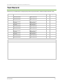
Test Record
Detectors are pre-calibrated prior to shipping with gas mixtures prepared to N.P.L standards (analytical tolerance: ±5%)
Date
Gas Details
Pass
Sign
CO ppm:
Batch/Cylinder No:
CH4/NG % LEL:
Batch/Cylinder No:
CO ppm:
Batch/Cylinder No:
CH4/NG % LEL:
Batch/Cylinder No:
CO ppm:
Batch/Cylinder No:
CH4/NG % LEL:
Batch/Cylinder No:
CO ppm:
Batch/Cylinder No:
CH4/NG % LEL:
Batch/Cylinder No:
CO ppm:
Batch/Cylinder No:
CH4/NG % LEL:
Batch/Cylinder No:
CO ppm:
Batch/Cylinder No:
CH4/NG % LEL:
Batch/Cylinder No:
CO ppm:
Batch/Cylinder No:
CH4/NG % LEL:
Batch/Cylinder No:
CO ppm:
Batch/Cylinder No:
CH4/NG % LEL:
Batch/Cylinder No:
CO ppm:
Batch/Cylinder No:
CH4/NG % LEL:
Batch/Cylinder No:
CO ppm:
Batch/Cylinder No:
CH4/NG % LEL:
Batch/Cylinder No:
Notes

Mini Merlin Installation, Operation & Maintenance
Rev: 05 09-22 15
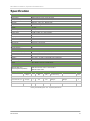
Specification
General
Model:
Mini Merlin CH4CO-50
Target Gases:
Methane/Natural Gas & Carbon Monoxide
Size: (H x W x D)
5.95 x 4.37 x 1.97” (151 x 111 x 50mm)
Housing Material:
ABS PA765 (Flame Rating UL94 V-1)
Mounting:
Safe Zone - Indoor use - Wall Mounted
Weight:
12.24oz (0.347kg)
User Interface
Display:
1.8” TFT
Screen Brightness:
Non-Adjustable
Visual Indicators:
TFT visual. Green: Normal; Yellow: Pre-Alarm; Red: Alarm
Audible Alarm:
>70dB @ 3.28ft (1m). Quiet conditions.
Buttons:
Multi-Function – Initial Start / Reset / Circuit Test
Language:
English
Power Supply
Power Consumption:
3W max
AC Power:
100-120V~ 50/60Hz
Internal Fuse:
Anti-Surge 3.15A 250Vac
Equipment
Overvoltage Category:
II
Pollution Degree:
2
Relays
Volt Free BMS relay output:
0.5A switching current (resistive load)
Environmental
Ingress Protection:
Not Formally Evaluated
Operating:
-10 ~ 50°C / 14 ~ 122°F 30 ~ 80% RH (non-condensing)
Storage:
-25 ~ 50°C / -13~122F° up to 95% RH (non-condensing)
Altitude Rating:
2000m
Wiring
Typical
Min. 18AWG / 75°C min / Tinned copper.
Approvals
Electrical Safety and
Electromagnetic Compatibility
UL61010-1/2012/R:2019-07.
CAN CSA C22.2 No. 61010-1-12/A1:2018-11
EMC EN 61326-1:2013
Sensor Specification
Gas Sensor
Indicating
Range
Steps
Response
(t90)
Recovery
(t10)
Alarm: 1
(Pre alarm warning)
Alarm: 2
*EOL
(Years)
Electrochemical Sensors
Carbon Monoxide (CO)
0-999ppm
1
<60s
<60s
▲25ppm
▲50ppm
5
Semiconductor Sensors
Methane (CH4)
0-20% LEL
0.1
<30s
<30s
▲8% LEL
▲10% LEL
10
▲ Rising Alarm ▼Falling alarm *EOL – Expected Operational Life

Mini Merlin Installation, Operation & Maintenance
Rev: 05 09-22 16
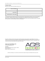
Installation Details
Please pass this manual to the system owner / user.
Date of Installation:
Installation Location:
Organisation:
Stamp/Signature of the installer:
We recommend all AGS gas detection equipment be commissioned by competent/trained engineers to ensure correct installation
and operation. The Merlin range of gas detectors are calibrated when manufactured, however, we strongly recommend the
detectors response and alarm signals are tested and validated once installed. This will ensure the equipment performs as intended
and is free from any unforeseen damage caused by transit/installation.
Every effort is made to ensure the accuracy of this document; however, AGS can assume no responsibility for any errors or
omissions in this document or their consequences. AGS would greatly appreciate being informed of any errors or omissions that
may be found in the content of this document. For information not covered in this document, or if there is a requirement to send
comments/corrections, please contact AGS using the contact details.
American Gas Safety LLC
www.americangassafety.com
Head office:
6304 Benjamin Road, Suite 502, Tampa, FL 33634
Tel: (727) 608-4375
Email: info@americangassafety.com
American Gas Safety LLC is the owner of this document and reserves all rights of modification without prior notice.
-
 1
1
-
 2
2
-
 3
3
-
 4
4
-
 5
5
-
 6
6
-
 7
7
-
 8
8
-
 9
9
-
 10
10
-
 11
11
-
 12
12
-
 13
13
-
 14
14
-
 15
15
-
 16
16


AGS CH4CO-50 Mini Merlin Dual Gas Detector User manual
- Category
- Carbon monoxide (CO) detectors
- Type
- User manual
Ask a question and I''ll find the answer in the document
Finding information in a document is now easier with AI
Related papers
-
AGS Mini Merlin CH4CO Owner's manual
-
-
-
-
-
-
-
AGS Carbon Monoxide and Nitrogen Dioxide Parksafe Detector User manual
-
AGS Merlin 1000SW+ i Gas Electric and Water Isolation Controller User manual
-
AGS Merlin 1000S Gas Proving and Isolation Controller User manual
Other documents
-
 CPS Products LSCG Quick start guide
-
Merlin 1000Splus Gas and Electric Utility Isolation Controller User manual
-
Vemer RGCO User manual
-
 PHD Products PHD Carbon Monoxide Alarm 13-027 User manual
-
MOES ZigBee User guide
-
BW Technologies XXYY-QT User manual
-
-
Crowcon Xgard Bright User manual
-
BW Technologies BWC4-Y-U User manual
-
3M MACURCO GD-6 User manual

