Page is loading ...

Sunbeam
Original Service Manual, Radiant Control Toaster
Models T20, T20A, T20B
Compiled by
Dave's Repair Service
©2004 All Rights Reserved
www.DavesRepair.com
(Note:
Due to the poor condition
of
the original
copy
of
this vintage
document, it was necessary
to
digitally remaster parts
of
it. The original
format,
layout,
and graphics have been painstakingly and
faithfully
reproduced.)

Sunbeam
CORPORATION
Service
Bulletin
No.
90-11
Toaster
May
28,
1953
INSTRUCTIONS FOR SERVICING SUNBEAM RADIANT
CONTROL TOASTER MODELS T20, T20A, & T20B
GENERAL
The
New Sunbeam Radiant Control Toaster is
a
1275 watt electric appliance with its
elements in series and _is
to be used
on ALTERNATING CURRENT ONLY
.
It
differs from
previous models and other
toasters
on
the
market in toasting control principle, in
the
method used
in
raising
and lowering the bread,
and in the
design of the
elements.
The
Toaster is much
less sensitive to differences in freshness or
moisture
content
of
the
bread,
or
to
variations
in line voltage than
previous
Toasters, because the toasting
cycle depends entirely upon the amount of heat radiated from the bread being toasted.
When
toasting one
slice, place it into
the
slot marked
"
ONE
SLICE
".
When toasting two
slices, they should be of uniform freshness to get uniform results.
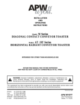
Attached at the end of this bulletin is a complete
descriptive
list of parts and parts
assemblies. These are
shown
in their relative positions on the detailed illustration on
the back of the parts list. The tools used for servicing the Toaster are shown at the end
of the bulletin.

2
WINDOW
END
ELEMENT
CENTER
ELEMENT
GUIDE
WIRE
CLOSED
END
ELEMENT
REFLECTOR
WINDOW
THERMOSTAT
ASSEMBLY
ADJUSTMENT
KNOB
ELEMENT
REFLECTOR
LIFT LEVER
BREAD LIFTER
ASSEMBLY
TRIP
LEVER
BREAD RACK

-
3
-
HOW THE TOASTER OPERATES
Put two slices of bread in the Toaster. The slice in the slot marked "One Slice" will
depress the Trip Lever, causing the Trigger Lever Assembly to close the contact points.
The elements will then heat up, and the expansion of the Center Element wire will allow
the Bread Lifter Assembly to go down slowly under its own weight.
When the bread is
toasted,
the heat radiated from the outer surface of the bread, in the
slot marked "One Slice", will cause the Thermostatic Blade to snap to "off" position,
causing the contact points
to
open. Then,
as
the elements cool, the wire in the Center
Element will contract, and force the Lift Lever Depression Bar down, causing movement of
the Lift Lever Assembly, which forces the Bread Lifter Assembly
to
slowly raise the
toasted
bread.
OPERATING PRINCIPLES
Uniformity of toasting, under varying conditions, such
as
bread size, moisture content of
bread, voltage, and Toaster temperature, is obtained in this Toaster
by
having the
Radiant Control Thermostat respond
to
only the surface temperature of the slice of bread
being
toasted.
As the bread surface begins
to toast,
it will rise in temperature, and
this temperature,
at
every instant, bears
a
close relationship
to
color
at
the same
instant. In this particular mechanism this surface temperature is measured
by
the heat
radiated (not conducted) from that surface
to
the Radiant Control Thermostat. The
Thermostat Assembly is unavoidably affected
by a
temperature rise
due to
the heating
up
of its surroundings,
but
it is
so
designed
as to
properly compensate for this effect
so
as to
have
a
net response
to
only the heat radiated from the bread surface. Consistent
operation
is assured
because
the Thermostat Blade operates with
a
snap action. Thus, it
is
absolutely free
of the effects of friction,
since,
in its snap motion, it
encounters
no resistance, frictional or otherwise, until
it
moves freely for
a
sufficient distance
to
have many times more force available
to do the work than is necessary.
Raising
or lowering of the
bread is obtained by making use of the energy
of expansion and
contraction
of the Center Element wire. Of course, this movement is very small and is
measured in thousandths of an inch,
but more
than
adequate
carriage movement is obtained
by a simple linkage which multiplies this movement approximately
175
times. Only the
movement
in the lower
range of temperature
(below
1000 F.) is used for
this
purpose since
it is undesirable to apply stress to
this wire while
at
or near
the operating temperature
of
approximately
1600 F.
The end elements are of unique design for the purpose of increasing the Toaster' s
efficiency. This design possesses much less heat capacity than an element of conventional
type, and consequently permits much faster toasting when the Toaster is cold.

-
4
-
RULES OF GOOD REPAIR PRACTICES
The success of the repair depends upon the repairman' s ability in following the rules of
good repair practices. These rules can
be
summed
up
as follows:
1. Read the Service Bulletin thoroughly.
2. Know what you are looking for. Never guess. Always investigate the source of
trouble. Ask, if you do not know.
3. Determine troubles
by
the process of elimination.
4. Every part, no matter how small, has
a job to
perform. Do not overlook the
smallest detail.
5.
Use
the proper tool. Keep tools in efficient working order.
6. Carefully handle smooth, plated, or Bakelite parts
to
prevent damaging or
scratching.
7. Make the repair like
you
would want it, if
you
were the customer.
A. DISASSEMBLY
1. Place Toaster onto Tool No.
1,
bottom side
up,
protecting the Shell from being
scratched. Pry off Adjusting Knob,
Key No. (26).
Remove Screws
(28)
and Washers
(27)
from Bottom Cover Assembly
(29)
along
with Screws
(30)
from center of Hinge Plate of
Bottom
Cover Assembly. Lift Base
(25)
off of mechanism assembly and remove
Hex
Nuts
(7)
with Washers
(8)
from Mounting
Plate
Assembly
(20).
Separate Plug and
Cord
Assembly
(24)
from Base.
Pry Cord Clip
(23)
from Mounting Plate Assembly
(20).
Remove
Screws
(2)
releasing End Shells
(5)
and Center Shell
(1),
then lift mechanism assembly
from Center Shell
(1)
.
2.
Set mechanism assembly on
end
so
that Thermostat Assembly
(12)
is facing
up.
If
Toaster is a model T20B,
remove
Carriage
Counter
Balance Spring (3A) . Four
turns of
the Spring
Hook over
the End Top Plate
(3)
and the loop end hooks through the
hole in
the Bread Lifter Assembly
(17)
Remove Screws
(13) with Washers
(8)
separating Switch
Lead (21) and Upper Lead Bracket from Thermostat Assembly
(12).
Raise Thermostat
Assembly until Reflector clears
window
in element, then slide it clear of mechanism.
Remove Nut (7) and
Washer
(8)
on Mounting Plate Assembly
(20)
disconnecting Switch
Lead
(2 1).
Release Guide Wires
(9)
from Mounting Plate Assembly. Set mechanism back
into upright position to remove Hex Nut (7) and Washer
(8)
from Center Element
Assembly. Use offset screwdriver to hold stud
when
loosening or tightening Hex Nut
(7).
Then remove Screws
(2)
lifting End Top Plate
(3)
with Guide Wires and Window End
Assembly
(11)
from mechanism, being careful so that the Guide Wires do not catch in
the Element Wires and Rack. The Upper Bus Bar is part

-
5
-
of the Element Assembly; the Insulator
(4)
slides off of the Bus Bar. Now the Window
End Assembly, End Top Plate, and Guide Wires can be separated. Follow the same
procedure and precautions in removing the other End Top Plate
(3)
and Closed End
Element Assembly
(6),
but first remove Hex Nut
(7)
and Washer
(8),
disconnecting Lower
Bus Bar from Center Element.
3. Release Guide Wires, then remove Screws
(2).
Lift Center Element Assembly
(10),
with
Center Top Plate attached, clear of the mechanism. Remove Screws
(18),
releasing
Lifter Lever Assembly
(19)
from mechanism, then remove Screws
(2)
freeing Frame Cross
Yoke
(15).
Remove Screws
(2),
and lift Side Frame
(14)
from Mounting Plate Assembly
and clear of Bread Lifter Assembly
(17).
Follow the same procedure for other Side
Frame. Now you can pick
up
Bread Lifter Assembly off of Mounting Plate Assembly.
Unhook Lift Lever Depression Bar
(22)
from Lift Lever Assembly, separating Lift Lever
Depression Bar from the Mounting Plate Assembly.
B. REASSEMBLY
1.
Set
Mounting Plate Assembly
(20)
on
top
of Lift Lever Depression Bar
(22)
and hook
Lift Lever Assembly
(19)
onto Lift Lever Depression Bar. Connect Switch Lead
(21)
with
Washer
(8)
and Hex Nut
(7)
onto Mounting Plate Assembly. Place Bread Lifter Assembly
(17)
on
top
of Mounting Plate Assembly.
Set
Side Frame Assemblies
(14)
and
(16)
into
place with the Bread Lifter Assembly
set
in the slots and fasten with Screws
(2).
Now
with the Bread Lifter Assembly
set
in slots of Side Frame Assemblies and Lift Lever
Assembly, fasten Frame Cross Yoke
(15)
with Screws
(2)
onto Side Frame Assembly.
2.
Set
Window End Element Assembly
(11)
and Closed End Element Assembly
(6)
into place.
Install Guide Wires
(9)
onto Center Top Plate of Center Element Assembly
(10). Set
Center Assembly into place with Upper and Lower Bus Bars of
the End
Element Assemblies
on respective terminals,
so
that Adjustment Screw is in center hole of Lift Lever
Depression Bar, and fasten Center Top Plate with Screws
(2).
Hook Guide Wires
onto
Mounting Plate Assembly.
Replace
Washer
(8)
and Nut
(7)
on Bus Bar terminals of Center
Element. Slide Insulators
(4)
onto Bus Bar of Window
End
Element. Slide Thermostat
Assembly
(12)
into place, and
connect
Upper Lead Bracket of Element Assembly and
Switch Lead Wire
(21)
onto Thermostat Assembly with Washers
(8)
and Screws
(13).
Hook
3 to
4 turns of
Carriage Counter Balance
Spring
(3A)
over Top End Plate
(3).
Hook the
looped end in
hole
in Bread Lifter Assembly (17). Fasten End
Shells
(5)
and
Center
Shell
(1)
onto
mechanism
assembly
with Screws
(2)
. Use Tool No. 2
when
fastening
Center
Shell
to
mechani
sm. After End Shells are fastened, set Center Shell in place,
then holding Toaster by the Base,
push down
into Tool
No.
2 until holes in Center
Shell are lined up
with holes
on Mounting Plate Assembly. Insert
Screws
and tighten.
Push Cord Clamp
(23)
into slot in Mounting Plate Assembly. Push terminal end of Plug
and Cord Assembly
(24)
through hole provided in Base (25) and

-
6
-
connect onto Mounting Plate Assembly with Washers (8) and Nuts (7). Set Base on
Mounting Plate and fasten with Washers (27) and Screws
(28),
then place Bottom Cover
Assembly
(29)
on Base and fasten with Screw
(28)
and
(30).
Install Adjustment Knob
(26)
onto main Adjustment Screw at the end of the Base.
C. REPLACEMENT OF PARTS
1. Base and Cord
-
Turn Toaster bottom side up, protecting Shell from being scratched.
Pry off Adjusting Knob, Key No. 26. Remove Screws
(28)
and Washers
(27)
from Base
(25)
along with Screws
(30)
from center of Hinge Plate of Bottom Cover Assembly. Lift Base
(25)
off mechanism assembly and remove Hex Nuts
(8)
with Washers
(7)
from Mounting
Plate Assembly
(20).
Separate Plug and Cord Assembly
(24)
from Base. Replace cord and
reassemble
.
2. Clip on the Bottom Cover Assembly
-
Remove the Bottom Cover Assembly
(29)
from
Toaster. Drill
out
rivet (29B) with
a
3/32-inch drill and remove old clip.
Set
new
clip (29A) in place, insert rivet and swage with
a
punch.
3. Center and End Shells
-
Remove Screws
(2)
and lift Center Shell
(1)
fro mechanism.
Remove Screws
(2)
separating End Shells
(5)
from mechanism assembly. Replace Shells
and reassemble.
4. Thermostat Bracket
-
Set
mechanism assembly
so
that Thermostat Assembly
(12)
is facing
up.
Remove Screws
(13)
and Washers
(8)
separating Switch Lead
(21)
and Upper Lead
Bracket from Thermostat Assembly
(12).
Raise Thermostat Assembly until Reflector
clears window in element, slide clear of mechanism assembly and remove Nuts (12L) and
Spring Clip
(12Q)
from Thermostat Assembly. All parts (12B
to 12S
inclusive) are free
to be
removed. Replace Thermostat Assembly (12A) and reassemble.
If the Thermostat Bracket on the model
T20
Toaster requires changing
will be
necessary
to
modify this Toaster
to a
model T20B. To
do
this:
A. Replace the Top
End Plate
(3)
with the Top End Plate of the model T20B Toaster.
B. Bend and shorten the Guide Wires
(9)
to same shape as
the model T20B Guide
Wires
.
C. Drill 2 holes
in the hinge
plate of the Bottom
Cover
(29)
to
fasten
this
assembly to the upright of the Thermostat. Use a model T20B Bottom
Cover
as a
guide to locate the holes.
D. Replace Screws (30)
with
Screws used on the Model T20A and T20B Toaster.
E. Change model number to read T20B with stamping dies.

-
7
-
5. Thermostat Blade
-
Remove Thermostat Assembly
(12)
from Toaster and disassemble as
described in section
C4.
Remove Screws (12X) , Screw (12U) and Nut (12W) that fasten
Thermostat Blade to Bracket. Locate new Blade (12V) and secure tightly to Upright with
Screws (12X), (12U), Nut (12W) and lock Washer (12Z if Toaster is model T20B)
.
CAUTION : Snap the Blade flat against the Upright ("OFF" Position) . THE ENTIRE CENTER
PORTION OF THE BLADE, BETWEEN POINTS
(
A AND B)
,
MUST LAY FLAT AGAINST THE UPRIGHT FOR
THE BLADE TO BE STABILIZED PROPERLY .
(
SEE DIAGRAM
)
If it does not lay flat, adjust by
tapping the bend C or D on the high side of the Blade. Test Blade to see that entire
center portion of the Blade rises simultaneously and parallel
to
the Upright when
snapped to "ON" Position. Reassemble the Thermostat Assembly, install in Toaster, and
connect Leads
.
TO STABILIZE BLADE, CLIP A JUMPER WIRE ACROSS THE TWO LEADS ON THE THERMOSTAT, THEN
ADJUST BLADE TO "OFF" POSITION
.
Insert Plug of Toaster into 110 Volt A.
C.
Wall
Receptacle and permit the
current to
flow through the circuit for five minutes. After
stabilizing
the
Blade,
make the adjustments
as outlined
in Section D. Reassemble
Toaster and
test
with
bread.
Test three
consecutive
sets
of
toast
in rapid
succession.
Let Toaster cool and
test
another
set
of
toast
and compare the color of this
set to
the three
sets.
The
color
should
be
the same for all four
sets
of
toast.
If
toast
varies in color,
stabilize
blade again and check with
bread. Repeat this process until uniform toast
is obtained
from
tests.
6.
Switch
Leads
-
Remove Screw
(13),
Washer
(8),
Nut
(7)
and
Washer
(8)
disconnecting
Switch Lead
(21).
Replace Lead and reassemble.
7.
End Elements
-
Turning mechanism assembly
over,
release Guide Wires
(9)
from Mounting
Plate Assembly. Then turning the mechanism assembly back into position, remove Hex Nut
(7)
and Washer
(8),
then
remove Screws
(2)
lifting End Top Plate
(3)
with
Guide Wires
and Window End Element Assembly
(11)
off of mechanism, being careful that the Guide
Wires do not get caught in Element Wires and Bread Rack. The Upper

Bus Bar with Insulator
(4)
is attached to the Element Assembly. Follow the same
procedure to remove Closed End Element Assembly
(6)
. Be sure to remove Hex Nut
(7)
and
Washer
(8)
from Center Element before removing End Top Plate with Guide Wires and
Element Assembly. Be careful of Lower Bus Bar attached to the Element Assembly and
watch that the Guide Wires do not catch into the Elements and Bread Rack. Replace
Element and reassemble.
8. End Element Wires
-
To replace the Coiled Element Wire (6A) of the End Elements
(6 &
11),
first remove the burned
out
Element
as
described in Section A, disassembly, then
make sure that the Terminal end of the Bus Bar is clean and free of any small pieces
of wire. Straighten Terminal Strips,
because
the Mica Strip in the center of the
Coiled Element must
be
perpendicular
to
the Reflector in order
to
obtain the proper
heat radiation from the Element. Bend the extreme tip of the new Coiled Element around
Terminal of Bus Bars
to
hold the Element in place while being Silver Soldered or
Spot
Welded. Always connect the end of the Element with the most turns
to
the bottom
Terminal
.
The
Element Wires should
be
ordered
by
grade numbers
as
follows. Grade 2 can
be used
for Elements graded 1 through
3
and grade
5
for Elements grades 4 through
6.
Check
replaced Element for grade number stamped on the Reflector Plate.
9.
Center Element
-
Release Guide Wires, then remove Screws
(2)
and lift Center Element
Assembly
(10)
with Center Top Plate attached from the mechanism assembly. Replace
Center Element and reassemble.
10.
Center Element Wire
-
To replace the Element Wire
(10J)
on the Center Element Assembly
(10)
place
a
rubber band around the Frame
to
hold the
Mica Strips
(10B, IOC,
&
10H) in
place,
then clip each Wire on one side of the Assembly with
a
pair of
Cutting Pliers.
Remove the Terminal Screws, Mica
(10G) and Porcelain Insulators (10F)
.
To wind new Element Wire
(10
J)
around Frame, locate Porcelain
and Mica Insulator
at
top
of Frame and insert Terminal Screw of
one
end of
the
new Element Wire through
Insulators
and
secure tightly to Frame
with
Washer
and
Nut. To
make the winding
process easier, squeeze Frame
until
each side just barely touches the
Reflector. Wind
new Wire around Frame, locating each bend in its proper place. Note that one side
strip
has
ten slots and the other nine. Locate Porcelain and Mica Insulators and
insert Terminal
Screw
on other end of Wire -through these Insulators and secure
tightly to Frame
with
Washer (10E) and Nut (10D). When tightening Terminal Screws,
hold slotted side with an offset
Screwdriver
to keep it from turning and cutting the
Wire
.
Install Assembly into Toaster and reassemble Toaster. Make bread test and check Bread
Lifter Assembly for proper tension after each cycle. The Bread Lifter Assembly with
bread should take approximately 10 to 12 seconds to raise after Contacts have opened.

-
9
-
The Coiled Elements should be ordered by Grade Numbers as follows: Grade 2 can
be
used for Elements graded 1 through
3,
and Grade 5 for Elements graded 4 through 6.
Check replaced Element for grade number stamped on the Reflector Plate.
11. Bread Lifter Assembly and Side Frame Assemblies
-
Turn mechanism assembly bottom
side up and remove Screws
(18)
releasing Lift Lever Assembly
(19)
from mechanism.
Unhook Lift Lever Depression Bar
(22)
from Lift Lever Assembly by sliding Lift Lever
back off to mechanism assembly. Remove Screws
(2)
releasing Mounting Plate Assembly
(20),
then remove Screws
(2)
freeing Frame Cross Yoke
(15).
Now lift Bread Lifter
Assembly
(17)
from slots in Side Frame Assembly L. H.
(14)
and Side Frame Assembly
R. H.
(16),
which will finish the complete disassembly of the mechanism assembly.
Replace Bread Lifter Assembly and reassemble.
12. Carriage Counter Balance Spring
-
The Carriage Counter Balance Spring (3A) is
used
in the T20B Toaster
to
support the weight of the Bread Carriage. To replace this
Spring, remove the old Spring from the End Top Plate
(3)
and Bread Lifter Assembly
(17) .
Replace with new Spring. 3
to
4 turns of the flat end of the Spring hooks over
the Top End Plate
(3)
and the looped end hooks in the hole in the Bread Lifter
Assembly
(
17
)
.
D. ADJUSTMENTS
In most
cases
it is only necessary
to
remove End Shell on Control Knob end. This is done
by
placing the Toaster bottom side
up
on
a
soft cloth, or on Tool No.
1, to
prevent
scratching the shell. Remove the screws (six in all), Key Nos. 28 and
30.
Remove the
Control Knob
(26),
lift off the Bottom Cover Assembly
(29)
and bakelite Base
(25).
Now
remove only the four Screws
(2) at
the Control Knob end. Then insert
a
screwdriver
between the End Shell and the frame
to
loosen the
End
Shell, being careful not
to
scratch
it. This will expose
the main
parts of the mechanism.
1.
Toast is Too Light Or Too Dark
at
"Medium" Setting
-
Set
Toaster
at Medium
and
test
with two
slices
of bread from
the same
loaf. If complaint is that
toast
is
too
dark,
remove Adjustment Knob
(26)
and turn Adjustment Screw
(See
Diagram II) in
the proper
direction until toast
of
desired color is obtained.
Replace Control Knob with
indicator
at Medium.
Reverse
procedure
if complaint
is
that
toast
is
too
light. The
Control Knob has twelve
points molded into it so
that
an adjustment to
within
1/24
of
a
turn can
be
made.
2 . Bread Lifter Assembly
Does
Not
Lower When
Bread is Inserted
(a) When toasting single slice make sure user puts bread in slot marked
"
One
Slice."
(b) Check action of Trip Lever to see that it is not rubbing or binding anywhere,
since excessive friction may prevent Trip Lever from

-10-
Diagram
1
Diagram
2
RADIANT
CONTROL
THERMOSTAT
ON SUNBEAM
TOASTER MODEL
T20,
T20A, & T20B

-
11
-
rising sufficiently in bread slot when bread is removed. This in turn would keep
the other end (E) (Diagram I) from moving out far enough to allow Trigger (C) to
drop into position shown. The friction might be due to Trip Lever (E) rubbing
guide wires, as there is not sufficient end play at the bearing points for free
action; or the ends of the Trip Lever entering the bearings might not be
straight, thus causing binding. If Trip Lever appears to be free of excessive
friction, then it is likely that clearance indicated by dimension (D) (Diagram
I) is insufficient. To check this clearance it will be necessary to remove End
Shell from Toaster. Make sure Thermostat is in "off" position, and Contacts (H)
are open, then with the Trip Lever
up
(no bread in Toaster) this clearance,
as
indicated
by
dimension (D)
,
should
be
approximately
1/16".
Adjust by bending
Trip Lever. If this dimension is
too
small, then
as
Toaster heats
up,
it is
likely that Trigger
(C)
will not fall down, when
toasted
slice is removed,
to
properly position it for next cycle. If, on the other hand, this dimension is
too
great, there is
a
possibility that the Thermostat Blade (A) will not
be
pushed forward sufficiently when next slice is inserted, causing the results
indicated in paragraph, Section D-3
(c)
If the Bread Lifter Assembly
(17)
cannot
be
pushed down
by
hand, it is possible
that the end of the Trip Lever
(E)
Diagram I,
got
caught over the
top
of the
Trigger
(C) .
This might happen in shipping if the
stops
on the Side Frame
Assemblies
(14
and
16)
are bent
out
of position, allowing the Bread Lifter
Assembly
to pass
the
stops.
Bend
stop
lugs in correct position
so
that Bread
Lifter Assembly
(17)
cannot
pass by
when forced
to
one side or the other.
(d)
The Reset Pin
(G)
might have come
out
of the hole in the Thermostat Bracket (F)
preventing the Contacts (H) from closing. This can
be caused by
the Trigger
Arm
(K) being bent
out
of shape permitting the Pin
(G) to pass by
the Trigger Arm
(K), or the Contact
Spring
(H) might
be
improperly
assembled causing
misalignment.
Correct by
bending Trigger
Arm
(K) in correct position or
by
adjusting Contact
Spring (H)
. After
this
adjustment,
care must
be
taken
to
make
sure there is
a
clearance of
a
few thousands
(not
over
1/64")
between the Pin
and
Trigger Arm when
the Thermostat
Blade
is
in the "off" position. To make
sure
Thermostat is
in the "off"
position,
push the Reset
Arm
(Diagram II) inward
below the pivot.
(e) Any electrical interruption
will
prevent the Bread Lifter Assembly from
lowering.
Check all connections and cord.
3. Bread
Moves
Up and
Down
Continuously at Top of Slot
-
Dimension (D) (Diagram I), as
explained
above, is too large. When this occurs, Thermostatic Blade (A) cannot be
moved forward sufficiently to snap it to its toasting position.
However,
the movement
is usually sufficient to close Contacts (H) . When this happens, the Bread Lifter
Assembly will begin to
move down,
but as soon as it
moves
about 1/2 inch, the Contact
Points (H) will open causing Bread Lifter Assembly to rise. This, in turn,
will
cause
Contact (H) to again close and thus repeat above cycle. Adjust

-
12
-
Trip Lever (E) by bending so as to obtain approximately 1/16 inch clearance at
Dimension (D)
4 . Toaster Operates Erratically (Successive Toasting Not Uniform
)
(a) Thermostatic Blade may be rubbing against the aluminum-window reflector causing
friction and erratic operation. This can be readily checked by simply dropping
Bottom Cover Assembly and viewing from the bottom. If
a
portion of the reflector
appears
to
be sufficiently close
to
the Thermostatic Blade
to cause
rubbing, it
can be forced away with an ordinary screwdriver
to
permit proper clearance. The
two side
edges
of the window reflector should practically touch the
corresponding two sides of the opening provided for it in the reflector plate of
the end element.
(b)
Minor adjustments can
be
made
to
correct inconsistent operation the Toaster,
but
only in accordance with these instructions. If the Toaster fails
to
shut off,
remove Thermostat Assembly
(12).
Refer
to
Diagram I. With Contacts (H) in closed
position, check
to see
Pin
(G)
actually protrudes from Bracket (F)
about
1/16
inch (Dimension B)
.
If Pin
(G) does
not protrude enough from Bracket (F), pres
on Spring
at
Contacts (H) until Pin is pushed forward
so as to be
1/1 inch
distance
out from
inside surface of Bracket (F) (Dimension B) Make sure
you
have
contact clearance
at
Point (H) when Thermostat is in off position. If Pin
(G)
protrudes
too
far
out
from Bracket (F) and approaches Blade (A), this may
cause
inconsistent operation. To
adjust,
pry Mica Insulation (I) away from Bracket
(F)
,
at
point
(J)
,
with
a
small screwdriver. This will move Contact Point
Assembly
out
causing Pin
(G) to
move away from Blade (A)
.
Pry open only enough
to
allow 1/16 inch projection of Pin
(G)
(Dimension B
)
(c)
When Bread
Lifter Assembly is all
the way down, the inward
protruding
tongue on
the Bread Lifter Assembly should push down the
Projecting
Lever on the bottom of
the Trigger
Lever Assembly (Diagram II)
to
make sure that the latter is all
the
way
out,
and thus will not
restrain the
switch action.
Occasionally,
the Baffle
Plate, spot
welded on the Bread
Lifter
assembly
in
the chamber marked "One
Slice",
may
be
bent
out of position, and touch the guide
wires when
Brea Lifter
Assembly
is
down. This will
prevent the Bread Lifter Assembly from coming all
the
way down,
as
explained above.
To adjust, straighten Baffle Plate.
(d) If Toaster continues to operate erratically after all the
above
adjustments have
been made, check the Thermostat Blade. The Thermostat Blade should snap sharply
against the bracket
when moved
to the off position. If the blade has lost its
spring action then change the blade and stabilize as described in Section C5.

-
13
-
5 . Bread Rises Too Slowly
(a) This complaint may be due to the impatience of the user. Actually the toasting
cycle from a cold start takes less time than any toaster previously
manufactured. The toasting cycle will vary with voltage changes, dryness of
bread, or if toaster is cold or warm. Under normal conditions (Which means
testing with moderately fresh bread on 115 Volts A.C. with Toaster set at
Medium) the total toasting cycle will vary from
1-1/2
minutes when starting with
a cold Toaster
to
less than 1 minute
as
the Toaster warms up. When properly
adjusted,
it will lower or raise the bread in approximately 9 seconds
(b) If Toaster is
out
of adjustment and takes 8
to
12 seconds
to
raise the bread,
observe motion of Bread Lifter Assembly. The Bread Lifter Assembly should move
up
and down smoothly without excessive jerking. Check
to see
that Bread Lifter
Assembly moves free of frame and
adjust by
bending, if necessary. If Bread
Lifter Assembly is free, then slightly turn the screw on the bottom of the
Center Element
(10)
counter-clockwise. This will increase the stress on the wire
of the Center Element causing its contraction
to
effect Bread Lifter Assembly
motion sooner. Do not make this adjustment unless absolutely necessary, and then
make only slight adjustment
so as
not
to put to
much stress on wire of Center
Element
.
Always
test
Toaster first under normal conditions
,
to
determine if
customer'
s
complaint is justifiable and warrants an adjustment of this assembly.
6.
Toast Not of Uniform Color
-
The individual elements are measured for resistance,
graded and matched
at
the factory,
so as to
obtain substantially uniform toasting on
all
of the four faces comprising the two slices of bread in the Toaster
at
any one
time.
It is clear that all four of these surfaces should
be
of uniform dryness. The
Center Element has associated with itself slightly more heat
capacity
than
the end
elements,
so
that when Toaster is cold, the inside surfaces (those facing
Center
Element) will come
out
slightly lighter than other two
surfaces.
However, with
perfectly
matched elements and
uniform
condition of bread
surface dryness, there
should be
no great
difference
in color
as
Toaster
heats up.
Because of all
the
variable factors, in addition
to the
two
mentioned, do
not assume
that the
elements
are mismatched unless
several
sets
of
toast
are made and judgment
passed
on
the
average result.
If after such
test,
the
inside surfaces consistently toast lighter
or
darker
than
outside surfaces, replace
with
a set
of
matched
elements,
but
only on
authorization
by
customer.
7.
Single Slice Toasting
-
The two
chambers are adequately baffled from each other so
as to permit toasting of a single slice if desired.
However
if
several
single slices
are toasted in a
row,
the empty slot becomes so hot that it cannot but unavoidably
affect the other slot. As a result, the bread surface facing the Center Element
will
come out darker.
8. Outside Surfaces Have Dark Vertical Streaks
-
The end elements are
wound

-
14
-
into a special elliptical shape. It is essential, for uniform toasting of the full
area of the bread slice, that the long axis of this ellipse be at right angles to
the supporting reflector. If this condition does not exist, correct by twisting with
the fingers.
9 . Toast is Lighter on Top
(a) If bread slices are abnormally tall, this will cause
top
to be lighter. In any
Toaster of conventional design, this will happen.
(b)
If outside surfaces are light
at
the
top,
correct this condition
by
crowding the
turns of the end element coils toward the
top
and separating them
at
the bottom.
10. Toast Not Uniform in Color
as
Toaster Heats
up .
(Successive Slices
Get
Increasingly
Darker or Lighter)
(a)
Proper compensation for Toaster temperature is inherent in the design and
manufacture of the Radiant Control Thermostatic Switch, and consequently
successive pairs of
toast
should
be
of the same color
as
the first pair with
a
cold Toaster. If this uniformity
does
not exist, check possibility of faults
as
outlined in Section D4
.
(b)
If the above
tests do
not reveal anything, then it is likely that the Thermostat
Assembly is defective. In such
a case,
remove the Thermostat Assembly and
disassemble
as
described in section
C-4
and replace the Thermostat Bracket
Assembly (12A)
.
11.
Thermostat Does Not Shut Off Current
(a)
Toaster might have
been used on D. C.
and
the contact
points
are
melted. Replace
Contact Points (12G and 12J)
if they are damaged.
(b)
Reset pin
(G) might
have
fallen out due to reasons mentioned
under. Paragraph
D2d.
(See Diagram I)
(c) Thermostat might be rubbing against reflector, thus
preventing
it from
shutting
off. Correct as per paragraph 4A.
12 . Bread
Will
Not Rise
Even
If Current
Shuts
Off .
Bread Lifter Assembly might be caught under the Projecting Lever (Diagram II) on the
bottom of the Trigger Lever Assembly. Bend the Projecting Lever in such a position
that this cannot happen.
The Tools referred to in this bulletin are listed on the next page.

*
THE TOOLS REFERRED TO IN THIS BULLETIN ARE:
Reference No. Tool No.
Tool 1 T30235
Tool 2 Standard
Description
Assembly Block, felt lined.
Assembly fixture to replace
Center Shell (Make according
to
diagram)
8M
,7i'
Tool No. 2
1.
Use
3/4"
lumber
2. Line entire inside
with
1/4"
felt. Allow overlap
to be
tacked down on outside.
*
Tools
with
T
number
-
order from
the factory.
Standard tools
-
make or
purchase locally.
SUNBEAM CORPORATION
5 600 W. ROOSEVELT RD.
CHICAGO 50, ILLINOIS

Date of
Manufacture
Model
T20
April,
Model
T20A Aug.,
Model
T2
0B Aug.,
SUNBEAM
APPLIANCE
PARTS LIST
1949
1950
1952
20-15
May
25,
1953
SUNBEAM TOASTER
IMPORTANT
NOTICE: Orde r parts by
STOCK NUMBER
in second column below
.
That
will help us supply the correct part and give
you
quick accurate service.
6A
Key
No. Stock No.
1 20-1363
2
20-1290
2
20-1382
3 20-64BW
3
20-1240
3A
20-2358
4
20-1284
5
20-1362
6
20-3786
7
20-
1318
B
20-
1317
9
20-
1361
10
10A
20-
1270
Description of Part Models
Center
Shell
(6
1BW) T20 T20A
T20B
Screw
(20
Used) (92BZ) T20 T20A T20B
Over- size Screw (same as
20-1290)
(40CN) T20 T20A T20B
End
Top
Plate
(2
Used).
T20
End Top
Plate
(2
Used) (64BW-1)
T20A
T20B
Carriage Counter Balance
Spring T20B
Insulator
(7
7BY)
T20
T20A T20B
End Shell
(2
Used) (62BW)
T20
T20A
T20B
Closed
EndElement Assembly
110-120
Volts
AC T20
T20A T20B
20-1303
Grade 2
(C77BW-2)
20-1303
Grade
5
(C77BW-5)
NOTE
:
Toasters
were made with
elements graded
1
thru 6
.
Only
grades
2 &. 5
are available
for re-
placement. Use grade 2 for
elements graded
1
thru
3,
and
grade 5 for e lements graded
4
- 6
.
State grade desired when ordering.
Coiled Element with Mica
Strip.
110-120
Volts
AC
(C28CR)
T20 T20A
T20B
NOTE: Order
grade
2 for
elements
graded
1
thru 3 .
Order grade
5
for
elements graded 4 thru 6. See
Note Key
No.
6.
Hexagon
Nut
(8
Used) (P26) T20 T20A
T20B
Washer
(8
Used)
(74BB) T20 T20A
T20B
Guide Wire
(16
Used) (22BW-1).
T20
T20A T20B
Center Element
Assembly,
110-120
Volts
AC
(See
Note
Key No.
6) T20 T20A T20B
20-1241
Grade 2
(C20BY-2)
20-1241
Grade
5
(C20BY-5)
Adjustment Screw
(44BW)
T20
T20A
T20B
Retail
Price
3.85
. 04 ea.
.04
ea
.
.55
ea,
.55
ea.
.20
.10
1 .40 ea.
2.20
.60
. 03
ea
.04 ea
.
10
ea,
4.75
.07
All prices subject to
change without notice.
4513

20-16
Key
No.
IOC
10D
10E
10F
10G
10H
10J
1
1
12
12A
Stock
No.
10B
20-1260
20-1256
20-1267
20-1266
20-1265
20-1264
20-1257
20-3787
20-G19CS
20-1856
12B
20-
1350
12C
20-
1351
12C
20-
1720
12D
20-
1354
12E
20-
1356
12F
20-
1333
12G
20-
1335
12H
20-
1339
12J
20-
1341
12K
20-
1340
12L
20-
1347
12
M
20-
1346
12K
20-
1338
12P
20-
1334
Ali
prices
SUNBEAM
APPLIANCE
PARTS
LIST
Description of
Part
Insulator Strip
with clips
(L.H.
)
(C41BW)
T20
NOTE: Left
hand
side is side
with
terminal lugs.
(9
clips)
Insulator
Strip
(2
Used)
(38BW)
. . T20
Hexagon Nut
(2
Used) (91BZ). . . T20
Washer
(2
Used) (67BW) T20
Porcelain
Insulator
(4
Used)
(30BW)
T20
Mica Washer
(4
Used)
(21BY).
T20
Insulator
Strip with clips (R.H.)
(C40BW)
.. >
T20
NOTE
:
Right
hand
side
is
side
opposite
terminal lugs
.
(
10 clips)
Preformed element witn
terminal
lugs
.
L
10-
120
Volts AC
(C29CR)
.
T20
NOTE:
Order grade 2 for
elements
graded 1 thru 3
.
Order
grade
5
for
element graded 4
thru
6.
See Note
Key No. 6.
Window End
Element
Assembly,
110-120
Volts AC
(See
Note
Key No.
6)
T20
20-1271
Grade
2 (C78BW-2)
20-1271
Grade
5
(C78BW-5)
Thermostat
Assembly
(substitute
20-1856)
T20
Thermostat Assembly
. Includes
KeyNos.
12B,
12C, 12R
thru
12Z
T20
NOTE: When
used on Model T2
0
Toaster, replace Top
End Plate
with Key
3,
Stock No.
20-1240
and redrill
Bottom Cover.
Spring
(78BY)
T20
Reset Arm
Assembly
(C17BY).
. . T20
Reset
Arm Assembly
Trigger
Arm
(85BW)
T20
Trigger
(88BW)
T20
Mica
Insulator
(84BW)
T20
Contact
&
ArmAssembly
(C2BY)
. T20
Reset
Pin
Spring
(98BW)
T20
Contact
&
Spring
Assembly
(C1BY)
T20
Reset
Pin
(99BW)
^20
Hexagon
Nut
(2
Used
(62BD)
T20
Cup
Washer
(2
Used)
(91BW).
...
T20
Mica
Insulators
{3
Used)(94BW).
.
T20
Insulation
Bushing
(2
Used)
(5
BY)
T20
subject
to
cnange
without
notice.
Models
Retail
Price
T20A
T20B
.50
T20A
T20A
T20A
T20A
T20A
T20A
T20A
T20A
T20A
T20A
T20A
T20A
T20A
T20A
T20A
T20A
T20A
T20A
T2 0A
T2
0B
T2 0B
T20B
T2 0B
T2 0B
T20A
T20B
T20A T20B
T20B
T20B
T20B
T2 0B
T2 0B
T20B
T20B
T20B
T20B
T20B
T20B
.20
ea
.03
ea
.03
ea
.05 ea
.05 ea
.50
.50
T20A
T20B
2.20
T20B
2.50
T20A
T20B
.06
,20
.20
.20
. 15
12
20
07
35
.20
.04 ea
04
ea
.
08 ea.
03 ea.
4513

Key
No.
12Q
12R
12R
12S
12U
12V
12W
L2X
L2Y
12Z
13
14
15
16
17
17A
17B
18
19
20
2 OA
2 OB
20C
2 0D
2 0E
21
22
23
24
25
26
27
28
29
29
29
29A
2
9B
30
30
SUNBEAM
APPUANCE PARTS
LIST
Stock
No
.
Description
of Part
20-1355
Retainer
Washer
(90P)
T20
20-1357
Main
Adjustment Screw
(8
1BW). ,
. T20
20-1576
Main
Adjustment
Screw
20-1358
Spring
Clip
(86CC-1)
T20
20-1348 Screw (62AP)
T20
20-1327
Thermostat
Blade (89BW)
T20
20-1349 Square
Nut (49CH)
T20
20-
1332 Screw
(2
Used)
(95BW)
T20
20-1328
Clamp Plate (3BY)
T20
20-3227 Lock
Washer
(2
Used)
20-1360
LeadScrew(2Used)(P9381).
.
.. T20
20-1285 Side
Frame
Assembly (L.H.)
(C27BY)
T20
20-1302 Frame
Cross
Yoke
(52BW)
T20
20-1288 Side
Frame
Assembly (R.H.
)
(C28BY)
T20
20-
1291
Bread Lifter
Assembly
(G48BW). T20
20-1294 Trip
Lever
(46BW-1)
T20
20-
1301
Spring (23BW)
T20
20-
1099
Screw
(2
Used)
(P6024)
T20
20-1307
Lift
Lever
Assembly
(C82BW). .
T20
20-1311
MountingPlate
Assembly
(C39BY)
T20
20-1316 Mica
Washer
(2
Used)
(37BY) . .
T20
20-1314 Filler
Washer
(4
Used)
(69BW).
T20
20-1313
Terminal
Insulator
(66BW)
T20
20-1312 Terminal
Stud
(2
Used)
(73BW)
.
.
T20
20-2061 Cord
Clip
Bracket
(94CK)
T20
20-1359
Switch
Lead (10BY)
T20
20-1319 Lift
Lever
Depression
Bar (57BW)
T20
20-1367 Cord
Clip (99BZ)
T20
20-1364
Cord
Set
(C19BY)
T20
20-1368 Base
(25BY)
T20
20-
1379
Adjusting
Knob (90BZ)
T20
20-
1376
Washer
(2
Used)
(43BY)
T20
20-
1377
Screw
for Base
(4
Used)
(P6035) .
T20
20-C36BY
Bottom
Cover
Assembly
T20
20-13
69
Bottom
Cover
Assembly
(C36BY-
1)
20-1798
Bottom
Cover
Assembly
20-1372 Clip(31BY)
T20
20-
1373
Rivet (64CA)
T20
20-1360
Screw
(2
Used)
(P9381)
T20
20-1378 Screw
(2
Used)
(79CH)
Models
T20A
T2
0A
T20A
T20A
T20A
T20A
T20A
T20A
T20A
T20A
T20A
T20A
T20A
T20A
T20A
T20A
T2
0A
T20A
T20A
T20A
T20A
T20A
T20A
T20A
T2
0A
T2 0A
T20A
T20A
T20A
T20A
T20A
T20A
T20A
T20A
T2
0B
T20B
T20B
T20B
T20B
T20B
T20B
T2
0B
T2
0B
T20B
T2
0B
T20B
T2
0B
T20B
T2 0B
T20B
T20B
T20B
T20B
T2
0B
T20B
T20B
T20B
T20B
T20B
T2
0B
T20B
T20B
T20B
T20B
T20B
T20B
T2
0B
T20B
T2 0B
T2
0A T20B
20-17
Retail
Price
.04
.15
.
15
.04
.04
.40
.08
.
10
ea
.
.02
.04 ea.
.04
ea.
.75
.30
.75
2.55
.45
.
15
.04
ea.
.75
.95
..04
ea.
.03
ea.
.12
.12
ea.
.
10
.20
.30
.07
1.20
1.25
.
15
.04 ea.
.04
ea
.
1.20
1.20
1.20
.20
.03
.04 ea.
.04 ea.
SUNBEAM CORPORATION
5600 W. ROOSEVELT
RD.
CHICAGO
50,
ILLINOIS
All
prices subject to
change without notice.
4513

PARTS
DIAGRAM
Sunbeam
Toaster
Models T20, T20A & T20B
/