EXIGENCESD'INSTALLATION
Outillage n_cessaire
Rassembler les outils et pieces necessaires avant de commencer
I'installation. Lire et suivre les instructions fournies avec les outils
mentionnes ici.
• Metre ruban • Detecteur magnetique
(detection des poteaux du
• Crayon colombage)
• Ruban de masquage ou • Cle a douille de 7/16" (ou
punaises cle mixte), pour vis
• Ciseaux d'ancrage de 1/4" x 2"
• Tournevis Phillips n° 2 • Scie a trou de 1_/2"(3,8 cm)
de diametre pour placard de
• Tournevis Phillips n° 3 (pour bois ou metallique
visa t6te ronde de 1/4-20 x
3") • Scie a guichet
• Perceuse electrique • Pistolet a calfeutrage et
compose de calfeutrage
• Meches de 3/16" (5 mm) et resistant aux intemperies
3/8" (10 mm)
• Ruban adhesif pour conduit
• Scie a guichet de 3/4"
(19 mm)
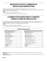
Pi_ces fournies
Pour la commande de pieces, voir la section "Pieces de
rechange".
REMARQUE : Les articles de quincaillerie presentes ci-dessous
sont destines & I'utilisation sur un colombage de bois. En
presence d'une structure de mur different, utiliser les organes de
fixation appropries.
F
}
A. Visa t_te ronde de 1/4-20x3"(6)
B. Rondelles (2)
C. Ecrous articul_s (4)
D. Vis d'ancrage 1/4" x 2" (4)
E. Garniture pour trou de passage du
cordon d'alimentation (1)
F Module de clapet anti-reflux (pour
d_charge a travers lemur ou le toit)
Composants non illustr_s :
Gabarit pour placard mural
Plaque de montage (fixation
I'arriere du four a micro-
ondes)
Filtres a graisse en
aluminium
Filtres a charbon (selon le
modele, les flltres a charbon
peuvent ne pas _tre inclus.
Voir le Guide d'utilisation et
d'entretien.)
Mat_riaux n_cessaires
• Composants standard pour decharge a travers lemur ou
travers le toit Voir la section "Specifications/conception du
circuit d'evacuation'.
Inspecter I'espace ou le four a micro-ondes sera installe.
L'emplacement d'installation dolt disposer de :
• Dimensions minimales a respecter Iors de I'installation. Voir
I'illustration "Dimensions a respecter Iors de I'installation'.
• Au moins un poteau de colombage en bois 2" x 4"
(50,8 x 101,6 mm), et parement de pl&tre ou panneau de
gypse d'epaisseur 3/8" (9,5 mm) ou plus, dans I'ouverture du
placard.
• Capacite de support de charge de 150 Ib (68 kg), ceci incluant
le four a micro-ondes et les articles places a I'interieur du four
micro-ondes et du placard mural.
• Prise de courant electrique reliee &la terre & I'int@ieur du
placard mural. Voir la section "Specifications electriques".
REMARQUES :
• Dans le cas de I'installation du four a micro-ondes a proximite
d'une paroi laterale sur le c6te gauche, veiller a laisser un
espace libre de 6" (15,2 cm) ou plus entre lemur et le four
micro-ondes, pour permettre la manoeuvre d'ouverture
complete de la porte.
• Les materiaux de certains placards et certains mat@iaux de
construction ne sont pas congus pour resister a la chaleur
emise par le four a micro-ondes Iors des op@ations de
cuisson. Consulter le constructeur de la maison ou le fabricant
des placards pour determiner si les materiaux utilises
pourraient subir un changement de couleur, une
destratification ou d'autres dommages.
Exigences sp_ciales
Pour une installation avec d_charge murale seulement :
• L'ouverture de 12" x 4" (30,5 x 10,2 cm) &decouper dolt @re
alignee avec I'ouverture rectangulaire de la plaque de
montage.
• L'ouverture decoupee dolt _tre exempte d'obstruction pour
I'ajustement adequat du conduit d'evacuation, et pour que le
clapet anti-reflux puisse manoeuvrer completement et
librement.
Pour une installation avec d_charge & I'ext_rieur & travers
le toit seulement :
• S'il est necessaire d'utiliser un raccord de transition, on dolt
disposer d'un espace libre de 3" (7,6 cm) au-dessus du four
micro-ondes pour que le clapet anti-reflux puisse manoeuvrer
completement et librement. Voir I'illustration "Raccord de
transition rectangulaire/rond" a la section "Specifications/
conception du circuit d'evacuation".
REMARQUE :Selon le modele de I'appareil, le filtre a graisse en
aluminium et le filtre a charbon peuvent _tre combines.
15