Form 400-GR (07-16) P/N 124760, page 2
Specications & illustrations subject to change without notice and without incurring obligations.
© Nortek Global HVAC, LLC 2015. All rights reserved.
All marks are the property of their respective organizations.
O’Fallon, MO I Printed in U.S.A. (7-16)
Form 400-GR (7-16), PN 124760
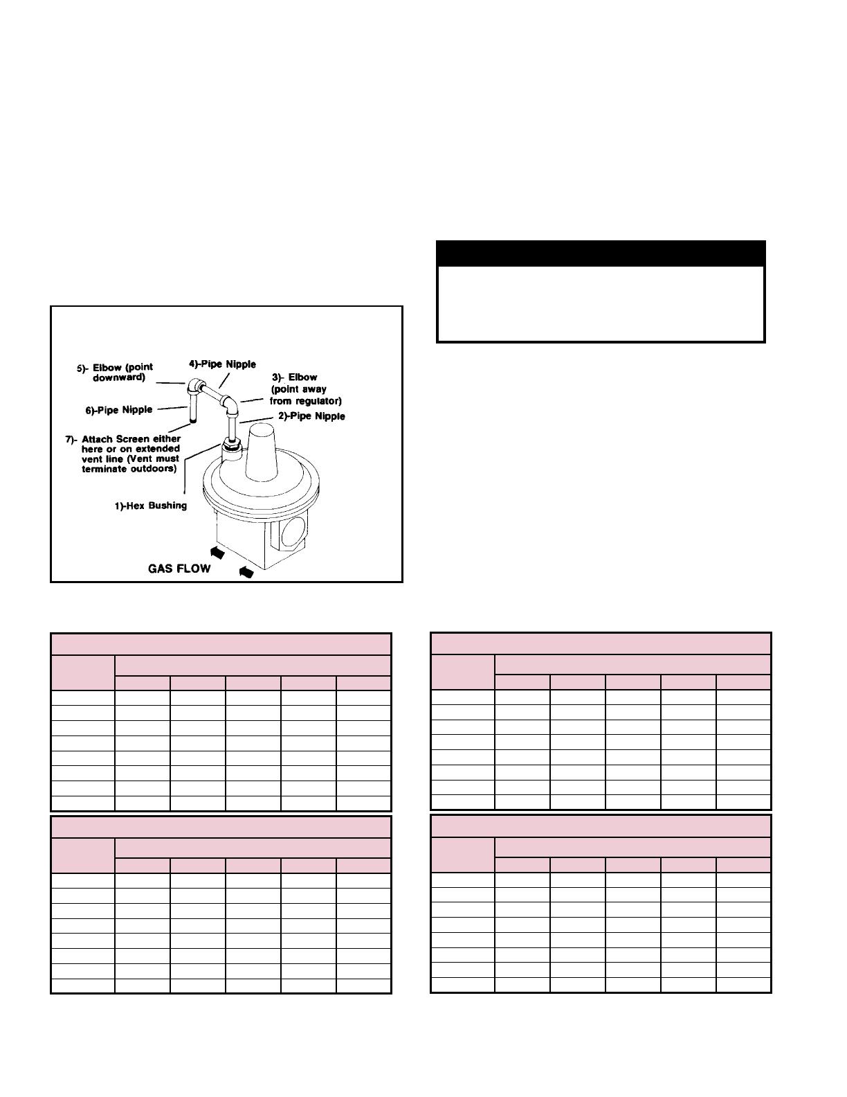
3. Install Vent Line (See Figure 1)
Remove the plastic plug from the tapped vent in
the top of the regulator. Starting at the regulator
(tapped vent) install the vent line by connecting the
pieces of pipe in the following sequence:
• Black Iron Hex Bushing
• 2-1/2” Pipe Nipple
• 90° Elbow (pointing away from the regulator)
• 2-1/2” Pipe Nipple
• 90° Elbow (pointing downward)
• 2-1/2” Pipe Nipple
Outdoor Installation - Attach plastic bug screen.
Indoor Installation - Extend vent line outdoors
using 1/8” eld-supplied piping; attach bug screen
to outdoor end of the vent line.
4. Leak Test the Gas Connections & Test the Gas
Pressure
If the unit has a gas train that includes an inlet
manifold shutoff valve, close the valve. If the gas
train does not include a manual shutoff valve
before the main control valve, disconnect & cap
the end of the gas line.
WARNING
All components of a gas supply system must
be leak tested prior to placing equipment in
service. NEVER TEST WITH AN OPEN
FLAME
High pressure testing of supply line is
acceptable, provided that the supply line has
been disconnected from the unit & the pipe
end capped.
Connect a manometer to the outlet pressure tap.
Turn on the gas supply & leak test the regulator
connections. Test using a leak-detecting solution.
Check the gas pressure reading on the manometer.
Outlet gas pressure must not be greater than 1/2
psi (14”w.c.). Outlet gas pressure may be adjusted
between 4”w.c. and 12”w.c. at the regulator.
Capacities for Spring Loaded Gas Pressure Regulators in Options CZ1 & CZ2 - Cubic Feet Per
Hour (0.64 specic gravity - natural gas).
TABLE 1 - Maxitrol Model 210DZ - 1”Pipe
Inlet
Pressure
Outlet Pressure (“w.c.)
2 4 6 9 12
8.0”w.c. 2,400 1,900 1,300 --- ---
0.5 psi 3,400 3,100 2,700 2,200 ---
0.75 psi 3,500 4,000 3,800 3,400 2,900
1.0 psi 3,500 4,000 4,500 4,300 3,900
1.5 psi 3,500 4,000 4,500 4,800 4,800
2.0 psi 3,500 4,000 4,500 4,800 4,800
3.0 psi 3,500 4,000 4,500 4,800 4,800
5.0 psi 3,500 4,000 4,500 4,800 4,800
Installation Instructions (cont’d)
TABLE 2 - Maxitrol Model 210DZ - 1-1/4”Pipe
Inlet
Pressure
Outlet Pressure (“w.c.)
2 4 6 9 12
8.0”w.c. 3,000 2,400 1,700 --- ---
0.5 psi 4,000 3,900 3,400 2,700 ---
0.75 psi 4,000 5,000 4,700 4,200 3,700
1.0 psi 4,000 5,000 5,000 5,300 4,900
1.5 psi 4,000 5,000 5,000 6,000 6,000
2.0 psi 4,000 5,000 5,000 6,000 6,000
3.0 psi 4,000 5,000 5,000 6,000 6,000
5.0 psi 4,000 5,000 5,000 6,000 6,000
Figure 1 - Install vent line on the gas regulator in the
sequence and direction illustrated (If indoor installation,
vent line must be eld extended to the outdoors).
TABLE 3 - Maxitrol Model 210EZ - 1-1/2”Pipe
Inlet
Pressure
Outlet Pressure (“w.c.)
2 4 6 9 12
8.0”w.c. 4,450 3,650 2,550 --- ---
0.5 psi 6,300 5,750 5,150 4,050 ---
0.75 psi 7,000 7,500 7,050 6,300 5,450
1.0 psi 7,000 8,800 8,500 7,950 7,250
1.5 psi 7,000 8,800 8,800 10,450 9,950
2.0 psi 7,000 8,800 8,800 10,500 10,500
3.0 psi 7,000 8,800 8,800 10,500 10,500
5.0 psi 7,000 8,800 8,800 10,500 10,500
TABLE 4 - Maxitrol Model 210EZ - 2”Pipe
Inlet
Pressure
Outlet Pressure (“w.c.)
2 4 6 9 12
8.0”w.c. 5,150 4,200 2,950 --- ---
0.5 psi 7,250 6,650 5,950 4,700 ---
0.75 psi 8,000 8,650 8,150 7,250 6,300
1.0 psi 8,000 10,000 9,850 9,150 8,400
1.5 psi 8,000 10,000 10,000 12,000 11,500
2.0 psi 8,000 10,000 10,000 12,000 12,000
3.0 psi 8,000 10,000 10,000 12,000 12,000
5.0 psi 8,000 10,000 10,000 12,000 12,000


