
User´s Guide
LXG cameras with VisualApplets
(Gigabit Ethernet)
Document Version: v1.3
Release: 03.04.17
Document Number: 11162763

2

3
Table of Contents
1. General Information ................................................................................................. 6
2. General safety instructions ..................................................................................... 7
3. Intended Use ............................................................................................................. 7
4. General Description ................................................................................................. 7
5. Camera Models ......................................................................................................... 8
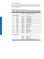
5.1 LXG – Cameras with VisualApplets ������������������������������������������������������������������������ 8
5.2 Lens Mount Adapter .............................................................................................. 10
5.3 Flange Focal Distance .......................................................................................... 12
6. Installation .............................................................................................................. 12
6.1 Environmental Requirements ................................................................................ 12
6.2 Heat Transmission ................................................................................................ 13
6.3 Mechanical Tests ................................................................................................... 14
7. Process- and Data Interface .................................................................................. 15
7.1 Pin-Assignment Interface ...................................................................................... 15
7.2 Pin-Assignment Power Supply and Digital-IOs ..................................................... 15
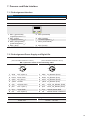
7.3 LED Signaling ....................................................................................................... 16
8. ProductSpecications .......................................................................................... 17
8.1 Sensor Specications ........................................................................................... 17
8.1.1 Quantum Efciency for Baumer LXG - Cameras with VisualApplets ������������� 17
8.1.2 Shutter ............................................................................................................ 18
8.1.3 Digitization Taps ............................................................................................ 18
8.1.4 Field of View Position ..................................................................................... 19
8.2 Timings .................................................................................................................. 20
8.2.1 Free Running Mode ........................................................................................ 20
8.2.2 Trigger Mode .................................................................................................. 21
8.2.2.1 Overlapped Operation: t
exposure(n+2)
= t
exposure(n+1) .......................... 21
8.2.2.2 Overlapped Operation: t
exposure(n+2)
> t
exposure(n+1) .......................... 22
8.2.2.3 Overlapped Operation: t
exposure(n+2)
< t
exposure(n+1) .......................... 23
8.2.2.4 Non-overlapped Operation ...................................................................... 24
9. Software .................................................................................................................. 25
9.1 Baumer GAPI SDK ............................................................................................... 25
9.2 3
rd
Party Software .................................................................................................. 25
10. Camera Functionalities .......................................................................................... 26
10.1 Image Acquisition ................................................................................................ 26
10.1.1 Image Format ............................................................................................... 26
10.1.2 Pixel Format ................................................................................................. 27
10.1.2.1 Pixel Formats on Baumer LXG - Cameras with VisualApplets �������������� 27
10.1.2.2 Denitions .............................................................................................. 27

4
10.1.3 Exposure Time.............................................................................................. 29
10.1.4 PRNU / DSNU Correction (FPN - Fixed Pattern Noise) ............................... 29
10.1.5 HDR .............................................................................................................. 30
10.1.6 Region of Interest (ROI) ............................................................................... 31
10.1.6.1 ROI Readout (Region 0) ........................................................................ 32
10.2 Analog Controls ................................................................................................... 33
10.2.1 Offset / Black Level ....................................................................................... 33
10.2.2 Gain .............................................................................................................. 33
10.3 Defect Pixel Correction ....................................................................................... 34
10.3.1 General information ...................................................................................... 34
10.3.2 Correction Algorithm ..................................................................................... 34
10.3.3 Add Defect Pixel / Defect Columns / Defect Rows to Defect pixel list .......... 35
10.4 Sequencer ........................................................................................................... 36
10.4.1 General Information ...................................................................................... 36
10.4.2 Baumer Optronic Sequencer in Camera xml-le .......................................... 37
10.4.3 Examples ...................................................................................................... 37
10.4.3.1 Sequencer without Machine Cycle ........................................................ 37
10.4.3.2 Sequencer Controlled by Machine Steps (trigger) ................................. 38
10.4.4 Capability Characteristics of Baumer GAPI Sequencer Module .................. 38
10.4.5 Double Shutter ............................................................................................. 39
10.5 Process Interface ................................................................................................ 40
10.5.1 Digital I/O ...................................................................................................... 40
10.5.1.1 I/O Circuits ............................................................................................. 40
10.5.1.2 User Denable Inputs ............................................................................ 40
10.5.1.3 Congurable Outputs ............................................................................. 41
10.6 Trigger Input / Trigger Delay ............................................................................... 42
10.6.1 Trigger Source .............................................................................................. 43
10.6.2 Debouncer .................................................................................................... 44
10.6.3 Flash Signal .................................................................................................. 44
10.6.4 Timer............................................................................................................. 45
10.7 User Sets ............................................................................................................ 46
10.8 Factory Settings .................................................................................................. 46
11. Interface Functionalities ........................................................................................ 47
11.1 Device Information .............................................................................................. 47
11.2 Baumer Image Info Header (Chunk Data)........................................................... 48
11.3 Packet Size and Maximum Transmission Unit (MTU) ......................................... 49
11.4 "Inter Packet Gap" (IPG) .................................................................................... 50
11.4.1 Example 1: Multi Camera Operation – Minimal IPG ..................................... 50
11.4.2 Example 2: Multi Camera Operation – Optimal IPG ..................................... 51
11.5 Frame Delay ........................................................................................................ 52
11.5.1 Time Saving in Multi-Camera Operation ....................................................... 52
11.5.2 Conguration Example ................................................................................. 53
11.6 Multicast .............................................................................................................. 55
11.7 IP Conguration ................................................................................................... 56
11.7.1 Persistent IP ................................................................................................. 56
11.7.2 DHCP (Dynamic Host Conguration Protocol) ............................................. 56
11.7.3 LLA ................................................................................................................ 57
11.7.4 Force IP ........................................................................................................ 57
11.8 Packet Resend .................................................................................................... 58
11.8.1 Normal Case ................................................................................................. 58
11.8.2 Fault 1: Lost Packet within Data Stream ....................................................... 58
11.8.3 Fault 2: Lost Packet at the End of the Data Stream ..................................... 59
11.8.4 Termination Conditions ................................................................................ 59

5
11.9 Message Channel ............................................................................................... 60
11.10 Action Commands ............................................................................................. 61
11.10.1 Action Command Trigger ............................................................................ 61
12. Start-Stop-Behaviour ............................................................................................. 62
12.1 Start / Stop Acquisition (Camera) ........................................................................ 62
12.2 Start / Stop Interface ........................................................................................... 62
12.3 Pause / Resume Interface .................................................................................. 62
12.4 Acquisition Modes ............................................................................................... 62
12.4.1 Free Running ................................................................................................ 62
12.4.2 Trigger .......................................................................................................... 62
12.4.3 Sequencer .................................................................................................... 62
13. Cleaning .................................................................................................................. 63
13.1 Sensor ................................................................................................................. 63
13.2 Cover glass ......................................................................................................... 63
13.3 Housing ............................................................................................................... 63
14. Transport / Storage ................................................................................................ 64
15. Disposal .................................................................................................................. 64
16. Warranty Information ............................................................................................. 64
17. Conformity .............................................................................................................. 65
17.1 CE ....................................................................................................................... 65
18. Support .................................................................................................................... 65

6
1. General Information
Thanks for purchasing a camera of the Baumer family. This User´s Guide describes how
to connect, set up and use the camera.
Read this manual carefully and observe the notes and safety instructions!
Target group for this User´s Guide
This User's Guide is aimed at experienced users, which want to integrate camera(s) into
a vision system.
Copyright
Any duplication or reprinting of this documentation, in whole or in part, and the reproduc-
tion of the illustrations even in modied form is permitted only with the written approval of
Baumer. This document is subject to change without notice.
Classicationofthesafetyinstructions
In the User´s Guide, the safety instructions are classied as follows:
Notice
Gives helpful notes on operation or other general recommendations.
Caution
Pictogram
Indicates a possibly dangerous situation. If the situation is not avoided,slight
or minor injury could result or the device may be damaged.

7
2. General safety instructions
Observe the the following safety instruction when using the camera to avoid any damage
or injuries.
Caution
Provide adequate dissipation of heat, to ensure that the temperature does
not exceed +50 °C (+122 °F).
The surface of the camera may be hot during operation and immediately
after use. Be careful when handling the camera and avoid contact over a
longer period.
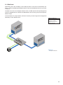
3. Intended Use
The camera is used to capture images that can be transferred over a GigE interface to a
PC.
Notice
Use the camera only for its intended purpose!
For any use that is not described in the technical documentation poses dangers and will
void the warranty. The risk has to be borne solely by the unit´s owner.
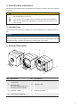
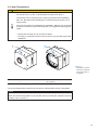
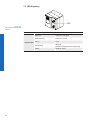
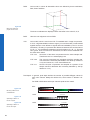
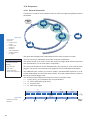
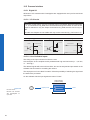
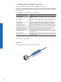
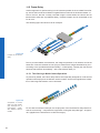
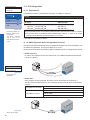
4. General Description
1
2
3
4
5
No. Description No. Description
1
LXG-20 / 40
C-mount only.
LXG-120 / 200
lens mount (M58), adapter for
other lens mounts available
4 Signaling LED
2 Data Port 1 (PoE) 5 Digital-IO (RS485)
3 Power Suppy / Digital-IO

8
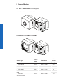
5. Camera Models
5.1 LXG – Cameras with VisualApplets
LXG-20M.PS / LXG-20C.P / LXG-40M.P
LXG-120M.PS / LXG-120M.P / LXG-200M.P
Camera Type
Sensor
Size
Resolution
Full
Frames
1)
[max. fps]
Monochrome
LXG-20M.PS 2/3" 2018 × 1088 338
LXG-40M.P 1" 2048 × 2048 74
LXG-120M.PS APS-C 4096 × 3072 60
LXG-120M.P APS-C 4096 × 3072 25
LXG-200M.P 35 mm 5120 × 3840 16
Color
LXG-20C.P 2/3" 2048 × 1088 140
1)
sensor frame rate

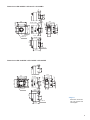
9
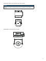
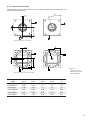
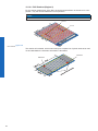
Dimensions LXG-20M.PS / LXG-20C.P / LXG-40M.P
60
60
47
47
Pixel 0,0
8 x M3 x 6
1"-32 UN
18,055 ±0,025
26
8
52,35
54,25
44,75
8
26
8 x M3 x 6
8
26
30
6
19,7
20
17,5
48,8
14,7
14,7
35,8
Dimensions LXG-120M.PS / LXG-120M.P / LXG-200M.P
47
60
47
60
M58 x 0,75
Pixel 0,0
4 x M3 x 6
44,75
52,35
54,25
35,8
8
26
8 x M3 x 6
8
26
12 ±0,25
8
26
14,7
19,7
20
17,5
48,8
14,7
◄Figure1
Dimensions of the Bau-
mer LXG cameras with
VisualApplets

10
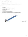
5.2 Lens mount Adapter
Adapter M58 / F-mount (Art. No.: 11117852)
59ø
40,43
F-Mount
M58x0,75
Adapter M58 / M42x1-mount (26.8mm) (Art. No.: 11127232)
Notice
suitable for Zeiss M42 lenses (e.g. Biogon T* 2.8/21 Z-M42-I, Biogon T* 2/35 Z-M42-I,
C Sonnar T* 1.5/50 Z-M42-I)
20,75
59ø
M58x0,75
M42x1
3
ø
50

11
Adapter M58 / M42x1-mount (45.5 mm) (Art. No: 11137781)
Notice
suitable for Zeiss (e.g. Distagon T* 2/25 Z-M42-I, Planar T* 1.4/50 Z-M42-I, Makro-
Planar T* 2/50 Z-M42-I) and KOWA M42 lenses (e.g. LM28LF P-mount, LM35LF
P-mount)
39,43
59ø
M58x0,75
M42x1
3
ø
50
Adapter M58 / C-mount (Art. No: 11115198)
C-Mount
M58x0,75
59ø
30ø
4,467
3ø
50

12
5.3 Flange Focal Distance
12 ±0,25
6. Installation
Lens mounting
Notice
Avoid contamination of the sensor and the lens by dust and airborne particles when
mounting the support or the lens to the device!
Therefore the following points are very important:
▪ Install the camera in an environment that is as dust free as possible!
▪ Keep the dust cover (foil) on camera as long as possible!
▪ Hold the print with the sensor downwards with unprotected sensor.
▪ Avoid contact with any optical surface of the camera!
6.1 Environmental Requirements
Temperature
Storage temperature -10 °C ... +70 °C ( +14 °F ... +158 °F)
Operating temperature* see Heat Transmission
* If the environmental temperature exceeds the values listed in the table below, the cam-
era must be cooled. (see Heat Transmission)
Humidity
Storage and Operating Humidity 10 % ... 90 %
Non-condensing

13
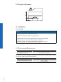
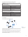
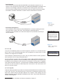
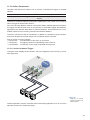
6.2 Heat Transmission
Caution
Provide adequate dissipation of heat, to ensure that the temperature does
not exceed +50 °C (+122 °F) at temperature measurment point T.
The surface of the camera may be hot during operation and immediately
after use. Be careful when handling the camera and avoid contact over a
longer period.
As there are numerous possibilities for installation, Baumer do not speciy
a specic method for proper heat dissipation, but suggest the following prin-
ciples:
▪ operate the cameras only in mounted condition
▪ mounting in combination with forced convection may provide proper heat
dissipation
T
T
Measure Point Maximal Temperature
T 50 °C (122 °F)
For remote temperature monitoring of the camera a temperature sensor is integrated.
Notice
The temperature sensor is able to deliver values of 0 °C (32 °F) to +85 °C (185 °F)
Take care that the temperature of the camera does not exceed the specied case tem-
perature +50 °C (+122 °F).
◄Figure2
Temperature measure-
ment points of Baumer
LXG cameras with Vi-
sualApplets�

14
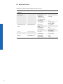
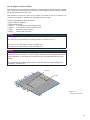
6.3 Mechanical Tests
Tested with C-Mount adapter adapter and lens dummy.
Environmental
Testing
Standard Parameter
Vibration,
sinussodial
IEC 60068-2-6 Search for
Resonance
10-2000 Hz
Amplitude un-
derneath cross-
over frequencies
0,75 mm
Acceleration 1 g
Test duration 15 min (axis)
45 min (total)
Vibration, broad
band
IEC 60068-2-64 Frequency
range
10-1000 Hz
Acceleration 10 g
Test duration 300 min (axis)
15 h (total)
Shock IEC 60068-2-27 Puls time 11 ms / 6 ms
Acceleration 50 g / 100 g
Bump IEC60068-2-29 Pulse Time 2 ms
Acceleration 100 g

15
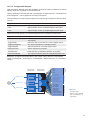
7. Process- and Data Interface
7.1 Pin-Assignment Interface
Notice
The Data Port supports Power over Ethernet (36 VDC .. 57 VDC).
Data / Control 1000 Base-T
LED2
LED1
8
1
1 MX1+ (green/white)
(negative/positive V
port
)
5 MX3- (blue/white)
2 MX1- (green)
(negative/positive V
port
)
6 MX2- (orange)
(positive/negative V
port
)
3 MX2+ (orange/white)
(positive/negative V
port
)
7 MX4+ (brown/white)
4 MX3+ (blue) 8 MX4- (brown)
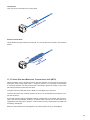
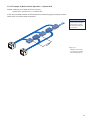
7.2 Pin-Assignment Power Supply and Digital-IOs
Power and Process Interface #1
(SACC-DSI-M8FS-8CON-M10-L180 SH)
Power and Process Interface #2
(SACC-DSI-M8MS-8CON-M8-L180 SH)
M8 / 8 pins wire colors of the connecting cable
8
5
7
3
1
4
2
6
8
5
7
3
1
4
2
6
1 white OUT 3 (line 3) 1 white In2_RS485+ (line4)
2 brown Power VCC+ 2 brown In2_RS485- (line4)
3 green IN 1 (line 0) 3 green In2_RS485+ (line5)
4 yellow IO GND 4 yellow In2_RS485- (line5)
5 grey IO Power VCC 5 grey OUT3_In2_RS485+ (line6)
6 pink OUT 1 (line 1) 6 pink OUT3_In2_RS485- (line6)
7 blue Power GND 7 blue external Power GND
8 red OUT 2 (line 2) 8 red external Power 5 V/200 mA
Power Supply
Power VCC 12 VDC ... 24 VDC

16
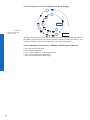
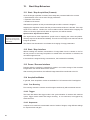
7.3 LED Signaling
LED
Signal Meaning
Camera LED
green on Power on, link good
green blinking Power on, no link
red on Error
red blinking
Warning
(update in progress, don’t switch off)
yellow Readout active
Figure3►
LED positions on Baumer LXG
cameras.

17
8. ProductSpecications
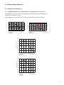
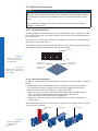
8.1 SensorSpecications
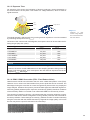
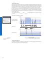
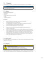
8.1.1 QuantumEfciencyforBaumerLXG-CameraswithVisualApplets
The quantum efciency characteristics of Baumer LXG - cameras with VisualApplets are
displayed in the following graphs.
Values relating to the respective technical data sheets of the sensors manufacturer.
0
10
20
30
40
50
60
70
400500 600 700 800 900 1000
Quantum efficiency [%]
Wave Length [nm]
LXG-20M.PS
(CMV2000 V3)
0
10
20
30
40
50
60
300400 500 600 700800 900 1000 1100
Quantum Efficiency [%]
Wavelength [nm]
LXG-20C.P
(CMV2000 V3)
350 450 550 650 750 850 950 1050
Wave Length [nm]
Quantum Efficiency [%]
LXG-40M.P
(CMV4000 V3)
350 450 550 650 750 850 950 1050
Wave Length [nm]
Quantum Efficiency [%]
LXG-120M.P
LXG-120M.PS
(CMV12000)

18
350450 550650 750850 9501050
Wave Length [nm]
Quantum Efficiency [%]
LXG-200M.P
(CMV-20000)
Mono
70
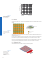
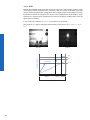
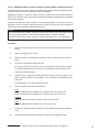
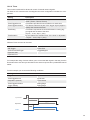
8.1.2 Shutter
All cameras of the LXG - camera with VisualApplets series are equipped with a global
shutter.
Pixel
Active Area (Photodiode)
Storage Area
Microlens
Global shutter means that all pixels of the sensor are reset and afterwards exposed for a
specied interval (t
exposure
).
For each pixel an adjacent storage circuit exists. Once the exposure time elapsed, the
information of a pixel is transferred immediately to its circuit and read out from there.
Due to the fact that photosensitive area gets "lost" by the implementation of the circuit
area, the pixels are equipped with microlenses, which focus the light on the pixel.
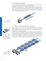
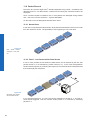
8.1.3 Digitization Taps
The CMOSIS sensors are read out with 16 channels in parallel.
Figure4►
Quantum efciency for
Baumer LXG cameras
with VisualApplets�
Figure5►
Structure of an imag-
ing sensor with global
shutter
Figure6►
Digitization Tap of the
Baumer LXG cam-
eras with VisualAp-
plets Readout with 16
channel

19
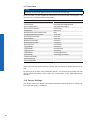
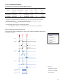
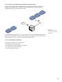
8.1.4 Field of View Position
The typical accuracy by assumption of the root mean square value is displayed in the
gures and the table below:
±
β
A'
A
A'
A
±Y
±X
±X
±Y
M
M
R
R
LXG-20C.P / LXG-20M.P / LXG-40M.P
A'
A
±Y
±X
±X
±Y
M
M
R
R
β
A'
A
LXG-120M.PS / LXG-120M.P / LXG-200M.P
Camera
Type
± x
M,typ
[mm]
± y
M,typ
[mm]
± x
R,typ
[mm]
± y
R,typ
[mm]
± β
typ
[°]
LXG-20C.P 0.09 0.09 0.1 0.1 0.4
LXG-20M.PS 0.09 0.09 0.1 0.1 0.4
LXG-40M.P 0.09 0.09 0.1 0.1 0.4
LXG-120M.PS 0.07 0.06 0.08 0.07 0.26
LXG-120M.P 0.07 0.06 0.08 0.07 0.26
LXG-200M.P 0.08 0.08 0.09 0.08 0.27
◄Figure7
Sensor accuracy of
Baumer LXG cameras
with VisualApplets�

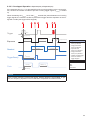
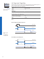
20
8.2 Timings
Notice
Overlapped mode can be switched off with setting the readout mode to sequential shut-
ter instead of overlapped shutter.
The image acquisition consists of two separate, successively processed components.
Exposing the pixels on the photosensitive surface of the sensor is only the rst part of the
image acquisition. After completion of the rst step, the pixels are read out.
Thereby the exposure time (t
exposure
) can be adjusted by the user, however, the time need-
ed for the readout (t
readout
) is given by the particular sensor and image format.
Baumer cameras can be operated with two modes, the Free Running Mode and the
Trigger Mode.
The cameras can be operated non-overlapped
1)
or overlapped. Depending on the mode
used, and the combination of exposure and readout time:
Non-overlapped Operation Overlapped Operation
Here the time intervals are long enough
to process exposure and readout succes-
sively.
In this operation the exposure of a frame
(n+1) takes place during the readout of
frame (n).
Exposur
e
Readout
Exposur
e
Readout
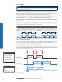
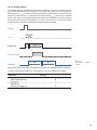
8.2.1 Free Running Mode
In the "Free Running" mode the camera records images permanently and sends them to
the PC. In order to achieve an optimal (with regard to the adjusted exposure time t
exposure
and image format) the camera is operated overlapped.
In case of exposure times equal to / less than the readout time (t
exposure
≤ t
readout
), the maxi-
mum frame rate is provided for the image format used. For longer exposure times the
frame rate of the camera is reduced.
Exposur
e
Readout
Flas
h
t
exposure(n)
t
flash(n)
t
flashdelay
t
flash(n+1)
t
readout(n+1)
t
readout(n)
t
exposure(n+1)
t
ash
= t
exposure
1) Non-overlapped means the same as sequential.
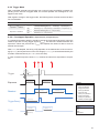
Image parameters:
Offset
Gain
Mode
Partial Scan
Timings:
A - exposure time
frame (n) effective
B - image parameters
frame (n) effective
C - exposure time
frame (n+1) effective
D - image parameters
frame (n+1) effective
Page is loading ...
Page is loading ...
Page is loading ...
Page is loading ...
Page is loading ...
Page is loading ...
Page is loading ...
Page is loading ...
Page is loading ...
Page is loading ...
Page is loading ...
Page is loading ...
Page is loading ...
Page is loading ...
Page is loading ...
Page is loading ...
Page is loading ...
Page is loading ...
Page is loading ...
Page is loading ...
Page is loading ...
Page is loading ...
Page is loading ...
Page is loading ...
Page is loading ...
Page is loading ...
Page is loading ...
Page is loading ...
Page is loading ...
Page is loading ...
Page is loading ...
Page is loading ...
Page is loading ...
Page is loading ...
Page is loading ...
Page is loading ...
Page is loading ...
Page is loading ...
Page is loading ...
Page is loading ...
Page is loading ...
Page is loading ...
Page is loading ...
Page is loading ...
Page is loading ...
Page is loading ...
-
 1
1
-
 2
2
-
 3
3
-
 4
4
-
 5
5
-
 6
6
-
 7
7
-
 8
8
-
 9
9
-
 10
10
-
 11
11
-
 12
12
-
 13
13
-
 14
14
-
 15
15
-
 16
16
-
 17
17
-
 18
18
-
 19
19
-
 20
20
-
 21
21
-
 22
22
-
 23
23
-
 24
24
-
 25
25
-
 26
26
-
 27
27
-
 28
28
-
 29
29
-
 30
30
-
 31
31
-
 32
32
-
 33
33
-
 34
34
-
 35
35
-
 36
36
-
 37
37
-
 38
38
-
 39
39
-
 40
40
-
 41
41
-
 42
42
-
 43
43
-
 44
44
-
 45
45
-
 46
46
-
 47
47
-
 48
48
-
 49
49
-
 50
50
-
 51
51
-
 52
52
-
 53
53
-
 54
54
-
 55
55
-
 56
56
-
 57
57
-
 58
58
-
 59
59
-
 60
60
-
 61
61
-
 62
62
-
 63
63
-
 64
64
-
 65
65
-
 66
66


Baumer LXG-120M.P User guide
- Type
- User guide
- This manual is also suitable for
Ask a question and I''ll find the answer in the document
Finding information in a document is now easier with AI
Related papers
-
Baumer LXG-200C User guide
-
Baumer HXG40c User guide
-
Baumer VLG-22C.I User guide
-
Baumer VLG-20M User guide
-
Baumer MXGC20c User guide
-
-
-
-
-
Baumer HXC40c Operating instructions
Other documents
-
PYLE Audio UPDBC10 User manual
-
Paasche LXG-14 User manual
-
 SVS-Vistek eco415 User manual
-
Basler Complete VisualApplets User manual
-
JAI SW-2000M-CL-65 User manual
-
 opto engineering COE-290 User manual
-
Quantum Vision Quick start guide
-
Zeiss Axiocam 512 color User manual
-
Advantech AIIS-1750 User manual
-
AMS CMV4000 EVALUATION KIT User guide

