Page is loading ...

RTB Tubing Bundles Installation
Guide
Heating Solutions for Instrument and Small-Diameter
ProcessLines

2 | nVent.com
WARNING:
Fire and shock hazard.
nVent RAYCHEM heat-tracing systems must be installed correctly to ensure proper operation and
to prevent shock and fire. Read these important warnings and carefully follow all the installation
instructions.
• To minimize the danger of fire from sustained electrical arcing if the heating cable is damaged
or improperly installed, and to comply with nVent requirements, agency certifications, and the
national electrical codes, ground-fault equipment protection must be used on each heating-
cable branch circuit. Arcing may not be stopped by conventional circuit breakers.
• Approvals and performance of the heat-tracing systems are based on the use of nVent
specified parts only. Do not substitute parts or use vinyl electrical tape.
• Bus wires will short if they contact each other. Keep bus wires separated.
• Components and cable ends must be kept dry before and during installation.
• The black heating-cable core and fibers are conductive and can short. They must be properly
insulated and kept dry.
• Damaged bus wires can overheat or short. Do not break bus wire strands when preparing the
cable for connection.
• Damaged heating cable can cause electrical arcing or fire. Do not use metal attachments such
as pipe straps or tie wire. Use only nVent-approved tapes and cable ties to secure the cable to
the pipe.
• Do not attempt to repair or energize damaged cable. Remove damaged cable at once
and replace with a new length using the appropriate nVent splice kit. Replace damaged
components.
• Re-use of the grommets, or use of the wrong grommet, can cause leaks, cracked components,
shock, or fire. Be sure the type of grommet is correct for the heating cable being installed. Use
a new grommet whenever the cable has been pulled out of the component.
• Use only fire-resistant insulation which is compatible with the application and the maximum
exposure temperature of the system to be traced.
• To prevent fire or explosion in hazardous locations, verify that the maximum sheath
temperature of the heating cable is below the auto-ignition temperature of the gases in the
area. For further information, see the design documentation.
• Material Safety Data Sheets (MSDSs) are available from the nVent Customer Service Center,
and at nVent.com.

nVent.com | 3
CONTENTS
1. General Information ................................................................................................................................... 4
1.1 Use of the Manual ............................................................................................................................. 4
1.2 Safety Guidelines .............................................................................................................................. 4
1.3 Electrical Codes ................................................................................................................................ 4
1.4 Warranty and Approvals ................................................................................................................... 4
2. Introduction ................................................................................................................................................ 5
2.1 Product Line ...................................................................................................................................... 5
2.2 System Overview .............................................................................................................................. 6
2.3 Tubing Bundle Catalog Number ....................................................................................................... 7
2.4 Bundle Materials ............................................................................................................................... 7
3. Verify Product Selection ............................................................................................................................. 8
3.1 Heater Type and Temperature Range .............................................................................................. 8
3.2 Electrical Sizing and Run Length ..................................................................................................... 9
3.3 Select Components ........................................................................................................................ 11
3.4 Select Bundle Accessories............................................................................................................. 11
4. Installation ............................................................................................................................................... 13
4.1 Description ...................................................................................................................................... 13
4.2 Weights and Dimensions ............................................................................................................... 13
4.3 Storage ............................................................................................................................................ 14
4.4 Positioning and Support ................................................................................................................. 14
4.5 Uncoiling and Bending.................................................................................................................... 15
4.6 Electric Trace-Heating Connections .............................................................................................. 15
4.7 Bundle Sealing ................................................................................................................................ 17
4.9 Thermostat Jacket Patch ............................................................................................................... 18

4 | nVent.com
1. GENERAL INFORMATION
1.1 USE OF THE MANUAL
This installation and maintenance manual is for nVent RAYCHEM RTB Tubing Bundles systems only.
For information regarding other applications, design assistance or technical support, contact your
nVent representative or nVent directly.
nVent
899 Broadway Street
Redwood City, CA 94063
USA
Tel (800) 545-6258
Fax (800) 527-5703
nVent.com
Important: For the nVent warranty and agency approvals to apply, the instructions that are
included in this manual and product packages must be followed.
1.2 SAFETY GUIDELINES
The safety and reliability of any heat-tracing system depends on proper design, installation and
maintenance. Incorrect handling, installation, or maintenance of any of the system components
can cause underheating or overheating of the pipe or damage to the heating-cable system and
may result in system failure, electric shock or fire.
1.3 ELECTRICAL CODES
Sections 427 (pipelines and vessels) and 500 (classified locations) of the National Electrical
Code (NEC), and Part 1 of the Canadian Electrical Code, Sections 18 (hazardous locations) and
62 (Fixed Electric Space and Surface Heating), govern the installation of electrical heat-tracing
systems. All heat-tracing-system installations must be in compliance with these and any other
applicable national or local codes.
1.4 WARRANTY AND APPROVALS
The RTB system uses nVent RAYCHEM BTV and XTV heating cables that are approved and
certified for use in nonhazardous and hazardous locations by many agencies, including FM
Approvals, CSA International, PTB, Baseefa (2001) Ltd., DNV, and ABS. For more details, consult
the heating cable data sheets included in the Industrial Heating Product and Design Guide
(H56550) and the Technical Databook for Industrial Heat-Tracing Systems (DOC-389). Data sheets
can be found on the nVent web site, nVent.com.
IMPORTANT WARNINGS AND NOTES
The following icons are used extensively throughout this manual to alert you to important
warnings
that affect safety and to important notes that affect the proper operation of the
unit. Be sure to read and follow them carefully.

nVent.com | 5
2. INTRODUCTION
nVent provides a total solution for heat tracing instrument and small-diameter process lines.
RAYCHEM tubing bundles (RTB) are a pretraced and preinsulated tubing alternative to field tracing
and insulating. RTB systems combine RAYCHEM electric or steam heat tracing with tubing and
insulation for a single bundle that can be cut to length in the field.
Typical RTB applications include:
• Impulse lines - to flow transmitters, pressure transmitters, level transmitters, and pressure
switches
• Sample lines - to analyzers and chromatographs
• Process lines - for steam supply, condensate return, water purge, chemical feed, and air lines
For European systems, the following nVent literature should be reviewed in order to complete the
design and installation of RTB Tubing Bundles systems:
• Installation and Maintenance Manual (DOC-071)
• Components Selection Guide (DOC-565-R1)
• Electrical Protection Bulletin (DOC-057)
• Technical Data Book for Industrial Heat-Tracing Systems (DOC-389-R10)
For North American systems, the following nVent literature should be reviewed in order to
complete the design and installation of RTB Tubing Bundles systems:
• Installation and Maintenance Guide (H57274)
• Design Guide for Insulated Pipes and Tubing (H56882)
This literature is available from your nVent representative.
2.1 PRODUCT LINE
Tubing bundles
RTB tubing bundles are available in a wide range of tubing and heater options (see bundle ordering
options on page 7).
Trace-heating components
RTB tubing bundles use the full range of XTV and BTV power connection and end seal kits.
Bundle accessories
RTB bundle accessories include heat-shrinkable boots for sealing bundle ends, heat-shrinkable
cable entry seals, a jacket patch kit for sealing around thermostat sensor entries, and a high-
temperature silicone sealant for sealing bundle ends.

6 | nVent.com
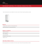
2.2 SYSTEM OVERVIEW
An RTB system consists of pretraced and preinsulated tubing bundles. Each tubing bundle can be
configured as single- or dual-tube, as shown below, and can be constructed in various sizes and
materials to meet your small-diameter process piping needs.
Figure 1 Tubing bundles, single and dual-tube construction
RAYCHEM tubing bundles (RTB) are pre-engineered to ensure consistent and repeatable
performance for maintenance-free operation. Compared to field fabrication, they simplify design
and significantly reduce installation time. Each bundle can be cut to length in the field and is
powered and terminated with simple RTB connection kits. The insulating material consists of a
nonhygroscopic fibrous glass for maximum heat-loss prevention. Finally, each RTB is encased in a
high-performance polyurethane outer jacket that provides superior UV resistance and installation
capability to -40°C (-40°F).
Contact your nVent representative for design assistance for the following applications:
• The desired maintain temperature range or process tube size does not appear in Table 1 on
page 8, Table 2 on page 9, or Table 3 on page 10
• The ambient temperature range is not between -30°C to 38°C (-20°F to 100°F)
• Supply voltages of 208 Vac and 277 Vac are used
Single-tube
Dual-tube
Rugged outer jacket
Nonhygroscopic
fibrous insulation
Heating cable

nVent.com | 7
2.3 TUBING BUNDLE CATALOG NUMBER
RTB comes in a variety of configurations. The following chart outlines the elements that constitute
a bundle configuration and the corresponding catalog number. Other configurations are available
on request.
RTB* - X - XXX - X - XXX - XXX-X**
Electric Traced heating options
5B1 = 5BTV1-CT
8B1 = 8BTV1-CT
10B1 = 10BTV1-CT
5B2 = 5BTV2-CT
8B2 = 8BTV2-CT
10B2 = 10BTV2-CT
5X1 = 5XTV1-CT-T3
10X1 = 10XTV1-CT-T3
15X1 = 15XTV1-CT-T2
20X1 = 20XTV1-CT-T2
5X2 = 5XTV2-CT-T3
10X2 = 10XTV2-CT-T3
15X2 = 15XTV2-CT-T3
20X2 = 20XTV2-CT-T2
Process tube wall thickness
030 = 0.030 in 10 = 1.0 mm
032 = 0.032 in 15 = 1.5 mm
035 = 0.035 in
049 = 0.049 in
062 = 0.062 in
065 = 0.065 in
Process tube material
S = Seamless 316 SS M = Monel P = PFA
W = Welded 316 SS C = Copper
Process tubing size
1/8 = 1/8 in 6 = 6 mm
1/4 = 1/4 in 8 = 8 mm
3/8 = 3/8 in 10 = 10 mm
1/2 = 1/2 in 12 = 12 mm
3/4 = 3/4 in
Number of process tubes
1 = Single-tube
2 = Dual-tube
Steam Traced heating options
LTS = Low-temperature steam
HTS = High-temperature steam
Preinsulated Only
PIO = Preinsulate only
Examples:
Electric Traced RTB-2-1/2-S-049-10X1
Steam Traced RTB-2-1/2-S-049-LTS-3/8-C-035
Preinsulated Only RTBC-1-1/2-S-049-PIO
* For optional Arctic PVC jacket, add suffix "C" example RTBC
** Requires the selection of tubing size = XX, tubing material = X,
and wall thickness = XXX for both LTS and HTS
2.4 BUNDLE MATERIALS
Bundle jacket
• Thermoplastic polyether urethane elastomer
• Halogen-free
• Abrasion resistant
• UV-resistant
• Low-temperature flexibility
• Optional artic PVC
Thermal insulation
• Fibrous glass
• Water-soluble chlorides less than 100 ppm
• Non-hygroscopic
Tubing
• Welded stainless steel tubing complies with ASTM A-269.
• Seamless stainless steel tubing complies with ASTM A-269 and A213-EAW.
• Metric tubing sizes provided with inspection certificate per EN10204.

8 | nVent.com
3. VERIFY PRODUCT SELECTION
3.1 HEATER TYPE AND TEMPERATURE RANGE
Table 1 shows the minimum and maximum temperatures that can be maintained by the process
tube over an ambient temperature range of -30°C to 38°C (-20°F to 100°F).
• In Table 1, find the column for the desired process tube size. Within the column, find the
heater(s) that maintains a minimum temperature at or above the desired maintain temperature.
• If more than one heating cable will maintain the temperature, choose the one with the lowest
maximum temperature. Make sure that:
• The T-rating of the heating cable is adequate
• Only XTV is used if the maximum system exposure temperature is above 85°C (185°F)
• A thermostat will be used if the maximum temperature in the table is higher than desired
set point
Table 1: Process Tube Maintain Temperatures (Minimum-Maximum) for Ambient Range of -30°C to
38°C (-20°F to 100°F ) at 120/240 V
Contact your nVent representative for design assistance for the following applications:
• The desired maintain temperature range or process tube size does not appear in Table 1 on
page 8, Table 2 on page 9, or Table 3 on page 10
• The ambient temperature range is not between -30°C to 38°C (-20°F to 100°F)
• Supply voltages of 208 Vac and 277 Vac are used
6 mm or 1/4 in 8 mm 3/8 in 10 mm 12 mm or 1/2 in
°C (°F) °C (°F) °C (°F) °C (°F) °C (°F)
Single-tube
Heater Type Tubing Size
5BTV1 and 219–52 (66–126) 18–52(64–125) 16–51(61–124) 15–51(60–123)14–50 (58–122)
8BTV1 and 232–58 (90–136) 31–57(88–135) 29–57(85–134) 28–56(83–134)27–56 (81–133)
5XTV1 and 231–92 (87–197) 28–90(82–194) 26–88(78–190)23–87 (74–189) 21–84(70–184)
10XTV1 and 263–110(145–231) 60–108 (139–226)56–105(133–222) 53–105 (128–220)51–101(123–214)
15XTV1 and 284–126*(184–250)* 81–123*(177–250)*78–120(172–248)77–120(170–247) 71–116 (161–240)
20XTV1 and 2111–151*(232–250)* 107–148*(224–250)*103–145*(217–250)*102–144*(215–250)*96–139* (204–250)*
Dual-tube
5BTV1 and 218–52 (64–125) 16–51(61–124) 14–50(58–122) 13–49(56–121)12–49 (53–120)
8BTV1 and 232–58 (89–136) 30–57(86–135) 28–56(82–133) 26–56(79–132)24–55 (76–131)
5XTV1 and 229–91 (85–196) 25–88(77–190) 22–85(71–184)19–84 (66–183) 16–80(60–176)
10XTV1 and 261–109(142–228) 56–105 (133–221)52–102(125–215) 48–101 (119–213)44–96 (112–205)
15XTV1 and 283–124*(181–250)* 77–119 (171–247)73–116(162–241)71–115(160–240) 64–110(148–230)
20XTV1 and 2109–149* (228–250)* 102–144*(216–250)*97–140* (206–250)* 95–139*(203–250)*87–132* (189–250)*
The temperatures included in Table 1 are approximate. For critical applications contact your nVent representative.
* Requires overtemperature line-sensing thermostat to ensure operation below maximum continuous exposure temperature of the heating cable.

nVent.com | 9
3.2 ELECTRICAL SIZING AND RUN LENGTH
Tables 2 and 3 show the maximum bundle length that may be powered from different sized
circuit breakers. Use Table 2 for European type circuit breakers. Use Table 3 for North American
circuit breakers. Note that ground-fault equipment protection (residual current device) is required
on each heating cable branch circuit. To reduce the risk of fire caused by damage or improper
installation, circuit breakers with a 30-mA trip level must be used. Alternative designs providing
comparable levels of ground-fault protection may also be acceptable. Contact your nVent
representative for assistance if you need to size circuit breakers for use under different start-up
conditions. For maximum protection, use the smallest circuit breaker consistent with the length of
heating cable installed.
Table 2: Maximum Circuit Length vs. Circuit Breaker Rating: 120 Vac
Start-up temp. 15 A20 A30 A 40
A5
0 A
°C °F mftmft mftmft
mf
t
10 50 55 180 73 240110 360117 385117 3855XTV1-CT-T3
–18049 16064210 98 320117 385117 385
–29–20 46 15061 200 93 305117 385117 385
–40–40 44 14559 195 88 290117 385117 385
10XTV1-CT-T3 10 50 34 110 44 145 67 22082270 82 270
–18029 95 40 13059195 79 26082270
–29–20 29 95 38 12558190 76 25082270
–40–40 27 90 37 12055180 73 24082270
15XTV1-CT-T2 10 50 23 75 30 10046150 61 20067220
–18020 65 27 90 41 13555180 67 220
–29–20 20 65 26 85 40 13052170 66 215
–40–40 18 60 24 80 38 12550165 62 205
20XTV1-CT-T2 10 50 15 502637 12049160 58 190
–18015 50 21 70 32 10543140 55 180
–29–20 15 50 20 65 32 10543140 52 170
–40–40 15 50 20 65 30 10040130 50 165
5BTV1-CT 10 50 70 23082 270 82 27082270 **
–18043 14058190 82 27082270 **
–29–20 38 12550 165 76 25082270
**
–40–40 34 11044 145 67 22082270
**
8BTV1-CT 10 50 46 15061 200 64 21064210 **
–18030 10040130 61 20064210 **
–29–20 26 85 35 11553175 64 210* *
–40–40 24 80 32 10547155 64 210* *
10BTV1-CT105037120 49 16055180 55 180* *
–18024 80 34 11049160 55 180* *
–29–20 21 70 29 95 43 14055180
**
–40–40 20 65 26 85 38 12552170
**
Heating Cable
* For these design conditions, use a smaller circuit breaker or alternate heating cable.

10 | nVent.com
Start-up temp. 15 A 20 A 30 A40
A5
0 A
°C °F mftmft mftmft mft
10 50 110360 146480 219 720233 765233 765
–18096 315128 420191 625 233 765 233765
–29–20 90 295120 395181 595233 765 233 765
–40–40 87 285116 380174 570232 760 233 765
10XTV2-CT-T3 10 50 67 22090295 134 440 165540 165540
–18059 19579260 117385 157515 165 540
–29–20 56 18575245 113370 151495 165540
–40–40 53 17572235 108355 143470 165540
15XTV2-CT-T3 10 50 46 15061200 91 300122 400 136445
–18040 13053175 81 265108 355134 440
–29–20 38 12550165 76 250102 335128 420
–40–40 37 12049160 73 24098320 123405
10 50 35 11546150 70 230162 530 116 380
–18030 10041135 62 20584275 105345
–29–20 30 10040130 61 20081265 101330
–40–40 29 95 38 12558190 78 25598320
5BTV2-CT 10 50 140460 165540 165 540165 540* *
–18087 285116 380165 540 165 540 **
–29–20 76 250101 330152 500165 540* *
–40–40 67 22090295 134440 165540
**
8BTV2-CT 10 50 91 300122 400 128 420128 420* *
–18061 20081265 122400 128420 **
–29–20 53 17572235 107350 128420
**
–40–40 47 15564210 96 315128 420* *
10BTV2-CT105073240 96 315110 360360 360* *
–18049 16066215 99 325110 360* *
–29–20 44 14558190 87 285110 360* *
–40–40 38 12552170 78 255104 340* *
Heating Cable
* For these design conditions, use a smaller circuit breaker or alternate heating cable.
5XTV2-CT-T3
20XTV2-CT-T2
Table 3: Maximum Circuit Length vs. Circuit Breaker Rating: 240 Vac

nVent.com | 11
3.3 SELECT COMPONENTS
The heating cable on RTB Tubing Bundles must be connected with power connection and end
seal kits specifically approved for use with BTV and XTV heating cable. Typical North American
and European component systems are shown below. Consult the appropriate guide for specific
component selection information.
• Use RTB Design Guide (H56886) for North American components selection
• Use Components Selection Guide (Doc-565-R1) for European components selection
Instrument enclosure
or insulation package
Thermal insulation
and cladding, or
insulation package
Junction box
Connection kit
End seal
Instrument enclosure
or insulation package
Thermal insulation
and cladding, or
insulation package
Junction box
Connection kit
Mounting bracket
End seal
Figure 2 Typical North American power connection and end seal Figure 3 Typical North American power connection and end seal
3.4 SELECT BUNDLE ACCESSORIES
Heat-shrinkable boots (RTBK-B) are used for sealing bundle ends. The boots are designed to
provide a weatherproof seal at the end of the tubing bundles. These boots may be used on all
electric-traced bundles. For steam-traced bundles, use silicone sealant (TPK-SK-10).
Use RTBK-B1A for preinsulate only
Use RTBK-B2A for single tube bundles
Use RTBK-B3A for dual tube bundles
Important: Although RTB tubing bundles use a non-hygroscopic thermal insulation, all bundle ends
and jacket penetrations must be sealed to keep the insulation from getting wet. Wet insulation will
not maintain the designed pipe temperature.
Heat-shrinkable entry seals (RTBK-CES) may be used to provide a waterproof fitting where the
bundle enters an enclosure or penetrates a bulkhead. Use the table below to select the appropriate
entry seal for your tubing size. The thermally stabilized modified polyolefin entry seal includes an
O-ring assembly that seals at the enclosure, and a heat-shrinkable nose that seals to the bundle.
Single-tube Dual-tube
Tubing size bundle bundle
1/4–3/8" (6–10 mm) RTBK-CES4 RTBK-CES4
1/2" (12 mm) RTBK-CES4 RTBK-CES5
RTBK-B2A
RTBK-B3A
RTBK-CES

12 | nVent.com
Jacket patch kits (RTB-TPKJP-1) must be used for sealing around line-sensing thermostat entries.
The kit contains thermal insulation, fiberglass tape to hold the insulation in place, and a black, self-
sealing rubber patch for weatherproofing the bundle.
Silicone sealant (RTB-TPKSK-10) is a black silicone RTV sealant used for sealing the ends of the
tubing bundle from moisture. Cure time is approximately 24 hours at 25°C (77°F). The 280 gm
(10 ounce) tube will seal approximately 10 bundle ends. Silicone sealant can be used for either
electric- or steam-traced bundles.
TPKJP-1
TPKSK-10

nVent.com | 13
4. INSTALLATION
4.1 DESCRIPTION
RTB tubing bundles are designed to be used as heated instrument lines or small-diameter process
lines. The bundles are designed for single-use, fixed installation applications.
The minimum installation temperature for RTB Tubing Bundles is –40°C (–40°F).
Do not use RTB tubing bundles in the following applications:
Applications that flex in normal use.
Applications where the bundle is moved and re-used.
Electrically heated RTB tubing bundles must be installed with power connection and end seal kits
specifically approved for use with BTV and XTV heating cable.
All bundle ends must be temporarily sealed from moisture ingress during installation. Tape a
plastic bag in place to seal the end of the bundle.
4.2 WEIGHTS AND DIMENSIONS
The following tables show nominal weights and outside dimensions for a variety of bundle
configurations.
Table 4: Electric bundle weights and dimensions
Table 5: Steam bundle weights and dimensions
Nominal weight Nominal dimensions
kg/m (lb/ft) cm (in) cm (in)
Single 1/4
" process tube 0.45 (0.3)2.8 (1.1)2.5 (1.0)
Single 3/8
" process tube 0.60 (0.4)3.3 (1.3)2.5 (1.0)
Single 1/2
" process tube 0.74 (0.5)3.6 (1.4)2.8 (1.1)
Dual 1/4
" process tubes 0.60 (0.4)3.3 (1.3)2.8 (1.1)
Dual 3/8
" process tubes 0.89 (0.6)3.8 (1.5)3.0 (1.2)
Dual 1/2
" process tubes 1.19 (0.8)4.3 (1.7)3.6 (1.4)
Minimum bending radius 20 cm (8 in)
Maximum support centers-ft. Horizontal 2 m (6.5 ft) Vertical 4 m (13 ft)
Dual
A
B
A
B
Single
AB
Nominal dimensions
LTS - One 3/8" Process with 3/8" Tracer 0.5 (0.74) 4.1(1.6) 2.8(1.1)
LTS - One 1/2" Process with 3/8" Trace0.6 (0.89) 4.8(1.9) 3.0(1.2)
LTS - One 1/2" Process with 1/2" Tracer 0.7 (1.04) 4.8(1.9) 3.0(1.2)
LTS - Two 3/8" Process with 3/8" Tracer 0.6 (0.89) 5.8(2.3) 3.0(1.2)
LTS - Two 1/2" Process with 3/8" Tracer
LTS - Two 1/2" Process with 1/2" Tracer
HTS - One 3/8" Process with 3/8" Tracer 0.5 (0.74) 3.8(1.5) 3.0(1.2)
HTS - One 1/2" Process with 3/8" Tracer 0.6 (0.89) 4.1(1.6) 3.0(1.2)
HTS - One 1/2" Process with 1/2" Tracer 0.7 (1.04) 4.3(1.7) 3.0(1.2)
HTS - Two 3/8" Process with 3/8" Tracer 0.6 (0.89) 5.1(2.0) 3.0(1.2)
HTS - Two 1/2" Process with 1/2" Tracer 0.8 (1.19) 5.6(2.2) 3.0(1.2)
A
B
A
B
HTS Dual Process
A
HTS Single Process
A
B
B
LTS Dual ProcessLTS Single Process
0.8 (1.19) 6.6(2.6) 3.3(1.3)
0.9 (1.34) 6.6(2.6) 3.3(1.3)
kg/m (lb/ft)
Nominal weight
cm (in) cm (in)
A B
Minimum bending radius 20 cm (8 in)
Maximum support centers-ft. Horizontal 1.8 m (6 ft) Vertical 4.6 m (15 ft)

14 | nVent.com
Table 6: Preinsulated tubing bundle weights and dimensions
4.3 STORAGE
When storing the bundle, take the following precautions:
• All bundle ends must be sealed at all times to prevent moisture ingress.
• Protect the bundle from the weather.
• Protect the bundle from mechanical damage.
• Store at temperatures between –40°C (–40°F) and 60°C (140°F).
4.4 POSITIONING AND SUPPORT
Positioning
Follow these six guidelines to position the tubing bundle:
• Position along existing structures, such as beams and columns, for support.
• Avoid areas where the ambient temperature may exceed 38°C (100°F).
• Maintain a 12-mm (1/2-in) clearance between bundles.
• Allow 300–450 mm (12–18 in) of straight tubing bundle before connecting to fittings.
• Add enough length to the bundle to connect to the heating cable power supply. (See Section
3.6). Include the length from the process connection location to the power junction box plus
150 mm (6 in) inside the junction box.
Minimum bending diameter: 400 mm (16 in)
Maximum support centers: Horizontal = 2 m (6 ft), Vertical = 4 m (12 ft)
Supports
Supports and hangers must have a large surface area (Fig A) and be designed so they cannot be
overtightened and crush the tubing bundle. Do not use u-bolts as supports.
An angle iron may be used as a support (Fig. B). Place the bundle in an angle sized 12 mm (1/2 in)
larger than the largest dimension of the bundle. Secure the bundle with metal or plastic straps. Do
not use wire ties.
Cable trays may also be used as supports. Maintain a minimum of 12 mm (1/2 in) between
bundles.
Minimum
bend radius Support centers m (ft)
Nominal
weight
Nominal
dimensions “A”
cm (in) Horizontal Vertical kg/m (lb/ft) cm (in)
One 1/4" process lin 20 (8) 1.8 (6) 4.6 (15) 0.30 (0.2) 2.5 (1.0)
One 3/8" process lin 20 (8) 1.8 (6) 4.6 (15) 0.45 (0.3) 3.2 (1.2)
One 1/2" process lin 20 (8) 1.8 (6) 4.6 (15) 0.60 (0.4) 3.4 (1.3)
A
Fig. A Fig. B

nVent.com | 15
4.5 UNCOILING AND BENDING
Method 1: Roll the bundle off the shipping reel onto the floor or other flat surface. This will leave a
slight bow that can be taken out by hand.
Method 2: Use a second smaller spool to straighten the product as it is taken off the larger
shipping spool.
Do not bend tighter than the minimum bending diameter of 400 mm (16 in)
• The bundle jacket will wrinkle when the bundle is bent. This is a normal condition, and does not
affect the performance or life of the bundle.
• When bending the bundle, use a mandrel that is at least as big as the minimum bending radius,
such as a small spool or a pipe bender shoe.
• For dual-tube bundles, bend on the small dimension; the bundle will tend to twist and then bend
on this dimension naturally.
• To bend on the larger dimension, grasp the bundle firmly and twist it 90 degrees. Then make
the bend. This technique may also be used to position the tubing for process connections.
4.6 ELECTRIC TRACE-HEATING CONNECTIONS
Figures 4-7 show typical tubing bundle power connection and end seal installations. The tubing
bundle heating cables are shown powered from a separate power feed, and from a tee connection.
Figure 4 - Power connection and end termination (Europe)
Figure 5 - Heating cable powered from a tee connection (Europe)
Figure 6 - Power connection and end termination (North America)
Figure 7 - Heating cable powered from a tee connection (North America)
Important Installation Notes:
• Electrically heated RTB Tubing Bundles must be installed with power connection and end seal
kits specifically approved for use with BTV and XTV heating cable.
• Make sure that all pipes and tubes are thermally insulated.
• Do not power the tubing bundle heating cable from a tee connection if a line sensing
thermostat is used on the main line, as flow in the main line will shut down the tubing bundle
heating cable.
400 mm
(16 in)
min.

16 | nVent.com
IMPORTANT: Do not power the bundle heating cable from a tee connection if a line sensing
thermostat is used on the main line.
Thermal insulation
Instrument enclosure
or insulation package
Figure 4 Typical power connection and end termination (Europe)
Thermal insulation
Instrument enclosure
or insulation package
Figure 5 Typical heating cable powered from a tee connection
(Europe)
Instrument enclosure
or insulation package
Thermal insulation
Instrument enclosure
or insulation package
Thermal insulation
Figure 6 Typical power connection and end termination (North
America)
Figure 7 Typical heating cable powered from a tee connection
(North America)

nVent.com | 17
4.7 BUNDLE SEALING
Heat-shrinkable Boot Installation
• Cut back the bundle, leaving the desired length of tubing and cable exposed.
• Use a tubing bender to bend the process tube(s) to the correct instrumentation centers before
installing the boot. This will result in a more compact installation.
• Slip the boot over the end of the bundle with one tube or cable in each leg until the bundle seats
at the bottom of the boot.
• Use a heat gun to shrink the boot over the bundle, tube(s) and heating cable. Applying heat
evenly, move the heat source back and forth over the boot. Once the boot has assumed the
shape of the bundle and tubes and an adhesive bead is visible, stop applying heat; further
heating will not make the boot shrink more tightly.
RTV Sealant
• To seal the bundle with RTV sealant, cut the thermal insulation back under the jacket about 10
mm (3/8 in). It is important to cut the insulation out rather than push it back. Fill the end with
sealant, making sure that all exposed insulation is protected.
4.8 BUNDLE SEALING
• Place the rigid, externally threaded nut through the enclosure hole so that the flanged end is on
the inside of the enclosure.
• Place the O-ring over the threaded end position against the outside of the enclosure.
• Using appropriate spanner wrenches, screw the shrinkable internally threaded nose on to the
rigid nut and tighten.
• Shrink the expanded nose by applying heat with a heat gun. Applying the heat evenly, move the
heat source back and forth over the nose. Once the boot has assumed the shape of the bundle
and the tubes and an adhesive bead is visible, stop applying heat; further heating will not make
the nose shrink more tightly.
10 mm (3/8")

18 | nVent.com
Model number
Panel (A)
maximum
thickness
Nose I.D.
minimum
expanded
I.D.
Maximum
recovered
I.D.
Mounting
hole diam-
eter
RTB-CES4 10 mm
(0.38 in)
40 mm
(1.60 in)
20 mm
(0.75 in)
50 mm
(2.00 in)
RTB-CES5 20 mm
(0.75 in)
70 mm
(2.75 in)
35 mm
(1.43 in)
75 mm
(3.00 in)
4.9 THERMOSTAT JACKET PATCH
• Locate a suitable mounting location for the thermostat housing. Route the capillary along the
bundle, away from heat sources other than the heating cable in the bundle.
Bulb length plus
5 cm (2 in)
Heating
cable
Slit
• Locate the heating cable in the bundle. The heating cable can usually be felt through the bundle
and thermal insulation. Make a slit lengthwise along the bundle opposite the heating cable,
where the capillary bulb will be placed. The slit should be about 50 mm (2 in) longer than the
length of the bulb. The slit must go through the thermal insulation and Mylar film.
• Insert the bulb into the bundle in direct contact with the tube. Cut the 50-mm-wide (2-in-wide)
thermal insulation into three pieces, each about 25 mm (1 in) shorter than the length of the slit.
For each piece, fold the tape along the cut length to make a double layer 25 mm (1 in) wide.
Work each of the three pieces into the slit, positioning them on top of the capillary bulb, and
under the outer jacket.
Heating
cable
Bulb
Insulation
Capillary
Bulb
Slit
O-ring
Inside
enclosure
Outside
enclosure
Nut
A

nVent.com | 19
• Use the fiberglass tape to wrap the bundle at the slit area. Space the tape wrap every 40 mm
(1.5 in). Secure the capillary to the bundle with the tape, for a distance of at least 50 mm (2 in)
from the end of the slit. Apply a liberal bead of silicone sealant along each side of the capillary.
• Use the black rubber patch supplied with the jacket patch kit to wrap the bundle at the slit. Cut
the patch so that it extends 50 mm (2 in) past the slit in both directions. Remove the protective
backing and wrap the patch around the slit area, overlapping the edge. Press into place.
• Use a heat gun to shrink the boot over the bundle tubes and TRACER. Applying heat evenly,
move the heat source back and forth over the boot. Once the boot has assumed the shape of
the bundle and tubes, stop applying heat; further heating will not make the boot shrink more
tightly. Cut the tubing and cable to the length required for instrument and cable connections.
4 cm (1.5")

©2018 nVent. All nVent marks and logos are owned or licensed by nVent Services GmbH or its aliates. All other trademarks are the property of their respective owners.
nVent reserves the right to change specications without notice.
Raychem-IM-H55626-RTBtubingbundle-EN-1805
nVent.com
North America
Tel: +1.800.545.6258
Fax: +1.800.527.5703
Europe, Middle East, Africa
Tel: +32.16.213.511
Fax: +32.16.213.604
Asia Pacific
Tel: +86.21.2412.1688
Fax: +86.21.5426.3167
Latin America
Tel: +1.713.868.4800
Fax: +1.713.868.2333
/