Frigidaire FAM18EQ2A1 Installation guide

Type
Installation guide
Installation Instructions
For Heavy Duty (FAS Models) and
Median (FAM Models) Air Conditioners
Please read ALL instructions before installing. Two people are
recoJrmaended to install this product. If a new electrical outlet
is required, have the outlet installed by a qualified electrician
beJbre installing unit. See#5 in Preliminary Instructions
following.
Preliminary Instructions
Do the following belbre starting to install unit. Se_ illnstrations
below_
Check dimensions of your unit to determine model bpe:
Heavy duty (FAS) Median (FAM)
Unit Height: 18 5/8" 17 5/8'
Unit Width: 26 ½" 23 ½"
Min. Window Operdng: 19" 18 _'_"
Min. Window Width: 31" 26 V2"
Max. Window Width: 43" 40 %"
1. Check window opening size - the motmting parts fimfislaed
with tiffs air conditioner are made to install in a wooden
sill double-htmg window. The standard parts are for
window dimensions listed above. Open sash to a minimmn
of 19"(483mm). (FIG 1)
2, Check condition of window - all wood parts of window
nmst be in good shape and able to firml 3 hold the needed
screws. If not, make repairs betbre installing unit.
FIG. 1
SASH
t
19" MIN
1t2" MIN /
,_ ........ _L
STORM WINDOW FRAME OR
OTHER OBSTRUCTION
WINDOW SASH SEAL
3/4" LONG HEX H,EAD
SCREW
FRAME
ASSEMBLY
/LEFT1
SEAL-BOTTON RALTO UNiT
BOLT S[LLANGLE
BRACKET
3, Check your storm windows - if your storm w:indow
frame does not allow the clearance required, correct by
adding a piece of wood as shown in FIG. 2, or by relnovmg
storm window while room air conditioner is being installed.
(continued)
FIG. 2 _SASH
t
19" MIN.
1/2" MIN ',1 1/2" MIN. I
I
, I
I_f /BOARDTH,C_NESS_S
I L._._-S REQUIRED,ALONS
I _ EmIRESTOOLFASTEN
STORM WINDOW FRAME OR WITH TWO NAILS OR
OTHER OBSTRUCTION SCREWS.
PiN 220219A032
4. CHECK FORANYTHING THAT COULD BLOCK
AIRFLOW - check area outside of window for tldngs
such as shrubs, trees, or awrdngs. Inside, be sure
furniture, drapes, or blinds wifl not stop proper airflow:
5. Check the available electrical service - power sut_ly must
be the same as that shown on the unit serial nameplate,
(See Owner's Guide for serial plate location.) Power cord
is 48"loug. Be sure you have an outlet near.
Tools Req uired
%/ a la_e flat blade screwdriver
_/ tape measure
%/ adjustable wrench or pfiers
%/ pencil
%/ Level
%/ Socketwrenches
-./ Phillips screwdriver
All rnodels have a 3-prong service plug to provide proper
service and safe positive groudiug. Do not change plug in
any way. Do not use an adapter plug. It'your present wall
outlet does not match your plug, call a qualified electrician
to make the needed change.
NN#,I_: Avoid fire hazard or electric
shock. Do not use an extension oord or an
adaptor plug.Do not remove any prongfrom
the power cord.
Grounding type wall
receptacle
/6"0 not, under an'y_\
cut,
Nremo_
Power supply cord
with 3-prong grounding
plug and current
detection device
6. Carefully unpack air conditioner - remove all packing
material. Protect floor or carpet from damage. Two
people should be _Lsedto move and i_stall unit.
Hardware (in plastic bag)
Washer Head
LockingScrew
For window panels
3/4" Long Hex-
Head Screw
Safety Lock
1/2"Long Screw
and Locknut
3/4" Long Flat
Head Bolt and
Locknut
Sill Angle Bracket
Long hex-head
locking screw for
top angle, side
retainer 5/16"
Long
Qty.
2
3
4 ea.
2 ea.
2
fO
2
Window Mounting
1,
2.
Remove Chassis
Pull down front panel and remove filter. (See FIG. 1).
Lift front upwards and place to one side.
IL! Install Top Angle
mm
and Side Bracket
1. Attach foam gasket to top angle above holes as
shown in FIG. 6.
3, Locate the four front screws and remove. These screw's will
be needed to re-install the front later. (See FIG: 2).
4. Pry away front from cabinet sides as per photo (See FIG. 3).
51 Gently lift front offunit and place to one side (See FIG. 4).
2, Install top
angle and
side retainers
to cabinet as
shown in FIG. 6.
FIG. 6
6. Remove shipping crews from top &unit and also on the side
by the base if installed.
7. Hold the cabinet while pulling on the base handle, and care-
fillly remove the unit.
8. Addtwo foam inserts t,oholes in top of cabinet where
shipping screws were removed from.
Assemble Window
Filler Panels
1. Place cabinet on floor, a bench, or a table.
2. Slide "I" section of window filler panel into side retainer
on the side of the cabinet (see Figures 7-8). Do both
sides.
FIG. 7
PLASTIC V_NDOW FILLER
FRAME PANEL
9,
Your unit may come with internal packaging. THIS
PACKAGING MUST BE REMOVED PRIOR TO
INSTALLING THE AIR CONDITIONER BACK
INTO THE CABINET. (See FIG. 5).
FIG, 8
SIDE
RETAINER
AIR CO_ioNER
PLASTIC
FRAME
"1" SECTION
WINDOW HOLE
FILLER
PANEL
3 Insert top and bottom legs of window filler panel frame
into channel in the top angle and bottom rail. Do both
sides.
4. Insertwasher head locking screws (2) into holes in
top leg of filler panel frame (see Step 6). Do not totally
tighten. Allow leg to slide freely. Screws will be
tightened after Section 6.
Place Cabinet in
Window
1. Open window and mark
center of window stool.
Install Support
Bracket
1. Hold each support bracket flush against outside of sill,
and tight to bottom of cabinet as shown below. Mark
brackets at top level of sill, and remove.
MARK
2. Place cabinet in window with bottom stool angle firmly
seated over window stool as shown. Bring window
down temporarily behind top angle to hold cabinet in
place,
3. Shift cabinet left or right as needed to line up center of
cabinet on center line marked on stool.
4. Fasten cabinet to window stool with 2 screws into
holes.(You may wish to pre-drill pilot holes.)
5. Add bottom rail seal over screws to window stool.
t
L_ ! .........1,'2" LONG SCREWS
=r_,= | _/'AND LOCKNUTS
LOCKNUT |_
O, LA GLEb' " / ..... O.T
_O_ET............_* I/I
,€
LATH AO _
_q
2 EACH REQ!D FOR EACH
SUPPORT BRACKET
2. Assemble sill angle bracket to support brackets at the
marked position, as sho_. Hand tighten, but allow
for any changes later.
3. Install support brackets (with sill angle brackets
attached) to correct hole in bottom of cabinet as shown.
4. Tighten all 6 bolts securely.
1/2"long screws
and Iocknuts
Extend Window Filler
Panels
1. Carefully raise window to expose filler panel locking
screws. Loosen screws so filler panels slide easily.
m Install Chassis into
El
Cabinet and Install
Front to Unit
1. Lift air conditioner and carefully" slide into cabinet
leaving 6" protruding.
2. _ DO not push on controls OR finned coils,
3. Be sure chassis is firmly seated towards rear of cabinet
4. Installation of front is the reverse of removal outlined
in Section 1.
2. Extend panels to fill window opening completely.
_Tighten locking screws on top._
3. Close window behind top angle.
Install Window Lock
and Sash Seal
1. "121"inasash seal to fit window width. Insert into space
between upper and lower sashes.
OW SASH SEAL
2. Attach right angle safety lock as shown.
SAF _TY LOCK
3/4"long hex-
_J "_ headscrew
rhru-The-Wall Installation
NOTE: Consult local building codes prior to installation,
or a qualified carpenter.
Select Wall Location
This aft conditioner has a slide-out chassis, so that it canbe
installed through an outside wall as specifed below:
Heavy Duty (FAS) Median (I_AM)
Max wall thiclmess 12" 10,
IMPORTANT: Side louvers must never be blocked.
NOTE: All pa:ts needed for Thru-The-Wall Installation are
provided, except awood fi-ame, shims, and 10 woodscrews (#
10-1" long mininmm). Select a wall surface that:
1, does not support major stractural loads such as the fiame
construction at ends ofwiudows, and :ruder t:uss-bearing
points, etc.
2. does not have plumbing or wiring inside.
3, is near existing electrical outlets, or where another outlet
can be installed.
4. faces, and is not blockedto the area to be cooled.
5. allo_s urLblocked airflow ffomrear sides and end (ontside)
of installed air conditioner.
Prepare Wall
1. Prepare _,all in flame coi_strucfion (including brick and
stucco veneer). Wor!dng fl'om inside the room, find wall
stud nearest the center of area where aft-conditioner will
be installed (by sounding wall, or by magnetically fnding
nails).
2. Cut or knock out a hole on each side of center stud.
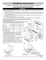
3. Meaoqu-ehetweeninside edges of every other stud as shown
in FIG. 1.
FIG. 1
3-3.,'B"MIN
(8.6 cm)
|
Carefiflly measure and cut artopening with the following
dimeusions depending on yore" model. See FIGS. 1 and 2.
WIDTH "X" = inside model width plus twice the thickness
of flaming material used.
HEIGHT "5?' = inside model height plus twice the thickness
of flaming material used.
Heavy Duty (FAS) Xledian (FAM)
Inside Flmne Height: 187t_"(47,9cm) 18" (45.7cm)
h_side Frame Wide: 26_fd' (67.9cm) 237_" (60.6cm)
Y
FIG. 2
UP TO
8-tt2"
5. Nail flame to spacers to spacers with fforl flushwith
dry_all.
4. Build a wocrden flame with the INSIDE dimensions of
yore- model listed above.(Measure twice remember.,,)
F:ame depth should be the same as wall thickness, Fill in
the s_ace from the opening to the studs with wood spacers,
as shov_a-t.
NOTE:ffwall thicknessis8-1/2"ormore,addalulninum
flashingoverbottomofframeopeningtoassurenowatercan
enterareabetweeninnerandouterwall.
1" LONG
WOOD SCREW
FIG. 2
ALUMINUM FLASHING
OVER BOTTOM OF FRAME
OVER
81/2"
Prepare and Install
Cabinet
Refer to Step 4 of Window Momlting for assembly of support
brackets. A wooden strip nailed to the outside wall should be
used in conjtmction with sill support angle brackets.
1. Slide chassis from cabinet. Refer back to Step 1 of
Window Mounting
2. Place cabinet into opening with bottom rail resting firmly
oll bottom board of wooden frame.
3. Position cabinet to achieve proper slope for water removal.
(See FIG 1 below.)
FIG. 1
5/16"--
TO
318"
LEVEL
314" PLUS
TRIM THICKNESS
SEE PARA 5
e
Wooden strip
5. Screw or nail cabinet wooden frame using shims if frame
is oversized, to eliminate distortion. Remember to maintain
proper slope as described in Step 3.
4. Secure bottom rail to wood frame with two large wood
screws 1"(2.5 cm) long using the two holes in the bottom
of the channel resting on frame. (See FIG. 2 following)
6. Install chassis into cabinet by following all steps in Step
8 of Window Momlting. (continued)
OPTIONAL:Caulkingandinstallationoftrimoninteriorwall
maybedone.Youcanbuywoodfromyourlocallumberor
hardwaresupply.Ontheoutside,caulkopeningsaroundtop
andsidesofcabinet,andallsidesofwoodsleevetotheopening.
NOTE:SeeStep7,Item3ofWindowMountingInstructions
forbottomrailseallocation.
Masonry Construction
1. Cut or build a wall opening in the masonry wall similar
to the frame construction (refer to Step 2 of Thru-the-
Wall Installation for a wall thickness greater than 8-1/
2").
2. Secure cabinet in place using masonry nails, or the right
masoraT anchor screws. (Another w'ay to do this is to build
an in-between t?ame of 2x4's as shown in the Step 2 Prepare
Wall illustrations-but make it double lYamed on either
side, and install between masonry wall opening and cabinet.
Frame must be securely anchored to masonry, wall
opening) This way gives very good louver clearance on
either side of cabinet.
3. install a lintel to support masonry wall above cabinet.
Existing holes in cabinet can be used ands'or additional
holes can be drilled to fasten cabinet at various positions.
Be sure that side louver clearance is in accordance with
Step 1 above.
4. Install exterior cabient support brackets as shown in
Step 2 of Thru-the-Wall Installation. Caulk or flash if
neede, to provide a wether-tight seal around top and
sides of cabinet.
5. To complete installation, apply wood trim molding
around room side projection of cabinet.
  • Page 1 1
  • Page 2 2
  • Page 3 3
  • Page 4 4
  • Page 5 5
  • Page 6 6
  • Page 7 7
  • Page 8 8

Frigidaire FAM18EQ2A1 Installation guide

Type
Installation guide

Ask a question and I''ll find the answer in the document

Finding information in a document is now easier with AI