Page is loading ...

INSTALLATION AND SERVICE MUST BE PERFORMED BY A QUALIFIED INSTALLER.
IMPORTANT: SAVE FOR LOCAL ELECTRICAL INSPECTOR'S USE.
READ AND SAVE THESE INSTRUCTIONS FOR FUTURE REFERENCE.
FOR YOUR SAFETY: Do not store or use gasoline or other flammable vapors and liquids in
the vicinity of this or any other appliance.
IMPORTANT INSTALLATION INFORMATION
•AIi electdc cooktops run off a single phase, three-wire or four-wire cable, 240/208 volt, 60 hertz, AC only
electrical supply with ground.
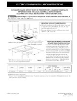
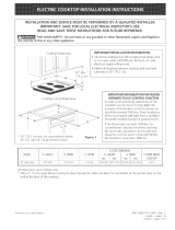
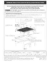
• Minimum distance between cooktop and overhead cabinetry is 30" (76.2 cm).
ForStandard Installation: * 30" (76.2 cm) mh_.for
i unprotected cabinet
24" (61 cm) mh_.for
protected surface
30" Min. *
(76.2 cm)
Cooktop Dh_ensions
Cooktop Cutout Dimensions
C
4"X 8" (10.2 cmx 20.3 cm)
openir g to route armoured cable.
(184(n/)
Do not slide unit into cabinet cutout.
Protruding screws on the bottom of
unit may damage the bottom front
finish.
(89 2 ¢m)
**Note: D & Eare critical to the proper installation
of the cooktop. Pleasemake sureto respectthose
dimensions. D reflects a finished dimension it is
recommended to undercut this dimension and
adjust upon installation of the appliance due to the
Figure 1 variation in countertop materials.
All dimensions are in inches (cm).
Allow 2" (5 cmi space below the armoured cable opening to dear the electric cable and
allow space for installation of the junction box on the wall at the back of the cooktop.
PiN 318201413 (0403) Rev. E
English - pages 15
£spaho - pages 610
Fr._,n_ais pages 1116

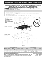
For Installation with the optional Stainless Steel Backsplash. * 30" (76.2 cm) rain. for unprotected cabinet
24" (61 cm)rain, for protected surface
30"(76.2 cm)
Min.*
2"(5.1 cm)
....A B......
9"(22 9cm) Opto_a
Stainless Steel
Backsplash
Cooktop Dimensions
c
• •••• O ••• 4"X8" (10.2cmx20.3cm)
opening to route armoured cable.
2
( / 84 cm)
F
Do not slide unit into cabinet cutout.
Protruding screws on the bottom of unit
may damage the bottom front finish.
Figure 2
dimensions. D reflects afinished dimension it is
recommended to undercut this dimension and
adjust upon installation of the appliance due to the
variation in countertop materials,
All dimensions are in inches (cm),
Allow 2" (5 cm) space below the armoured cable opening to clear the electric cable and
allow space for installation of the junction box on the wall at the back of the cooktop.

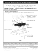
OverheadCabinetShouldNot Exceeda
Maximum Depth of 13" (33 cm)
30" (76.2 cm) Min.
Clearance Between the
Top of the Cooking
Pladorm and the Bottom
of an Unprotected Wood
or Metal Cabinet
24" (61 cm) Min. when
Bottom of Wood or Metal
Cabinet is Protected by
Not LessThan I/8" Flame
Retardant Millboard
Covered With Not Less
Than No. 28 MGS Sheet
Steel, 0.015" (0.4 ram)
Stainless Steel, 0.024"
(0.6 rrirrii_Aluminum or
0.020" (0.5 ram) Copper
10"
,_,tJJt and Nearest (25.4 cm)
Comb _stibleSurface
18' Above Countertop _
_4...7 cm 4
It is riot recommended to use
drawer underneath cooktoD.
25" Min.
cm Min.)
K Min. From Edge of
Cooktop to Nearest
Combustible Wall
(Either Side of Unit).
Fordimensions E, F,G & H, seeTableon oage 1.
ADoroximate Location
of Junction Box
_To eliminate the risk of burns or'fire by
reaching over heated surfaces,cabinet storage spacelocated
abovethe cooktop should be avoided. If cabinet storage is
provided, risk can be reduced by installing a range hood that
projects horizontally a minimum of 7" (17.8 cm) beyond the
bottom of the cabinets.
35" (91.4 cm) 7Y.," (19.1 cm) 1 (2.5 cm)
Figure 3 - COUNTERTOP CUTOUT OPENING
3

Important Notes to the Installer
1. Readall instructions contah_ed in these installation
instructions before installing the cooktop,
2. Remove all packing material before connecting the
electrical supply to the cooktop.
3. Observe all governing codes and ordinances.
4. BesLireto leavethese instructions with the consumer.
Important Note to the Consumer
Keep these instructions with your Use and Care Guide for
future reference,
Depth Adjustment Filler Kit #903051-9010
This cooktop is designed to replace existing unit. If the
depth of your countertop opening is bigger than 7.4" (18.4
cm) and lessthan 8_._"(21.6 cm) you can order a free filler
kit #903051-9010 by calling ServiceCenter at 1-877-
4ELECTROLUX(1-877-435-3287).
Optional Items Available:
* A 9" (22.9cm) Stainless Steel Backsplash
Kit#903048-9010
* A Black Knobs Kit #903049-9010
Those kits can be order through the Service Center at
1-877-4ELECTROLUX(1-877-435-3287). However all cost
related to those kits will be at customer charges.
IMPORTANT SAFETY
INSTRUCTIONS
* Be sure your cooktop is installed and grounded
properly by a qualified installer or service
technician.
* These cooktops must be electrically grounded in
accordance with local codes or, in their absence,
with the National Electrical Code ANSI/NFPA No.
70_latest edition in the United States, or with
CSA Standard C22.1, Canadian Electrical Code, Part
1, in Canada.
_The electrical power to the cooktop
must be shut off while line connections are being
made. Failure to do so could result in serious injury
or death.
Provide Electrical Connection
Install the junction box under the cabinet and run 120I
240 or 120/208 Volt, AC wire from the main circuit
panel. NOTE: DO NOT connect the wire to the circuit
panel at this time. Wait until all wires have been
connected in the junction box.
Electrical Requirements
Observe all governing codes and local ordinances.
1. A 3-wire or 4-wire single phase 1201240 or 120/208
Volt, 60 Hz AC only electrical supply is required on a
separate circuit fused on both sides of the line (time-
delay fuse or circuit breaker is recommended). DO
NOT fuse neutral. The fuse size must not exceed the
circuit rating of the appliance specified on the
nameplate.
NOTE: Wire sizes and connections must conform with
the fuse size and rating of the appliance in accordance
with the National Electrical Code ANSIINFPA No. 70-
latest edition, or with CSA standard C22.1, Canadian
Electrical Code, Part 1, and local local codes and
ordinances.
An extension cord must not be used
with this appliance. Such use may result in a fire,
electrical shock, or other personal injury.
2. The appliance should be connected to the fused
disconnect (or circuit breaker) box through flexible
armored or nonmetallic sheathed cable. The flexible
armored cable extending from this appliance should
be connected directly to the grounded junction box.
The junction box should be located as shown in
Figure 2 with as much slack as possible remaining in
the cable between the box and the appliance, so it
can be moved if servicing is ever necessary.
3. A suitable strain relief must be provided to attach
the flexible armored cable to the junction box.
Unpacking Instructions
1. Unpack and visually inspect the cooktop
2. Besure the bottle of cleaner conditioner packed in the
literature bag is left where the user can find it easily. It
isimportant that the ceramic-glass smoothtop be
pretreated before usesee Cooktop Cleaning and
Maintenance section in the Use and Care Guide.
Electrical Connection
It is the responsibility and obligation of the consumer to
contact a qualified installer to assure that the electrical
installation is adequate and is in conformance with the
National Electrical Code Ai/SIiNFPA Ito. 70-latest
edition, or with CSA Standard C22.1, Canadian
Electrical Code, Part 1, and local codes and ordinances.
Electrical ground is required on this appliance.
This appliance isequipped with a copper conductor
flexible cable. If connection is made to aluminum house
wiring, use only special connectors which are approved
for joining copper and aluminum wires in accordance
with National Electrical Code and local codes and
ordinances.
This appliance is manufactured with a white neutral
power supply wire and a frame connected green or bare
copper grounding wire.

1. If local codes permit connection of the frame
grounding conductor to the neutral (white) wire.
Connect the green (or bare copper) wire and the
white wire from the appliance cable to the supply
cable ground wire (white or bare) inside the junction
box. Connect the remaining wires inside the junction
box from the power supply cable to the matching
colors of the appliance cable wires (figure 4).
Cablefror_Po_+,erSuppf',,'
Junction Box
"White Wre
GroundWire / UL Luted Conduit
[Bate,o+G+eenWde) / Connectoro+CSAlisted)
Cablefrom appliance
Figure 4
3-WIRE GROUNDED JUNCTION BOX
_lmproper connection of aluminum
house wiring to copper leads can result in a short
circuit or fire. Use only connectors designed for
joining copper to aluminum, and follow the
manufacturer's recommended procedure closely.
Frame grounded through the neutral.
If used in a mobile home, new branch circuit (1996
NEC) recreational vehicles or where local codes do
not permit grounding through neutral see figure 5.
2. If used in mobile homes or if local codes DO
NOT permit connection of the frame grounding
conductor to the neutral (white) wire, separate
the white and bare copper ground wires that extend
out of the end of the supply cable of the appliance.
Connect the white wire from supply cable to the
neutral white wire in the junction box. Connect the
black and red wires from the supply cable to the
matching color wires in the junction box. The bare
wire must now be used to ground the appliance in
accordance with local electrical codes. Connect the
bare copper ground wire to the grounded lead in the
service panel. DO NOT ground to a gas supply pipe.
DO NOT connect to electrical power supply until
appliance is permanently grounded. Connect the
ground wire before turning on the power (figure 5).
_lf connecting to a 4-wire electrical
system, the appliance frame MUST NOT be
connected to the neutral wire of the 4-wire
electrical system.
Cube from Power Su#ply
Grousd Wire \
Red
Wi_es
• ,, White Wire
G_ound Wire
Bare or GreenWre} ....
Black
Wi;es
i
1unctionBox ......... UL Luted Conduit
Connector(o: CSAlisted)
Cablefrom appliance
Figure 5
4-WIRE GROUNDED JUNCTION BOX
NOTE TO ELECTRICIAN: The armored cable leads
supplied with the appliance are CSA-recognized for
connection to larger gauge household wiring. The
insulation of the leads is rated at temperatures much
higher than temperature rating of household wiring. The
current carrying capacity of the conductor is governed by
the temperature rating of the insulation around the wire,
rather than the wire gauge alone.
Cooktop Installation
1. Visually inspect the cooktop for damage.
2. If you are installing the optional Stainless Steel
backsplash, first fix it at the back of the cooktop using
the screws supplied with the Kit and follow the
instructions attached.
Go to step 3, If you are not installing the Optional
Stainless Steel backsplash.
3. Set the cooktop into the countertop cutout.
NOTE: Do not use caulking compound; cooktop should
be removable for service when needed.
Checking Operation
Refer to the Use and Care Guide for operation.
Do not touch cooktop glass or elements.
They may be hot enough to burn.
Model and Serial Number Location
Theserialplate islocated under the cooktop or inthe burner
boxand can be seenby lifting up the main top of unit.
When ordering parts for or making inqukes about your
cooktop, always be sure to include the nqodel and serial
numbers and a lot number or letter from the serial plate
on your cooktop.
Before You Call for Service
Read the Before You Call for Service Checklist and
operating instructions in your Use and Care Guide. It
may save you time and expense. The list includes
common occurrences that are not the result of defective
workmanship or materials in this appliance.
Refer to your Use and Care Guide for Searsservice
phone numbers. Please call if you have inquiries about
your product and/or need to order parts.
5
/