Page is loading ...

Passionate about Music
w w w . B e t t e r M u s i c B u i l d e r . c o m
Thank you for purchasing this unit. To
make full and effective use of this unit,
please read this Owner's Manual
carefully before operating it. Please
retain this manual for future reference.
UHF
Frequency Selectable
2-in-1 Base Module
***
1 Receive Module with 2 Wireless Microphones System
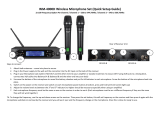
Professional UHF Wireless Microphone System
VM-93C G5
Operating Instructions
Better Music Builder .com
®
Passionate about Music
It’s what we do!
Rechargeable with Lithium-ion Battery
SQ L
POWER
RF AF
MHZ
VOL
SQL
AF RF
MHZ
VOL
SQL
M
SQ LSQ L
SE TSE T
MODULEMODULE
VM-93C G5
CHR
SET
MENU
UHF WIRELESS SYSTEM VM-93C G5
MHz
MHz
BATTERY LIFE
CHR
SET
MENU
UHF WIRELESS SYSTEM VM-93C G5
MHz
MHz
BATTERY LIFE

CONTENTS
INTRODUCTION................................................................................ 1
SYSTEM FEATURES............................................................................. 1
PACKAGE ACCESSORIES................................................................... 2
2-in-1 BASE MODULE.................................................................... 3~4
• Controls and Functions................................................................. 3~4
HARDWARE SETUP........................................................................ 5~7
HANDHELD MICROPHONE........................................................... 8~9
• Controls and Functions................................................................ 8~10
OPERATION............................................................................... 11~19
• Selecting Receiver Frequency......................................................... 11
• Lock/Unlock Receiver Setting......................................................... 11
• Scanning Receiver Frequency ....................................................... 12
• Selecting Frequencies with Module Groups................................ 13
• Charger Base Menu Diagram........................................................ 14
• Selecting Frequency with Charger Base....................................... 15
• Adjusting Sensitivity with Charger Base....................................... 16
• Selecting Intelligent Energy Control.............................................. 17
• Start/Cancel Charging Microphone............................................. 18
• Lock/Unlock Charger Base Setting............................................... 19
TECHNICAL SPECIFICATIONS.......................................................... 20
BODY-PACK MICROPHONE (Optional)...................................... 21~22
TROUBLESHOOTING.................................................................. 23~24
APPENDIX................................................................................. 25~26
WARRANTY..................................................................................... 27
CONTACT INFORMATION............................................................... 28
Base Module
Features
Package
Intro
Handheld
Contact Us
Specs
Appendix
Warranty
Troubleshooting
Body-Pack
Operation
Set Up

1
INTRODUCTION
The Better Music Builder VM-93C G5 is a Fifth Generation UHF Dual-Channel
Microphone System that uses the latest technologies and engineering. Its heavy
duty design features two handheld microphones with one 2-in-1 Base Module,
Intelligent Energy Control, and innovative Charger Bases.
The Wireless Microphones are equipped with six-axis gyroscope sensor to be
the most intelligent and energy efficient microphones. Utilizing the sensor, the
Intelligent Energy Control feature integrated onto the microphones has the ability
to automatically enter Auto-Mute Mode, Sleep Mode and Auto-Shutdown
when left unattended, greatly increasing the overall battery life.
The VM-93C G5 offers many convenient features. It features 10 preset
Frequency Module Groups and Automatic Frequencies Scan to allow for easy
frequency configuration. Both the receiver and microphones feature Lock Mode
to safe guard your favorite settings.
Equipped with lithium-ion rechargeable batteries, the VM-93C G5 wireless
microphones have a 10 hours battery life. It features two innovative Charger
Bases with LCD Display.
Better Music Builder is simply the best solution for home and professional
karaoke performance!
SYSTEM FEATURES
• Six-axis gyroscope sensor integrated onto each microphone.
• Intelligent Energy Control.
• UHF Dual-Channel in a 2-in-1 Base Module.
• Utilizing the latest wireless technologies and engineering.
• Clear LCD Screen displays Radio Frequency, Audio Frequency, Frequency,
Module Group, Battery, Volume, Mute and Squelch.
• Clear Voice Technology delivers crystal clear sound.
• 100 Selectable Channels.
• 10 Preset Frequency Module Groups.
• Automatic Frequencies Scan.
• Lock Mode.
• Squelch Control.
• 10 hours of battery life with lithium-ion rechargeable battery.
• Innovative Charger Bases with LCD Display.
• Adjustable antennas for better signal receiving.
• Rack Mountable.
Features
Intro

PACKAGE ACCESSORIES
The package comes with (1) 2-in-1 Base Module [Receiver], (2) receiver
antennas, (2) handheld microphones, (2) handheld microphone charger bases,
(3) DC power adapters, and (1) audio cable.
Package
2
2-IN-1 BASE MODULE [RECEIVER]: 1 UNIT
RECEIVER ANTENNA: 2 UNITS
7 in
17.5 cm
HANDHELD MICROPHONE CHARGER BASE: 2 UNITS
HANDHELD MICROPHONE: 2 UNITS
AUDIO CABLE
(FOR MIXED OUTPUT): 1 UNIT
For better connection, XLR to
XLR cable is recommended.
Recomme nd
DC POWER ADAPTER: 3 UNITS
DC-POWER USAGE: This
wireless microphone system is designed
specifically for North America that uses
120V for DC power. For usage in Asia
or Europe, please change it to 220V.
NOTE
CHR
MENU
SET
MHz
BATTERY LIFE
CHR
MENU
SET
MHz
BATTERY LIFE
SE T
SQ L
SE T
SQ L
RF AF
MHZ
VOL
SQL
AF RF
MHZ
VOL
SQL
M
POWER
MODULEMODULE
VM-93C G5
UHF WIRELESS SYSTEM VM-93C G5
MHz
UHF WIRELESS SYSTEM VM-93C G5
MHz

SE T
SQL
SE T
SQL
POWER
RF AF
MHZ
VOL
SQL
AF RF
MHZ
VOL
SQL
M
MODULEMODULE
VM-93C G5
Base Module
3
2-in-1 BASE MODULE [RECEIVER]
CONTROLS AND FUNCTIONS
FRONT PANEL:
1. DOWN BUTTON: Adjusts frequency in “SET FRQ” and “SCAN” mode.
2. SET BUTTON: Mode selector: “SET FRQ > SCAN > EXIT”.
3. UP/LOCK BUTTON: Adjusts frequency in “SET FRQ” and “SCAN” mode.
The “UP” button also acts as a “LOCK/UNLOCK” button.
4. MODULE BUTTONS: Selection of 10 preset groups.
5. LCD DISPLAY: Displays system status.
6. SQL BUTTON: Selects squelch level.
7. POWER BUTTON: Turns the system on/off.
8. VOLUME CONTROL: Controls microphone volume.
1 2 3 7654 8
The “DOWN” button would be in no use when lock mode is on ("LOCK" will appear
on the LCD).
NOTE

4
MI C 2 X L R B A L ANC E D
AUDIO OUTPU T
TRUE
DIVERSIT Y
MIX
MIC 1 & 2
UNBAL AN CED
COOLIN G V ENT
MI C 1 X L R B A L ANC E D
AUDIO OUTPU T
ANT ENN A -AANT ENN A - B
RISK OF ELEC TRIC SHOCK
DO NOT OPEN
397170516300
Better Music Builder
Mode l No.: VM-93C G5
CALIFORNIA, UNITED STATES OF AMERIC A
w w w. Be tt e r Mu si cB u il de r . c om
ENGINEERED AND DESIGNED IN U.S.A.
LCD PANEL:
After turning on the “POWER”, LCD screen will display the following:
9. BATTERY STATUS: Indicates battery life on the microphone.
10. MUTE: Indicates if microphone is powered off.
11. VOLUME: Indicates when adjusting microphone volume.
12. RADIO FREQUENCY LEVEL: Strength indicator of radio signal.
13. AUDIO FREQUENCY LEVEL: Strength indicator of incoming audio signal.
14. SQUELCH: Indicates when adjusting squelch level.
15. FREQUENCY: Displays current frequency.
REAR PANEL:
16. COOLING VENT
17. ANTENNA-B: Connect the antenna to the BNC socket.
18. MIC 2 BALANCED OUTPUT: Balanced XLR audio output.
19. POWER SUPPLY: For power adapter with DC 8V 1.7A.
20. MIXED OUTPUT: Unbalanced 1/4" audio output for MIC 1 & MIC 2.
21. MIC 1 BALANCED OUTPUT: Balanced XLR audio output.
22. ANTENNA-A: Connect the antenna to the BNC socket.
RF AF
MHZ
VOL
SQL
AF RF
MHZ
VOL
SQL
M
9 10 11
12 13 14 15
1716 2218 2120
DC-POWER
DC 8V
1.7A
19

MI C 2 X L R B A L ANC E D
AUDIO OUTPU T
TRUE
DIVERSIT Y
MIX
MIC 1 & 2
UNBAL AN CED
COOLIN G V ENT
MI C 1 X L R B A L ANC E D
AUDIO OUTPU T
ANT ENN A -AANT ENN A - B
RISK OF ELEC TRIC SHOCK
DO NOT OPEN
397170516300
Better Music Builder
Mode l No.: VM-93C G5
CALIFORNIA, UNITED STATES OF AMERIC A
w w w. Be tt e r Mu si cB u il de r . c om
ENGINEERED AND DESIGNED IN U.S.A.
DC-POWER
DC 8V
1.7A
5
Set Up
HARDWARE SETUP
AUDIO OUTPUT CONNECTION:
There are three rear audio outputs as shown in the below diagram:
1. Mic 2 Balanced Output
Mic 2 Balanced Output is balanced audio output for MIC 2 using XLR
connection. MIC 2 effects can be controlled without affecting MIC 1 effects.
2. Mic 1 Balanced Output
Mic 1 Balanced Output is balanced audio output for MIC 1 using XLR
connection. MIC 1 effects can be controlled without affecting MIC 2 effects.
3. Mic 1 & 2 unbalanced Output
Unbalanced audio output for MIC 1 & MIC 2 using 1/4” connection. MIC 1
and MIC 2 shares a single signal. To produce different effects on two
microphones, MIC 1 and MIC 2 need independent signals using separate XLR
connections.
3
MIXED OUTPUT
(MIC 1 & 2 UNBALANCED)
MIC 1 BALANCED OUTPUT
(BALANCED XLR)
2
MIC 2 BALANCED OUTPUT
(BALANCED XLR)
1
We recommend using balanced XLR connections if the distance between the
microphone receiver and the mixer is more than 10 feet. The grounding of the
balanced XLR connection delivers better quality signal by reducing noise.
Recommend

MI C 2 X L R B A L ANC E D
AUDIO OUTPU T
TRUE
DIVERSIT Y
MIX
MIC 1 & 2
UNBAL AN CED
COOLIN G V ENT
MI C 1 X L R B A L ANC E D
AUDIO OUTPU T
ANT ENN A -AANT ENN A - B
RISK OF ELEC TRIC SHOCK
DO NOT OPEN
397170516300
Better Music Builder
Mode l No.: VM-93C G5
CALIFORNIA, UNITED STATES OF AMERIC A
w w w. Be tt e r Mu si cB u il de r . c om
ENGINEERED AND DESIGNED IN U.S.A.
DC-POWER
DC 8V
1.7A
6
XLR
Balanced Input
XLR
Balanced Input
XLR
Balanced Input
XLR
Balanced Input
1/4"
Unbalanced Input
1/4"
Unbalanced Input
1/4"
Unbalanced Input
1/4"
Unbalanced Input
UHF WIRELESS SYSTEM DIAGRAM:
BALANCED CONNECTION
MIXER AMPLIFIER OR KARAOKE UNIT INPUT TERMINAL
REAR VIEW
MIC 2 HANDHELD MICROPHONEMIC 1 HANDHELD MICROPHONE
CONNECTING POWER ADAPTER:
For North America, use 120V, DC 8V 1.7A power adapter. For Asia or
Europe, use 220V~ 240V DC power adapter with a maximum battery
capacity of 1.7A.
NOTE
Please make sure to use the correct DC power adaptor. Otherwise, it may damage the
2-in-1 Base Module and/or the charger because their maximum battery capacity is different. The
warranty will be voided if product is damaged using the wrong DC power adapter.
REAR VIEW
UHF WIRELESS SYSTEM VM-93C G5
MHz
UHF WIRELESS SYSTEM VM-93C G5
MHz

7
OPTIONAL 19” RACK MOUNT KIT:
To put the system onto one of the mount kits, please follow the diagram below.
Single Receiver Rack Mount Kit
Dual Receiver Rack Mount Kit
10 inches
19 inches
16.6 inches
Rack mount kit is not included in package.
ANTENNA IS
ADJUSTABLE
10 inches
19 inches
8.3 inches 5.4 inches5.4 inches
Rack mount kit is not included in package.
ANTENNA IS
ADJUSTABLE
SQ L
POWER
RF A F
MHZ
VOL
SQL
AF R F
MHZ
VOL
SQL
M
SQ LSQ L
SE TSE T
MODULEMODULE
VM-93C G5
SQ L
VM-93C G5
POWER
RF A F
MHZ
VOL
SQL
AF R F
MHZ
VOL
SQL
M
SQ LSQ L
SE TSE T
SQ L
VM-93C G5
POWER
RF A F
MHZ
VOL
SQL
AF R F
MHZ
VOL
SQL
M
SQ LSQ L
SE TSE T

UHF WIRELESS SYSTEM VM-93C G5
MHz
8
Handheld
HANDHELD MICROPHONE
CONTROLS AND FUNCTIONS
1. INTERCHANGEABLE MICROPHONE HEAD
2. LCD DISPLAY: Displays frequency and battery status.
3. POWER BUTTON
4. LITHIUM-ION BATTERY: Battery Capacity 1600mAh.
5. CHARGER CONNECTION
LCD PANEL:
After turning on the power, the LCD screen will display the following:
BATTERY STATUS:
Full Battery:
Indicates full battery
on the microphone.
A full battery lasts up
to 10 hours.
1
5
32 4
LCD screen blinks when
battery is extremely low.
Low Battery:
Indicates low battery on
the microphone. When
the LCD screen is blinking,
it’s time to recharge the
microphone.
NOTE
Batteries are not covered under our product warranty.
6. BATTERY STATUS: Indicates battery life.
7. IEC ON/OFF: Indicates if Intelligent Energy
Control is on or off.
8. FREQUENCY: Displays current frequency.
MHz
MHz MHz
MHz
6
8
7

9
HIGH TECH INTELLIGENT ENERGY CONTROL (IEC) FEATURES
This function’s primary focus is energy saving. To do so, the microphones are
equipped with six-axis gyroscope sensor.
FEATURES:
1. Energy Saving
AUTO-MUTE MODE:
The six-axis gyroscope senses speed in three directions as well as any
angular changes in velocity. This information is transmitted through the sensor
and minimizes power consumption by entering “auto-mute mode” when it
senses no movement within 3 seconds.
SLEEP MODE:
If microphone continues to remain idle in “auto-mute mode” for 5 minutes,
it will go to “sleep mode”. The Intelligent Energy Control will turn off the
radio signal in order to achieve energy saving.
AUTO SHUTDOWN:
If microphone continues to remain idle in “sleep mode” for 3 minutes, it
will be automatically shutdown.
2. Auto-Mute When Not Held
The microphone detects and auto-mutes when it stays idle for 3
seconds. This function can avoid most unwanted noise and greatly decrease
the chances of any damage to the audio equipment. The microphone will
operate normally again once motion is detected.
3. Instant “Wake up” Response
The microphone can switch from “sleep mode” to operating mode in
milliseconds with its intelligent sensory technology.
AUTO-MUTE MODE
MHz

CHR
MENU
SET
MHz
BATTERY LIFE
MHz
BATTERY LIFE
CHARGING
10
CHARGER BASE:
1. MICROPHONE DOCK
2. SET BUTTON: Confirms selection.
3. UP/DOWN BUTTONS: Adjusts selection.
4. LOCK: Locks all operations except charging function.
5. CHARGE BUTTON
6. LCD DISPLAY: Displays frequency, battery and charging status.
7. MENU BUTTON: Enters frequency, sensitivity, and intelligent energy
control mode.
8. UP/DOWN BUTTONS: Selects frequency, sensitivity, and intelligent
energy control mode.
9. POWER SWITCH
10. MOUNTING-SCREW HOLES
11. POWER SUPPLY: For North America, DC 8V 1.7A power adapter.
For Asia or Europe, use 220V~ 240V DC power adapter with a
maximum battery capacity of 1.7A.
LCD PANEL:
After turning on the power, the LCD screen will display the following:
FRONT VIEW
REAR VIEW
7 106 95 114
3 81
2
14
15
12
13
12. BATTERY STATUS: Indicates battery life.
13. BATTERY LIFE PERCENTAGE
14. BATTERY LIFE / CHARGING: Indicates if
battery is charging or not.
15. FREQUENCY: Current value depends on setting.

11
Operation
OPERATION
LOCK/UNLOCK RECEIVER SETTING
Press and hold “UP ▲” on the receiver to lock/unlock the setting.
SELECTING RECEIVER FREQUENCY
STEP 1: Press and hold “SET” until “SET FRQ” displays.
STEP 2: While “MHZ” icon is blinking, press “UP ▲” or “DOWN ▼” to select
frequency.
STEP 3: Once frequency is selected, press “SET” to confirm (”STORE” will
appear on the LCD). The “MUTE” icon will be replaced with microphone battery
icon, and RADIO FREQUENCY bars.
SET
SQL
AF RF
MHZ
M
POWER
MODULE
NOTE
The “UP/SET/DOWN” buttons would be in no use when lock mode is on ("LOCK" will
appear on the LCD). Press and hold “UP ▲” button to unlock (“UNL OCK” will appear on the LCD).
SET
SQL
AF RF
MHZ
M
POWER
MODULE
SET
SQL
AF RF
MHZ
M
POWER
MODULE
SE T
SQL
AF RF
MHZ
M
POWER
MODULE
SE T
SQL
AF RF
MHZ
M
POWER
MODULE
SE T
SQL
AF RF
MHZ
M
POWER
MODULE
SE T
SQL
AF RF
MHZ
M
POWER
MODULE
SE T
SQL
AF RF
MHZ
M
POWER
MODULE

VM-93C G5
SE T
SQ L
SE T
SQ L
RF AF
MHZ
VOL
SQL
AF RF
MHZ
VOL
SQL
M
POWER
MODULEMODULE
12
SCANNING RECEIVER FREQUENCY WITH MICROPHONE
STEP 1: Turn ON the receiver and microphone, point the microphone directly at
the receiver.
STEP 2: Press and hold “SET” and then press “SET” again until “SCAN” displays.
STEP 3: While “MHZ” icon is blinking, press “UP ▲” or “DOWN ▼” to scan
frequency.
STEP 4: Once scanning is completed, press “SET” to confirm (”STORE” will
appear on the LCD). The “MUTE” icon will be replaced with microphone battery
icon, and RADIO FREQUENCY bars.
Please make sure that the other
handheld microphone is powered off when
adjusting the frequency on one microphone.
Each unit is fully tested and qualified by the
manufacturer. However, due to the nature of
wireless connection, interference may occur
because of local environments and/or radio
signals emitted by other wireless devices
within the household.
NOTE
Maximum Range 10 feet
S
C
ANN
I
NG
P
R
O
C
E
S
S
NOTE
The “UP/SET/DOWN” buttons would be in no use when lock mode is on ("LOCK" will
appear on the LCD). Press and hold “UP ▲” button to unlock (“UNL OCK” will appear on the LCD).
SE T
SQL
AF RF
MHZ
M
POWER
MODULE
SCANNING
PROCESS
SE T
SQL
AF RF
MHZ
M
POWER
MODULE
SET
SQL
AF RF
MHZ
M
POWER
MODULE
SET
SQL
AF RF
MHZ
M
POWER
MODULE
SET
SQL
AF RF
MHZ
M
POWER
MODULE
SET
SQL
AF RF
MHZ
M
POWER
MODULE
MHz
UHF WIRELESS SYSTEM VM-93C G5

SE T
SQL
SE T
SQL
RF AF
MHZ
AF RF
MHZ
M
POWER
MODULEMODULE
VM-93C G5
VM-93C G5
SE T
SQL
SE T
SQL
RF AF
MHZ
AF RF
SQL
M
POWER
MODULEMODULE
VM-93C G5
MODULEMODULE
SE T
SQL
SE T
SQL
RF AF
MHZ
AF RF
VOL
M
POWER
13
SELECTING FREQUENCIES WITH MODULE GROUPS
The receiver has 10 preset frequency module groups. Press the yellow “+” or “–”
button to select module groups.
SELECTING SQUELCH LEVEL
Press “SQL” button to select the squelch level.
ADJUSTING MICROPHONE VOLUME
Press the black “+” or “–” button to adjust the microphone volume.
NOTE
The “UP/SET/DOWN” buttons would be in no use when lock mode is on ("LOCK" will
appear on the LCD). Press and hold “UP ▲” button to unlock (“UNL OCK” will appear on the LCD).
We recommend setting the microphone volume to a medium level,
then control the overall volume on the amplifier/mixer.
Recommend

14
CHARGER BASE MENU DIAGRAM
MENU
SET
SET SEN
SET
00 dB –30 dB
STORE
SET SEN
SET
SET FRQ
SET
926.000MHz 936.000MHz
STORE
SET FRQ
SET
SET IEC
SET
ON OFF
STORE
SET IEC
EXIT
MENU
Before entering “MENU”, make sure it is not
charging. Press “CHR” button to cancel charging.
NOTE
CHR
MENU
SET
MHz
BATTERY LIFE
FRQ: Frequency
SEN: Sensitivity
IEC: Intelligent Energy Control
: Button
: LCD Screen

SE T
MHz
BATTERY LIFE
SELECTING FREQUENCY WITH CHARGER BASE
Before entering “MENU”, make sure it is not charging. Press “CHR” button to
cancel charging.
STEP 1: Place microphone in the charges base. Then turn on the microphone
and charger base.
STEP 2: Press and hold “MENU” until “SET FRQ” displays. Then press “SET” until
frequency displays and “MHz” is blinking (Microphone’s LCD display lights up
and “MHz” is blinking).
STEP 3: While “MHz” is blinking, press “UP ▲” or “DOWN ▼” to select
frequency (Microphone’s LCD display changes at the same time).
STEP 4: Once frequency is selected, press “SET” to confirm (”STORE” will
appear on the LCD).
STEP 5: Press “MENU” until “EXIT” displays.
15
SE T
SE T
SE T
MENU
MHz
BATTERY LIFE
MHz
BATTERY LIFE
MHz
BATTERY LIFE
MENU
SE T
MENU
MHz
BATTERY LIFE
MHz
BATTERY LIFE
MHz
BATTERY LIFE
SE T
MHz
BATTERY LIFE
SE T
MHz
BATTERY LIFE
MENU
MHz
BATTERY LIFE BATTERY LIFE

SE T
16
ADJUSTING SENSITIVITY WITH CHARGER BASE
Before entering “MENU”, make sure it is not charging. Press “CHR” button to
cancel charging.
STEP 1: Place microphone in the charges base. Then turn on the microphone
and charger base.
STEP 2: Press and hold “MENU” until “SET FRQ” displays. Then press “UP ▲”
until “SET SEN” displays.
STEP 3: Press “SET” until senstivity (00dB~-30dB) displays. Press “UP ▲” or
“DOWN ▼” to select senstivity (Microphone’s LCD display changes at the
same time).
STEP 4: Once senstivity is selected, press “SET” to confirm (”STORE” will appear
on the LCD).
STEP 5: Press “MENU” until “EXIT” displays.
MENU
BATTERY LIFE
SE T
BATTERY LIFE
SE T
BATTERY LIFE
SE T
MHz
BATTERY LIFE
MENU
MHz
BATTERY LIFE
MENU
BATTERY LIFE
BATTERY LIFE
SE T
BATTERY LIFE
SE T
BATTERY LIFE
MENU
BATTERY LIFE
MENU
BATTERY LIFE

BATTERY LIFE
SE T
BATTERY LIFE
SE T
BATTERY LIFE
SE T
BATTERY LIFE
17
Before entering “MENU”, make sure it is not charging. Press “CHR” button to
cancel charging.
STEP 1: Place microphone in the charges base. Then turn on the microphone
and charger base.
STEP 2: Press and hold “MENU” until “SET FRQ” displays. Then press “DOWN
▼” until “SET IEC” displays.
STEP 3: Press “SET” until “IEC ON” or “IEC OFF” displays. Press “UP ▲” or
“DOWN ▼” to select “ON” or “OFF” (Microphone’s LCD display changes at
the same time).
STEP 4: Once “IEC ON” or “IEC OFF” is selected, press “SET” to confirm
(”STORE” will appear on the LCD).
STEP 5: Press “MENU” until “EXIT” displays.
SELECTING INTELLIGENT ENERGY CONTROL WITH CHARGER BASE
MENU
SE T
MENU
BATTERY LIFE
MENU
BATTERY LIFE
SE T
BATTERY LIFE
BATTERY LIFE
MHz
BATTERY LIFE
MENU
MHz
BATTERY LIFE
MENU
SE T
BATTERY LIFE

CHR
MENU
SET
MHz
BATTERY LIFE
18
CHARGING MICROPHONE
STEP 1: Make sure microphone is off. Then
place microphone in the charger base.
STEP 2: Turn on the charger base.
STEP 3: Press “ ” button “SCAN” will
display and then “CHARGING” will start
blinking until it is fully charged.
UHF WIRELESS SYSTEM VM-93C G5
1
2
3
POWER OFF
NOTE
Turn off charger base or cancel charging
before removing microphone to avoid damage to
microphone and charger base.
CHR
CANCEL CHARGING MICROPHONE
Press “ ” button on the charger base to cancel charging.
CHR
CHR
CHR
MHz
BATTERY LIFE
CHR
MHz
CHARGING
MHz
CHARGING
CHR
MHz
BATTERY LIFE
CANCEL
CHARGING
START
CHARGING
/