Page is loading ...

Mounting Instructions
Öhlins shock absorber kit
BM 346, 347 & EC Unit for BMW K 1200 RS
© Öhlins Racing AB. All rights reserved. Any reprinting or unauthorized use without the
written permission of Öhlins Racing AB is prohibited. Printed in Sweden.
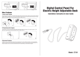
Öhlins shock absorber
Your Öhlins shock absorber type 36 HRC3L/
46 HRC3L features the following adjusters:
Compression damping adjuster
Adjustments are made by setting the electronic
adjustment device. The higher the number is, the
higher the compression damping will be.
Rebound damping adjuster
Adjuster wheel on the piston shaft above the end
bracket.
Spring pre-load adjuster
Adjustments are made by turning the threaded
ring on the shock absorber body. Use the tool
provided. Clockwise for harder adjustment,
counter clockwise to release the pre-load.
Length adjuster
Adjustment is made by turning the end eye and
tightening with the lock nut.
NOTE!
When delivered the Öhlins shock absorber is
dialed to recommended settings for the specific
brand and make of the motorcycle. If you have
changed the settings, check like this:
The adjusters have a normal right hand thread. Turn
the damping adjusters clockwise to fully closed (pos.
zero [0]). Turn counter clockwise to open and count
the clicks until you reach the recommended number
of clicks. See Setup data at last page.
CAUTION!
Do not use too much force, delicate sealing sur-
faces can be damaged.
1. Compression damping adjuster
2. Rebound damping adjuster
3. Spring pre-load adjuster
4. Length adjuster
1
3
2 4
Öhlins Racing AB, Box 722, S-194 27 Upplands Väsby, Sweden.
Phone +46 8 590 025 00. Fax +46 8 590 025 80.
www.ohlins.com
Part No. BM 346, 347 & EC Unit. Issued 05 03 02
Setup data
BM 346
Shock absorber length
(model 2003 and earlier) 321 (+5/-5) mm
(model 2004 and later) 326 (-10/+0) mm
Shock absorber stroke 81 mm
Spring pre-load 7 mm
Rebound damping adjuster 12 clicks
Compression damping adj. var.
BM 347
Shock absorber length 355 (+12/-0) mm
Shock absorber stroke 57 mm
Spring pre-load 20 mm
Rebound damping adjuster 18 clicks
Compression damping adj. var.
Checking sag and ride height
Front suspension
F1. Bike on a stand with the
suspension fully extended = ............
F2. Bike on the ground without rider = ............
F3. Bike on the ground with rider = ............
Free sag
F1 - F2 = ............
Ride height
F1 - F3 = ............
Rear suspension
R1.Bike on a stand with the
suspension fully extended = ............
R2.Bike on the ground without rider = ........... .
R3.Bike on the ground with rider = ............
Free sag
R1 - R2 = ............
Ride height
R1 - R3 = ............
WARNING!
If the shock absorber has an ad-
justable end eye/bracket, this
must not be threaded out more
than that one groove is fully vis-
ible beneath the lock nut. Make
sure that the lock nut is tight-
ened after adjustment.
Groove
Bike on a stand.
F1
R1
Bike on the ground.
F2
R2
Bike with rider on.
F3
R3

Before installation
Öhlins Racing AB can not be held responsible for
any damage whatsoever to shock absorber or
vehicle, or injury to persons, if the instructions for
fitting and maintenance are not followed exactly.
Similarly, the warranty will become null and void
if the instructions are not adhered to.
WARNING!
1. Installing a shock absorber, that is not
approved by the vehicle manufacturer, may
affect the stability of your vehicle. Öhlins
Racing AB cannot be held responsible for
any personal injury or damage whatsoever
that may occur after fitting the shock
absorber. Contact an Öhlins dealer or other
qualified person for advice.
2. Please study and make certain that you
fully understand all the mounting instructions
and the owners manuals before handling this
shock absorber kit. If you have any questions
regarding proper installation procedures,
contact an Öhlins dealer or other qualified
person.
3. The vehicle service manual must be referred
to when installing the Öhlins shock absorber
Safety signals
Important information concerning safety is
distinguished in this manual by the
following notations:
The Safety alert symbol means:
Caution! Your safety is involved.
WARNING!
Failure to follow warning instructions
could result in severe or fatal injury
to anyone working with, inspecting or
using the suspension, or to bystanders.
CAUTION!
Caution indicates that special pre-
cautions must be taken to avoid dam-
age to the suspension.
NOTE!
This indicates information that is of
importance with regard to procedures.
Öhlins products are subject to continual improve-
ment and development. Consequently, although
these instructions include the most up-to-date
information available at the time of printing, there
may be minor differences between your suspen-
sion and this manual. Please consult your Öhlins
dealer if you have any questions with regard to
the contents of the manual.
NOTE!
During storage and transportation, especially
at high ambient temperature, the oil and
grease used for assembling may run out
inside the packing and damage the expanded
polystyrene packing material. This is not
unusual and is in no way detrimental to the
shock absorber.
Kit contents
Before installing the shock absorber, please
check the contents of the kit. If anything is
missing, contact your Öhlins dealer.
BM 346
Description Pcs. Part No.
Shock absorber 36 HRC3L 1 BM 346
Hose clamp stainless 2 00643-02
Rubber mount reservoir 2 00230-01
Tie-rap 6 00231-01
C-spanner 1 00710-01
Sticker Öhlins 2 00192-01
Owners manual 1
BM 347
Description Pcs. Part No.
Shock absorber 46 HRC3L 1 BM 347
Control Unit w. scotch lock 1 03700-01
Spacer 2 01138-01
Hose clamp stainless 1 00643-03
Bracket 1 03720-01
Bracket, reservoir 1 03721-01
Tie-rap 12 00231-01
C-spanner 1 00710-02
Screw M3x6 3 00382-20
Sticker Öhlins 2 00192-01
Owners manual 1
NOTE!
The control unit will automatically switch to the
correct mode: single suspension or front and rear
suspension.
Functions for front and rear suspension:
A Press for front suspension
B Press for rear suspension
C Press for front and rear
After C the function returns to A.
NOTE!
If the button is pressed for at least one second
the display will show the voltage for five seconds.
Functions for single suspension only:
A Press for voltage readings
B Press to turn the voltage readings off
After B the function returns to A
WARNING!
Do not alter the damping when riding in traffic.
The motorcycle must come to a stop before the
damping is set. To avoid dangerous situations,
do not take your eyes and attention off the traffic
and your surroundings.
When the motorcycle is restarted the adjusters will
return to the earlier choosen positions. If the power
supply fails there is always a certain damping force
in the shock absorber, to contribute to safe riding.
Troubleshooting
Er1 No power to the front damper
Measures: Make sure the damper is
connected. Check cables and
connections for damages.
Er2 No power to the rear damper
Measures: Make sure the damper is
connected. Check cables and
connections for damages.
Er3 No power to front and rear dampers
Measures: Make sure the dampers are
connected. Check cables and
connections for damages.
Er4-Er7 Insufficient voltage to the control unit
Measures: Check battery and alterna-
tor. Check all connections.
NOTE!
If you have two dampers connected to the control
unit and one of them suffers a cable failure while the
power is off, the control unit will automatically switch
to single damper mode next time it is powered on.
Er1 and Er2 will only show up if the connection fails
during power on.

WARNING!
1. It’s advisable to have an Öhlins dealer or other
qualified person to fit your shock absorber.
2. Instructions in the vehicle service manual are
to be followed when changing the shock
absorber.
3. When working on a lifted vehicle it must be
securely supported to prevent it from falling.
Mounting Instructions
Öhlins front shock absorber BM 346.
36 HRC3L
1
Put the motorcycle on a stand so the front wheel
is clear of the ground. Make sure it’s steadily fixed
so it will not fall over.
NOTE!
The front wheel must have a distance of 100 mm
from the ground.
7
Use the original mounting rubbers, washer and
nut to first fit the upper bracket.
8
Fit the lower bracket. Use the original bolt and nut.
9
Fit the external reservoir to the crossbar under
the instrument cluster. Use the rubber mounts
and hose clamps provided. The hose should be
facing downwards and run between the fork legs.
2
Remove the seat and the side fairings.
3
Loosen the fuel tank and move it rearwards so
the upper shock absorber mount is reachable.
4
First loosen the lower shock absorber bolt, then
the upper shock absorber bolt. Lift the original
shock absorber out downwards.
CAUTION!
The shock absorber is delivered set to a length
of 321 mm. This is the correct figure for all mod-
els 2003 and earlier. For models 2004 and later
the length should be adjusted to 326 mm
5
To adjust to the correct length, loosen the lock
nut and turn the end eye counter clock wise five
turns (one turn changes 1 mm). Tighten the lock
nut.
6
Fit the Öhlins shock absorber with the hose facing
forward.
10
Pull the electrical damper cable upwards and fix
it to the frame.
11
Fit the damper cable with the quick connection
to the shorter cable coming from the control unit
CAUTION!
Make sure that the cables not restricts the sus-
pension and steering and that they are firmly at-
tached to the motorcycle.
12
Refit the fuel tank, the side fairings and the seat.
NOTE!
Make sure that all bolts are tightened to the correct
torque and that nothing fouls or restricts movement
of the shock absorber when the suspension is
being fully compressed or extended.
13
Continue your work according to the Owners
Manual, section Adjustments.
Front reservoir
position
9
Front
reservoir
Hose
clamp
8
When the shock absorbers are fitted, the cables
running to the shock absorbers are connected
with the quick connections.
9
Refit the right side fairing.
E
X
T
R
E
M
E
E
N
G
I
N
E
E
R
I
N
G
E
X
T
R
E
M
E
E
N
G
I
N
E
E
R
I
N
G
42
35
Setting the damping
You can instantly optimize adjustments to suit
your individual way of riding and the condition of
the road.
The electronic controlled compression damp-
ing is set with the control panel of the electronic
unit. New settings will affect the damping within
ten [10] milliseconds. By setting high figures the
damping action will increase and low figures re-
duces the damping. High figures are recom-
mended when riding with greater load (eg. pas-
senger and packing) and when riding on a race
track.
To be able to improve the road holding qualities
it is of the utmost importance that you fully un-
derstand the functioning of the shock absorb-
ers. Please refer to the Owners Manual for basic
settings procedures (spring pre-load and rebound
damping settings). Then you can learn by trial
and error how they affect the vehicle.
CAUTION!
Make sure that the cables
do not restrict the suspen-
sion and steering, and that
they are firmly attached to
the motorcycle.
The control unit
The control unit display has a window with two
sections, showing how much damping power the
shock absorber and the front fork have. The up-
per section shows the front fork damping and
the lower section shows the rear wheel damp-
ing. If the electronic control unit operates one
shock absorber only, the damping force is read
in the upper display and the lower display shows
the electrical voltage of the motorcycle.
By pressing the ÖHLINS logotype you choose
front or rear setting and by pushing the + or –
buttons you increase or decrease the damping
forces. The higher the figures, the stronger the
damping forces.
Quick connection
Electronic
Control
Unit
Cable for
negative
connection
Fuse 5A
Scotch
lock
7
8
EC – Electronic Control Settings
Pushing
the plus (+)
button
increases
damping
Pushing
the minus
(-) button
decreases
damping
Pushing the ÖHLINS button switches
between front and rear settings
Electronic
adjuster

Mounting Instructions
Öhlins rear shock absorber BM 347.
46HRC3L
1
Put the motorcycle on a stand so the rear wheel
is clear of the ground. Make sure it’s steadily fixed
so it will not fall over.
WARNING!
1. It’s advisable to have an Öhlins dealer or other
qualified person to fit your shock absorber.
2. Instructions in the vehicle service manual are
to be followed when changing the shock
absorber.
3. When working on a lifted vehicle it must be
securely supported to prevent it from falling.
2
Remove the seat and the side fairings.
3
Remove the upper and lower shock absorber
mounting bolts and lift out the original shock
absorber.
4
Fit the Öhlins shock absorber with the hose fac-
ing the right side of the motorcycle. Use the origi-
nal mounting bolts.
5
Remove the expansion reservoir. Fit the external
reservoir to the crossbar behind the battery. Use
the bracket (03721-01) and the hose clamp
(00643-03) provided. Make sure that the hose
runs in soft turnes and fix it with tie-raps. Refit the
reservoir.
6
Pull the electrical damper cable to the space in
front of the battery, under the seat. Fix it with tie-
raps.
7
Fit the damper cable with the quick connection
to the longer cable coming from the control unit
CAUTION!
Make sure that the cables not restricts the sus-
pension and steering and that they are firmly at-
tached to the motorcycle.
8
Refit the side fairings and the seat
NOTE!
Make sure that all bolts are tightened to the correct
torque and that nothing fouls or restricts movement
of the shock absorber when the suspension is
being fully compressed or extended.
9
Continue your work according to the Owners
Manual, section Adjustments.
5
Position of
the external
reservoir
Reservoir
bracket
(03721-01)
Hose clamp
(00643-03)
Reservoir
Rear shock
absorber
Reservoir
hose
Battery
Expansion reservoir
Mounting Instructions
Control Unit
The control unit is mounted to a bracket designed
for your BMW motorcycle.
7
The power cable (red cable) is connected to a
power supply cable, activated by the ignition lock,
at a certain cable. The cable is blue/green and is
located between the fuse box and the relay box.
(see illustration) Use the scotch lock provided.
Negative connection is made to the negative side
of the battery or to the frame with a cable grip, to
be attached with a screw. The power supply has
a 5A fuse connected.
1
Fit the control unit to the triple clamp bracket
supplied. Use the screws provided.
2
Remove both handlebars from the fork legs, Re-
move the lid covering the steering stem nut. Fit
the bracket to the upper triple clamp.
3
Refit the handlebars, use Loctite 222 or similar.
4
Remove the side fairing of the right side of the
motorcycle.
5
Run the damper cables and the power supply
cables down aside the steering stem, then back-
wards beside and under the fuel tank. The short
damper cable will end up just beside the fuel tank.
6
Fix the cables to the frame, use the tie-raps
provided. Run the cables in soft turns and make
sure they not are squeezed or damaged by the
motorcycle.
1
2
Handlebar
Control unit
Triple clamp
bracket
Steering stem lid
to be removed
WARNING!
Work on the electrical system only
if the curcuit has been interrupted
(switch of ignition and lights). For
greater safety, disconnect and in-
sulate the negative battery lead.
When the engine is running or the
ignition is switched on, do not
touch any electrically live compo-
nents, terminals or wiring. Risk of
fatal accident!
7
Supply current
(blue/green cable)
/