Page is loading ...

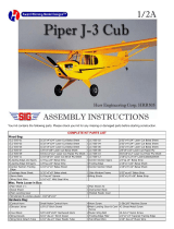
Your kit contains the following parts. Please check your kit for any missing or damaged parts before starting construction.
COMPLETE KIT PARTS LIST
Wood Bag:
1 LC-303-0 I 1/16"x4"x24" Laser Cut BALSA 1 LC-303-02 1/16"x4"x24" Laser Cut BALSA
1 LC-303-03 1/16"x4"x24" Laser Cut BALSA 1 LC-303-04 1/16"x4"x12" Laser Cut BALSA
1 LC-303-05 3/32"x4"x12" Laser Cut BALSA 1 LC-303-06 3/32"x4"x24" Laser Cut BALSA
1 LC-303-07 1/16"x4"x18" Laser Cut BALSA 1 LC-303-08 3mmx3.4"x6" Laser Cut POPLAR PLY
1 LC-303-09 1/16"x1.6"x3" Laser Cut BIRCH PLY 1 Former Braces 1/16"x1/16"x12" BALSA
4 Wing Trailing Edges 1/32" XI/2"x24" BALSA 2 Wing Leading Edges 3/16"x3/16"x24" BALSA
1 Wing Center Section Sheet 1/32"x3"x12" BALSA 4 Main Wing Spars 3/32"x1/4"x24" BALSA
4 Turbulator Spars 3/32"x3/32"x24" BALSA
Misc. Parts Loose in Box:
1 K-303 INSTRUCTIONS 1 K-303 PLAN B
1 K-303 PLAN A 1 PROPELLER
1 NYLON TIE WRAP
Hardware Bag:
3 Wing Dowels & Elevator Joiner 1/8"x3" BIRCH DOWEL 4 #2x1/2" SHEET METAL SCREW
The first thing that you need to do is to identify and mark the part numbers on the laser cut parts using the drawings on the
following pages as a guide.
It is possible that several of the laser cut parts may not be completely cut through. If this is the case you can free the part from
the sheet quickly using an X-acto knife.
NOTE: The slight discoloration on the edges of the laser cut parts may be removed by lightly sanding the edges with 400 grit
sandpaper.

.

.
Additional Items Required ( Not Included in Kit)
Note: These are parts that we have used and are familiar with. There are many other brands available and you may substitute other items that
you are more comfortable with or have on hand.
1 Motor 6 Volt 280 Class Electric Motor 1 Radio 3 Channel Radio with micro servos & Receiver
1 Speed Control 5 Amp Electronic Speed Control with BEC 1 Battery 7 Cell 270mAh NiCAD Battery or 7 cell 720Mah
NiMH Battery
3 Hinges Sig Easy Hinges #SH-710 or Du-Bro Kwik
Hinge #537
2 Pushrods Du-Bro #847 Micro Pushrod Assy.
1 Covering
Material
1 Roll covering material Plus Trim Colors 4 Wing hold down Rubber
bands
#32 rubber bands
General Note: Cover the plans with wax paper before assembling your model to prevent the parts from sticking to the plan.
Building the Tail Surfaces
1.
Glue R-1 and R-2 together over the plan to make the fin. Temporarily hinge the rudder to the fin (R-3). Do not glue the
hinges at this time.
2.
Sand one of the 1/8" dowels to 3/32" diameter. Join the elevators using this dowel. Use the plan of the stabilizer as a guide.
Trim the dowel as required to achieve the proper length.
3.
Temporarily hinge the elevators to the stabilizer. Do not glue the hinges at this time.
4.
Sand the tail surfaces smooth and round all of the edges except the bottom edge of the fin.
Building the Fuselage
5.
Make the two fuselage sides by gluing parts F-1A & F-1B together over the plan. Glue the F-2 doubler to the inside of the
fuselage sides. Be sure to make a right hand and a left hand side.
6.
Glue formers F
-
3 and F
-
4 into position on the right fuselage side. The formers should be 90 degrees to the fuselage side.
7.
Glue the left fuselage side into position on the formers. Glue F
-
5 into position at the front of the fuselage.
8.
Pull the rear of the fuselage sides together and hold with a clothespin.
9.
Glue the 1/16" sq. reinforcement to the top and bottom of F
-
6 and F
-
7 as shown on the plan.
10.
Place formers F
-
6 and F
-
7 into position and glue into position. Glue the rear end of the fuselage sides together.
11.
Glue F
-
8 into position on the top rear of the fuselage.
12.
Make the fuselage bottom by gluing parts F
-
9A & F
-
9B together and then glue to the bottom of the fuselage.
13.
Glue F
-
10 and F
-
11 into position on the top front of the fuselage.
14.
Glue F
-
12 to the front of the fuselage. The wide edge goes on the bottom.
15.
Position H
-
2 onto H
-
1 as shown on the plan and glue in place. Be sure that it is centered left and right.
16.
Glue parts H
-
3 to the bottom of H
-
1 as shown on the plan. Use H
-
4 as a spacer but be careful not to glue H
-
4 to H
-
1.
17.
Test fit the hatch on the fuselage. Trim as required to achieve a flush fit all around.
18.
Attach F
-
13 to the front of F
-
5 with the four sheet metal screws.
19.
Sand the fuselage smooth all over and set aside until needed.

.
Building the Wing
20.
Cover the wing plan with wax paper to prevent the parts from sticking to the plan.
21.
Pin the lower spar and the lower trailing edge to the plan. Align the inboard ends with the wing center line. The outboard
ends will extend past the last W
-
11 rib.
22.
Glue rib W
-
2 into position 90 degrees to the building board.
23.
Glue shear web "A" into position against the lower spar and rib W
-
2 as shown on the plan.
24.
Glue rib W
-
1 into position. The top of the rib should angle slightly toward the wing tip.
25.
Glue all of the remaining ribs into position. They should be 90 degrees to the building board.
26.
Glue the top spar, top trailing edge, turbulator spars and leading edge into place.
27.
Remove the wing from the plan. Trim the spars, leading edge and trailing edge flush with the end of W-11. Now glue the two
W
-
12 wing tip ribs to rib W
-
12.
28.
Glue the remaining shear webs into position.
29.
Cut and glue the top center section sheet into position as shown on the plan.
30.
Now build the right wing as you did the left.
31.
Sand both wing panels smooth and sand the leading edges round. Lightly round the edges of the wing tips.
32.
Cut slots in both W
-
1 ribs to accept the dihedral brace as shown on the plan.
33.
Slide the dihedral brace into position in the left wing. Position it tightly between the spars and forward against the shear web
and glue into position.
34.
Glue the right wing onto the left. Now test fit the wing onto the fuselage and sand the wing as required to produce a good fit
if needed.
Covering
35.
Sand all parts smooth with 200 grit sandpaper.
36.
Cover the model using your choice of material. We used Top Flite Monokote and it works very well. However there are many
other covering materials that can be used. We recommend using the lowest heat setting that will attach the covering to
minimize the shrinkage and reduce the possibilities of warping the structure of the model.
37.
Cut the windows from covering material using the patterns on the plan and apply to your model.
Note: After the model is covered you must check the tail surfaces and wing for warps or twists. If there are any they can be
removed by twisting the parts straight and heating the covering.
Final Assembly
38.
Cut the covering away from the fuselage where the stabilizer sits. Carefully remove the covering from the stabilizer in the
areas that it contacts the fuselage and glue the stabilizer to the fuselage.
39.
Glue the fin in place on the fuselage.
40.
Attach the elevators and rudder with the hinges and glue in place.
41.
Mount the servos to the fuselage sides using servo tape at the location shown on the plan.

.
42. Cut small pockets in the elevator and rudder and glue the control horns into position. They should angle forward slightly so
that the pushrod hole is aligned with the hinge line.
43.
Install the pushrods. They connect to the servos using Du-Bro Mini E/Z Connectors.
44.
Insert the wing hold down dowels and glue into place.
45.
Mount the receiver to the fuselage side with a piece of servo tape.
46.
Glue H-6 to H-4 to make the hatch latch. Place the latch into position on the hatch and glue parts H-5 into position to retain
the latch.
NOTE: Use extreme caution when gluing parts H
-
5 into position so as not to get any glue on the moving latch pieces.
47.
Connect the motor to the electronic speed control. Apply a small drop of oil to the bearings at each end of the motor.
48.
Glue the motor to the back side of F
-
B.
49.
Plug the speed control into the receiver. Charge and connect the battery and test the radio and power system WITHOUT
THE PROPELLER ATTACHED.
50.
Roughen up the motor shaft with sandpaper and apply a small amount of thick C/A glue and then press the propeller onto
the shaft.
51.
Find the proper balance point for the model with the wing attached by moving the battery forward & aft. Use a 1" sq. piece
of velcro to attach the battery in the model at this position.
52.
Adjust the control throws to the settings shown on the plan.
53.
Always pre
-flight your model thoroughly before each flight. It is your responsibility to verify that your model is airworthy.
Always follow established safety guidelines while starting and operating the engine, radio and while flying the model.
WARRANTY
Herr Engineering Corp. guarantees this kit to be free from defects in both materials and
workmanship at the time of purchase. This warranty does not cover any component damaged buy
use or modification. In no case shall Herr Engineering Corporation's liability exceed the original
cost of the purchased kit. Further Herr Engineering Corp. reserves the right to change or modify
this warranty without notice.
In that Herr Engineering Corporation has no control over the assembly or use, no liability shall be
assumed or accepted for any damage resulting from the use by the user during construction of the
kit or the use of the final user assembled product. By the act of building this kit and/or using the
final user assembled product, the user accepts all liability.
If the buyer and/or user is not prepared to accept all of the liability associated with this product, he
is advised to immediately return this kit in new and unused condition to the place of purchase for a
full refund.
© Copyright SIG Mfg. Co., Inc.
SIG MFG. CO., INC............Montezuma, Iowa 50171
-
0520
LIMIT OF LIABILITY:
In use of our products, Sig Mfg. Co.'s only obligation shall be to replace such quantity of the product proven to be defective.
User shall determine the suitability of the product for his or her intended use and shall assume all risk and liability in connection
therewith.
/