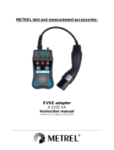
UNIKS EVSE User manual

Type
User manual

UNIKS EVSE is a versatile accessory designed to enhance the capabilities of your Multifunction Tester (MFT). It enables you to perform a wide range of measurements on EVSE charging points, including voltage, frequency, phase indication, phase sequence, RCD tests, insulation resistance, low ohm measurements, line and loop impedances, and more.

UNIKS EVSE is a versatile accessory designed to enhance the capabilities of your Multifunction Tester (MFT). It enables you to perform a wide range of measurements on EVSE charging points, including voltage, frequency, phase indication, phase sequence, RCD tests, insulation resistance, low ohm measurements, line and loop impedances, and more.

EVSE X7 Adapter EV
Charger Tester
.
REGISTER YOUR PRODUCT
www.uniks.it
The registration of your products will
allow you to stay informed about
news, take advantage of
advantageous discounts dedicated
to you for the purchase of
accessories and products for your
daily work.
Registration is free
4
Content
Operation Elements And Connectors………..5
References……………………………………………6
References
marked
on
instrument
or
in
instruction manual
6
Safety
References
………………………………………..7
Testing…………………………………………… 8
Purpose of the EVSE X7 accessory……...…….8
Test procedure:……………………………………..9
Proximity Pilot (PP) State (Cable Simulation)…..10
Control Pilot (CP) State (Vehicle Simulation)….10
CP Signal output terminals……………………….11
CP Error “E” simulation…………………………….12
Measuring terminals……………………………….12
Cleaning……………………………………………..12
ASSISTANCE………………………………………….14
WARRANTY CONDITIONS…………………………14
ASSISTANCE………………………………………….15
5
Operation Elements And Connectors
1. Type-2 plug
2. Slider switch for CP Mode selection
3. Test leads with 4mm safety
plugs for L1, L2, L3, N, PE, CP
and PP
Adapter is equipped with 0,5 m
test leads
6
References
References
marked
on
instrument
or
in
instruction manual
Warning of a potential
danger, follow with instruction
manual.
Reference! Please use utmost
attention.
Caution! Dangerous voltage.
Danger of electrical shock.
Ground terminal
Continuous double or
reinforced insulation category
II IEC 536 / DIN EN 61140.
Conformity symbol, the
instrument complies with the
valid directives. It complies
with the EMC Directive
(2014/30/ EU), Standard EN
61326 is fulfilled. It also
complies with the Low
Voltage Directive
(2014/35/EU) Standards EN
61010-1 and EN 61010-031.
Instrument fulfils the standard
(2012/19/EU) WEEE. This
marking indicates that this
product should not be dis-
posed with other household
wastes throughout the EU. To
prevent possible harm to the
environment or human health
from uncontrolled waste
disposal, recycle it responsibly
to promote the sustainable
reuse of material resources. To
return your used device,
please use the return and
collection systems or contact
the retailer where the product
was purchased. They can
take this product for
environmental safe recycling.
7
Safety references
Safety
References
The respective accident
prevention regulations
established by the
professional associations for
electrical systems and
equipment must be strictly
met at all times.
In order to avoid electrical
shock, the valid safety and
VDE regulations regarding
excessive contact voltages
must receive utmost
attention, when working with
voltages exceeding 120V
(60V) DC or 50V (25V) rms AC.
The values in brackets are
valid for limited ranges (as for
example medicine and
agriculture).
Measurements in dangerous
proximity of electrical systems
are only to be carried out in
compliance with the
instructions of a responsible
electronics technician, and
never alone.
If the operator’s safety is no
longer ensured, the
instrument is to be put out of
service and protected
against use. The safety is no
longer insured if the
instrument:
shows obvious damage
does not carry out the desired
measurements
has been stored for too long
under unfavorable conditions
has been subjected to
mechanical stress during
transport.
8
The instrument may only be
used within the operating
ranges as specified in the
technical data section.
Avoid any heating up of the
instrument by direct sunlight
to ensure perfect functioning
and long instrument life.
The opening of the instrument
for fuse replacement, for
example, may only be carried
out by professionals. Prior to
opening, the instrument has to
be switched off and
disconnected from any current
circuit.
The instrument may only be
used under those conditions
and for those purposes for
which it was conceived. For
this reason, in particular the
safety references, the
technical data including
environmental conditions and
the usage in dry
environments must be
followed.
When modifying or changing the
instrument, the operational safety
is no longer ensured.
Testing
Purpose of the EVSE X7 accessory
The UNIKS EVSE X7is an accessory
to support all relevant
measurements of a Multifunction
Tester (MFT) to simply wire
between the EVSE charging point
(Type-2 connector) and the
measurement inputs of the MFT.
All wires of the charging
connector are available: L1, L2,
L3, N, PE, CP and PP.
9
This allows to perform typical MFT
measurements: Voltage,
frequency, phase indication,
phase sequence, various RCD
tests and measurements,
insulation resistance, low ohm
measure- ments, line and loop
impedances, ....
Typical connection between
EVSE X7 and NOVA or NOVA PRO
(Multifunction Installation Testers).
Test procedure:
connect the needed 4 mm test
plugs of the UNIKS EVSE X7to
your MFT,
select CP Mode “A” with the
slider switch,
connect UNIKS EVSE X7to the
Type-2 connector of the
charging point,
select CP Mode “B” with the
slider switch, the charging point
should show “ready to charge”,
select CP Mode “C” with the
slider switch, the charging point
should start charging,
perform all measurements in
active stage of the charging
point (voltage and similar),
after you completed all your
measurements select CP Mode
10
A” with the slider switch to stop
charging,
unplug UNIKS EVSE X7from the
charging point.
Proximity Pilot (PP) State (Cable
Simulation)
The UNIKS EVSE X7is configured
internally to setup 32 A current
capability.
Control Pilot (CP) State (Vehicle
Simulation)
With the CP Mode slider switch
various vehicle states can be
simulated. Vehicle states are
simulated with different
resistances connected between
CP and PE conductors.
Correlation between resistance
and vehicle states is shown in
Table below
11
Vehicle
State
State
Description
CP-
PE
CP
A
Electric
vehicle not
connected
Open
(∞)
±12V @
1KHz
B
Vehicle
connecte
d, not
ready to
charge
2.74K
Ω
+9V/-12V
@ 1KHz
C
Electric
vehicle
connected
ready to
charge,
ventilation
not
required
882Ω
+6V/-12V
@ 1KHz
[E]
CP Error „E“
(see below)
0V
Testing
CP Signal output terminals
CP output terminals are short
connected to the CP and PE
conductors of the tested
charging station via the test
cable. Use an oscilloscope to
check the waveform and
amplitude of the CP signal.
Control Pilot function uses Pulse
Width Modulation (PWM) to
code communication between a
vehicle and charging station. The
duty cycle of the PWM signal
defines the possible available
charging current, while
amplitude defines charger state.
12
For details of communication
protocol please refer to IEC/EN
61851-1 and the documentation
of the manufacturer of the
charging station.
Important note: In the case of
wrong wiring of the charging
station, low signal CP test
terminals can get high, live
hazard voltage.
CP Error “E” simulation
“E” - CP Error simulation could be
realized by pushing the slider
switch into (spring loaded)
position [E]. This will simulate
behavior of the station when
there is a short circuit between CP
and PE through internal diode
(acc. to standard IEC/EN 61851-
1). In the case of CP Error (“E is
pushed), result should be
aborting of the charging process
and new charging process is
prevented.
Measuring terminals
All terminals inside the Type-2
connector (L1, L2, L3, N, PE, CP
and PP) are available on 4 mm
safety connectors with double
insulated wires according to IEC
61010-031. It is allowed to use
these for measuring purposes
only. It is not allowed to draw cur-
rent over a longer period or
supply anything else. An
appropriate measurement
instrument is needed.
Cleaning
If the instrument is dirty after daily
usage, it is advised to clean it by
using a humid cloth and a mild
household detergent. Prior to
cleaning, ensure that instrument is
switched off and disconnected
from external voltage supply and
13
any other instruments connect-
ed (such as UUT, control
instruments, etc.).
Never use acid detergents or
dissolvent for cleaning.
Input Voltage:
230 / 400 V 3~
50 / 60 Hz
Measurement
Category:
CAT II 300V
Main socket
rating:
max. 10A
PP simulation:
configurazione
interna a 32 A
CP simulation:
Stati A, B, C
Error simulation:
Errore CP "E"
Test connector
type:
IEC62196-2 Tipo
2 maschio
Type 2 male
Test cable
length:
0,5 m
Working
temperature:
0 ... +40ºC
Storage
temperature:
-10 ... +50ºC
Humidity:
0-80% RH
Compliance to:
IEC 61010-1 /
IEC 61010-031
14
ASSISTANCE
WARRANTY CONDITIONS
This instrument is warranted against
defects in materials and
workmanship, in accordance with
the general terms and conditions.
During the warranty period,
defective parts can be replaced,
but the manufacturer reserves the
right to repair or replace the
product. If the instrument is to be
returned to the after - sales service
or to a dealer transportation is
borne by the customer. The
shipment must, however, be
agreed. Attached to dispatch an
explanatory note about the
reasons of the instrument must
always be inserted. For shipping
only use the original packaging.
Any damage caused by the use of
non-original packing shall be
charged to the customer. The
manufacturer accepts no
responsibility for damage caused
to people or objects.
The warranty does not apply in
the following cases:
Repair and / or replacement of
accessories and battery (not
covered by warranty).
Repairs made necessary
because of a misuse of the
instrument or of its use with no
compatible devices.
Repairs made necessary due to
improper packaging.
Repairs made necessary due to
work carried out by
unauthorized personnel.
Modification of the instrument
without the explicit permission
of the manufacturer.
Use not provided for in the
specifications of the instrument
or in the instruction manual.
15
The content of this manual may not
be reproduced in any form without
the permission of the
manufacturer.
Our products are patented and
their trademarks. The manufacturer
reserves the right to change
specifications and prices if this is
due to technological
improvements.
ASSISTANCE
If the instrument does not operate
properly, before contacting the
Customer Service, check the status
of the battery and wear of the
cables and replace them if
necessary. If the instrument
continues to manifest malfunctions
check if the procedure of use of
the same is in accordance with
what is indicated in this manual. If
the instrument is to be returned to
the after - sales service or to a
dealer transportation is borne by
the customer. The shipment must,
however, be agreed. Attached to
dispatch an explanatory note
about the reasons of the instrument
must always be inserted. For
shipping only use the original
packaging; any damage caused
by the use of non-original packing
shall be charged to the customer.
16
  • Page 1 1
  • Page 2 2
  • Page 3 3
  • Page 4 4
  • Page 5 5
  • Page 6 6
  • Page 7 7
  • Page 8 8
  • Page 9 9
  • Page 10 10
  • Page 11 11
  • Page 12 12
  • Page 13 13
  • Page 14 14
  • Page 15 15
  • Page 16 16

UNIKS EVSE User manual

Type
User manual

UNIKS EVSE is a versatile accessory designed to enhance the capabilities of your Multifunction Tester (MFT). It enables you to perform a wide range of measurements on EVSE charging points, including voltage, frequency, phase indication, phase sequence, RCD tests, insulation resistance, low ohm measurements, line and loop impedances, and more.

Ask a question and I''ll find the answer in the document

Finding information in a document is now easier with AI