Gigabyte Z790 AORUS MASTER X Owner's manual
- Category
- Motherboards
- Type
- Owner's manual

Z790 AORUS MASTER X
User's Manual
Rev. 1001
GIGABYTE will reduce paper use in order to fulll the responsibilities of a global citizen.
Also, to reduce the impacts on global warming, the packaging materials of this product
are recyclable and reusable. GIGABYTE works with you to protect the environment.
For more product details, please visit GIGABYTE's website.

Copyright
© 2023 GIGA-BYTE TECHNOLOGY CO., LTD. All rights reserved.
The trademarks mentioned in this manual are legally registered to their respective owners.
Disclaimer
Information in this manual is protected by copyright laws and is the property of GIGABYTE.
Changes to the specications and features in this manual may be made by GIGABYTE without
prior notice. No part of this manual may be reproduced, copied, translated, transmitted, or
published in any form or by any means without GIGABYTE's prior written permission.
For detailed product information, carefully read the User's Manual.
For quick set-up of the product, refer to the Quick Installation Guide on GIGABYTE's
website.
https://download.gigabyte.com/FileList/Manual/mb_manual_installation-guide_12QM-100xR.pdf
For product-related information, check on our website at: https://www.gigabyte.com
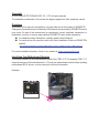
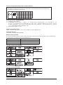
Identifying Your Motherboard Revision
The revision number on your motherboard looks like this: "REV: X.X." For example, "REV: 1.0"
means the revision of the motherboard is 1.0. Check your motherboard revision before updating
motherboard BIOS, drivers, or when looking for technical information.
Example:

- 3 -
Table of Contents
Chapter 1 Product Introduction .......................................................................................4
1-1 Motherboard Layout ......................................................................................... 4
1-2 Motherboard Block Diagram ............................................................................ 5
Chapter 2 Hardware Installation .....................................................................................6
2-1 Installation Precautions .................................................................................... 6
2-2 Product Specications ...................................................................................... 7
2-3 Installing the CPU and CPU Cooler ............................................................... 11
2-4 Installing the Memory ..................................................................................... 14
2-5 Installing an Expansion Card ......................................................................... 15
2-6 Back Panel Connectors .................................................................................. 16
2-7 Onboard Buttons, Voltage Measurement Points and LEDs ........................... 18
2-8 Internal Connectors ........................................................................................ 20
Chapter 3 BIOS Setup ..................................................................................................33
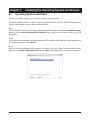
Chapter 4 Installing the Operating System and Drivers ................................................ 35
4-1 Operating System Installation ........................................................................ 35
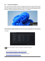
4-2 Drivers Installation .......................................................................................... 36
Chapter 5 Appendix ......................................................................................................37
5-1 Conguring a RAID Set .................................................................................. 37
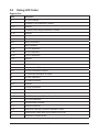
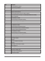
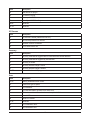
5-2 Debug LED Codes ......................................................................................... 38
Regulatory Notices .................................................................................................... 42
Contact Us ................................................................................................................ 45

- 4 -
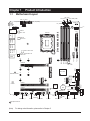
1-1 Motherboard Layout
(Note) For debug code information, please refer to Chapter 5.
Temperature sensor
Chapter 1 Product Introduction
M2_WIFI
DP
U32G2_1
U320G_1
U32G2_2
U320G_2
U32G2_3
HU32C
U32G2
LAN
LGA1700 ATX
AUDIO
DDR5_A1
DDR5_A2
DDR5_B1
DDR5_B2
BAT
Intel® Z790
CLR_CMOS
M_BIOS
THB_C1
CODEC
ESS ES9118 DAC
PCIEX16
PCIEX1
PCIEX4
F_U320G
F_U32_1
F_U32_2
SYS_FAN7_PUMP
SYS_FAN8_PUMP
DB_PORT (Note)
EC_TEMP1
EC_TEMP2
SYS_FAN1
SYS_FAN2
80110
M2C_CPU
80110
M2A_CPU
80110
M2Q_SB
80
M2P_SB
80
M2M_SB
Z790 AORUS MASTER X
RST_SW RSTF_USB2ARGB_V2_1 NOISE_
SENSOR
F_AUDIO
SYS_FAN3 F_USB1LED_CARGB_V2_3 SYS_FAN4 SPI_TPM F_PANEL
CPU_OPT SYS_FAN6_PUMP
CPU_FAN
SYS_FAN5_
PUMP
iTE®
Super I/O
ARGB_V2_2
PW_SW
ATX_12V_2X4_2
ATX_12V_2X4_1
USB 2.0 Hub
USB 3.2
Gen 1 Hub
USB 3.2
Gen 2 Hub
USB 3.2
Gen 1 Hub
USB 3.2 Gen 2 Hub
VGA CPU
BOOT DRAM
REAR_
BUTTON
U32
Marvell® AQtion AQC113C
10GbE LAN
THB_USB4_C2 SATA3
5 7
4 6

- 5 -
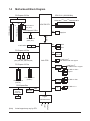
1-2 Motherboard Block Diagram
LGA1700 CPU
CPU CLK+/- (80~800 MHz)
DMI 4.0
4 SATA 6Gb/s
eSPI
Bus
SPI
Bus
DDI
PCI Express 4.0 Bus
PCI Express 3.0 Bus
Line Out
MIC
S/PDIF Out
CODEC
+
ESS ES9118 DAC
iTE®
Super I/O
8 USB 3.2 Gen 1
1 USB Type-C®,
with USB 3.2 Gen 1 support
Intel® Z790
x4 x1
x4
x4
x4 x4
DisplayPort
1 PCI Express x4
(PCIEX4)
1 PCI Express x1
(PCIEX1) USB 3.2
Gen 1 Hub
USB 3.2
Gen 2 Hub
4 USB 2.0/1.1
USB 2.0
Hub
BIOS
TPM
PCI Express 5.0 Bus
PCI Express 4.0 Bus
1 M.2 Socket 3
(M2A_CPU)
3 M.2 Socket 3
(M2Q_SB, M2P_SB, M2M_SB)
3 USB Type-C®,
with USB 3.2 Gen 2x2 support
7 USB 3.2 Gen 2
Type-A
DDR5 5600 (Note)/5200 (Note)/4800/4400 MT/s
x16
x16
1 PCI Express x16
1 PCI Express x8
1 M.2 Socket 3
(M2C_CPU)
x4x8
Switch
or
PCI Express Bus
CNVi
x1
M.2 WIFI
LAN
RJ45
x2
Marvell® AQtion
AQC113C
10GbE LAN
(Note) Actual support may vary by CPU.

- 6 -
2-1 Installation Precautions
The motherboard contains numerous delicate electronic circuits and components which can become
damaged as a result of electrostatic discharge (ESD). Prior to installation, carefully read the user's
manual and follow these procedures:
•Prior to installation, make sure the chassis is suitable for the motherboard.
•Prior to installation, do not remove or break motherboard S/N (Serial Number) sticker or
warranty sticker provided by your dealer. These stickers are required for warranty validation.
•Always remove the AC power by unplugging the power cord from the power outlet before
installing or removing the motherboard or other hardware components.
•When connecting hardware components to the internal connectors on the motherboard, make
sure they are connected tightly and securely.
•When handling the motherboard, avoid touching any metal leads or connectors.
•It is best to wear an electrostatic discharge (ESD) wrist strap when handling electronic
components such as a motherboard, CPU or memory. If you do not have an ESD wrist strap,
keep your hands dry and rst touch a metal object to eliminate static electricity.
•Prior to installing the motherboard, please have it on top of an antistatic pad or within an
electrostatic shielding container.
•Before connecting or unplugging the power supply cable from the motherboard, make sure
the power supply has been turned off.
•Before turning on the power, make sure the power supply voltage has been set according to
the local voltage standard.
•Before using the product, please verify that all cables and power connectors of your hardware
components are connected.
•To prevent damage to the motherboard, do not allow screws to come in contact with the
motherboard circuit or its components.
•Make sure there are no leftover screws or metal components placed on the motherboard or
within the computer casing.
•Do not place the computer system on an uneven surface.
•Do not place the computer system in a high-temperature or wet environment.
•Turning on the computer power during the installation process can lead to damage to system
components as well as physical harm to the user.
•If you are uncertain about any installation steps or have a problem related to the use of the
product, please consult a certied computer technician.
•If you use an adapter, extension power cable, or power strip, ensure to consult with its
installation and/or grounding instructions.
Chapter 2 Hardware Installation

- 7 -
2-2 ProductSpecications
CPU LGA1700 socket: Support for the 14th, 13th, and 12th Generation Intel® Core™,
Pentium® Gold and Celeron® Processors
(Go to GIGABYTE's website for the latest CPU support list.)
L3 cache varies with CPU
Chipset Intel® Z790 Express Chipset
Memory 14th and 13th Generation Intel® Core™ i9/i7 Processors:
- Support for DDR5 5600/5200/4800/4400 MT/s memory modules
13th Generation Intel® Core™ i5/i3 and 12th Generation Intel® Core™, Pentium®
Gold and Celeron® Processors:
- Support for DDR5 4800/4400 MT/s memory modules
4 x DDR5 DIMM sockets supporting up to 192 GB (48 GB single DIMM capacity)
of system memory
Dual channel memory architecture
Support for ECC Un-buffered DIMM 1Rx8/2Rx8 memory modules (operate in
non-ECC mode)
Support for non-ECC Un-buffered DIMM 1Rx8/2Rx8/1Rx16 memory modules
Support for Extreme Memory Prole (XMP) memory modules
(The CPU and memory conguration may affect the supported memory types, data
rate (speed), and number of DRAM modules, please refer to "Memory Support List"
on GIGABYTE's website for more information.)
Onboard
Graphics
Integrated Graphics Processor-Intel® HD Graphics support:
- 1 x DisplayPort, supporting a maximum resolution of 4096x2304@60 Hz
* Support for DisplayPort 1.2 version and HDCP 2.3
(Graphics specications may vary depending on CPU support.)
Audio Realtek® ALC1220-VB CODEC
* The front panel line out jack supports DSD audio.
ESS ES9118 DAC chip
Support for DTS:X® Ultra
High Denition Audio
2/4/5.1-channel
* You can change the functionality of an audio jack using the audio software. To congure
5.1-channel audio, access the audio software for audio settings.
Support for S/PDIF Out
LAN Marvell® AQtion AQC113C 10GbE LAN chip
(10 Gbps/5 Gbps/2.5 Gbps/1 Gbps/100 Mbps)
Wireless
Communication
Module
Qualcomm® Wi-Fi 7 QCNCM865 (PCB rev. 1.0)
- 802.11a, b, g, n, ac, ax, be, supporting 2.4/5/6 GHz carrier frequency bands
- BLUETOOTH 5.3
- Support for 11be 320MHz wireless standard
MediaTek Wi-Fi 7 MT7927, RZ738 (PCB rev. 1.1)
- 802.11a, b, g, n, ac, ax, be, supporting 2.4/5/6 GHz carrier frequency bands
- BLUETOOTH 5.3
- Support for 11be 320MHz wireless standard
Intel® Wi-Fi 7 BE200 (PCB rev. 1.2)
- 802.11a, b, g, n, ac, ax, be, supporting 2.4/5/6 GHz carrier frequency bands
- BLUETOOTH 5.3
- Support for 11be 320MHz wireless standard
(Actual data rate may vary depending on environment and equipment.)

- 8 -
Expansion Slots CPU:
- 1 x PCI Express x16 slot, supporting PCIe 5.0 and running at x16 (PCIEX16)
* The PCIEX16 slot shares bandwidth with the M2C_CPU connector. The PCIEX16
slot operates at up to x8 mode when a device is installed in the M2C_CPU connector.
* For optimum performance, if only one PCI Express graphics card is to be installed,
be sure to install it in the PCIEX16 slot.
Chipset:
- 1 x PCI Express x16 slot, supporting PCIe 3.0 and running at x4 (PCIEX4)
- 1 x PCI Express x16 slot, supporting PCIe 3.0 and running at x1 (PCIEX1)
Storage Interface CPU:
- 1 x M.2 connector (Socket 3, M key, type 25110/2280 PCIe 5.0 x4/x2 SSD
support) (M2C_CPU)
- 1 x M.2 connector (Socket 3, M key, type 22110/2280 PCIe 4.0 x4/x2 SSD
support) (M2A_CPU)
Chipset:
- 1 x M.2 connector (Socket 3, M key, type 22110/2280 PCIe 4.0 x4/x2 SSD
support) (M2Q_SB)
- 1 x M.2 connector (Socket 3, M key, type 2280 PCIe 4.0 x4/x2 SSD support)
(M2P_SB)
- 1 x M.2 connector (Socket 3, M key, type 2280 SATA and PCIe 4.0 x4/x2 SSD
support) (M2M_SB)
- 4 x SATA 6Gb/s connectors
RAID 0, RAID 1, RAID5, and RAID 10 support for NVMe SSD storage devices
RAID 0, RAID 1, RAID5, and RAID 10 support for SATA storage devices
USB Chipset:
- 3 x USB Type-C® ports, with USB 3.2 Gen 2x2 support (2 ports on the back
panel, 1 port available through the internal USB header)
Chipset+2 USB 3.2 Gen 2 Hubs:
- 1 x USB Type-C® port on the back panel, with USB 3.2 Gen 1 support
- 7 x USB 3.2 Gen 2 Type-A ports (red) on the back panel
Chipset+2 USB 3.2 Gen 1 Hubs:
- 8 x USB 3.2 Gen 1 ports (4 ports on the back panel, 4 ports available through
the internal USB headers)
Chipset+USB 2.0 Hub:
- 4 x USB 2.0/1.1 ports available through the internal USB headers
Internal
Connectors
1 x 24-pin ATX main power connector
2 x 8-pin ATX 12V power connectors
1 x CPU fan header
1 x CPU fan/water cooling pump header
4 x system fan headers
4 x system fan/water cooling pump headers
3 x addressable RGB Gen2 LED strip headers
1 x RGB LED strip header
5 x M.2 Socket 3 connectors
4 x SATA 6Gb/s connectors

- 9 -
Internal
Connectors
1 x front panel header
1 x front panel audio header
1 x USB Type-C® header, with USB 3.2 Gen 2x2 support
2 x USB 3.2 Gen 1 headers
2 x USB 2.0/1.1 headers
1 x noise detection header
2 x Thunderbolt™ add-in card connectors
1 x Trusted Platform Module header (For the GC-TPM2.0 SPI/GC-TPM2.0 SPI 2.0/
GC-TPM2.0 SPI V2 module only)
1 x power button
1 x reset button
1 x reset jumper
1 x Clear CMOS jumper
2 x temperature sensor headers
Voltage Measurement Points
Back Panel
Connectors
1 x Q-Flash Plus button
1 x Clear CMOS button
2 x SMA antenna connectors (2T2R)
1 x DisplayPort
1 x USB Type-C® port, with USB 3.2 Gen 1 support
2 x USB Type-C® ports, with USB 3.2 Gen 2x2 support
7 x USB 3.2 Gen 2 Type-A ports (red)
4 x USB 3.2 Gen 1 ports
1 x RJ-45 port
1 x optical S/PDIF Out connector
2 x audio jacks
I/O Controller iTE® I/O Controller Chip
Hardware
Monitor
Voltage detection
Temperature detection
Fan speed detection
Water cooling ow rate detection
Fan fail warning
Fan speed control
* Whether the fan (pump) speed control function is supported will depend on the fan
(pump) you install.
Noise detection
BIOS 1 x 256 Mbit ash
Use of licensed AMI UEFI BIOS
PnP 1.0a, DMI 2.7, WfM 2.0, SM BIOS 2.7, ACPI 5.0

- 10 -
&Please visit the SERVICE/SUPPORT\Utility page on GIGABYTE's website to download the latest version
of apps.
https://www.gigabyte.com/Support/Utility/Motherboard?m=ut
Unique Features Support for GIGABYTE Control Center (GCC)
* Available applications in GCC may vary by motherboard model. Supported functions
of each application may also vary depending on motherboard specications.
Support for Q-Flash
Support for Q-Flash Plus
Support for Smart Backup
Bundled
Software
Norton® Internet Security (OEM version)
LAN bandwidth management software
Operating
System Support for Windows 11 64-bit
Form Factor E-ATX Form Factor; 30.5cm x 26.0cm
* GIGABYTE reserves the right to make any changes to the product specications and product-related information without
prior notice.

- 11 -
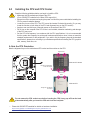
2-3 Installing the CPU and CPU Cooler
Read the following guidelines before you begin to install the CPU:
•Make sure that the motherboard supports the CPU.
(Go to GIGABYTE's website for the latest CPU support list.)
•Always turn off the computer and unplug the power cord from the power outlet before installing the
CPU to prevent hardware damage.
•Locate the pin one of the CPU. The CPU cannot be inserted if oriented incorrectly. (Or you may
locate the notches on both sides of the CPU and alignment keys on the CPU socket.)
•Apply an even and thin layer of thermal grease on the surface of the CPU.
•Do not turn on the computer if the CPU cooler is not installed, otherwise overheating and damage
of the CPU may occur.
•Set the CPU host frequency in accordance with the CPU specications. It is not recommended
that the system bus frequency be set beyond hardware specications since it does not meet the
standard requirements for the peripherals. If you wish to set the frequency beyond the standard
specications, please do so according to your hardware specications including the CPU, graphics
card, memory, hard drive, etc.
A. Note the CPU Orientation
Note the alignment keys on the motherboard CPU socket and the notches on the CPU.
&Please visit GIGABYTE's website for details on hardware installation.
https://www.gigabyte.com/WebPage/210/quick-guide.html?m=sw
Notch
Notch
LGA1700 CPU
Triangle Pin One Marking
on the CPU
Alignment Key
LGA1700 CPU Socket
Triangle Pin One Marking
of the CPU Socket
Alignment Key
Do not remove the CPU socket cover before inserting the CPU. It may pop off from the load
plate automatically after you insert the CPU and close the load plate.

- 12 -
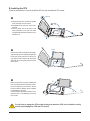
B. Installing the CPU
Follow the steps below to correctly install the CPU into the motherboard CPU socket.
w
u
Do not force to engage the CPU socket locking lever when the CPU is not installed correctly
as this would damage the CPU and CPU socket.
v
jGently press the CPU socket lever handle
down and away from the socket.
kCompletely lift up the CPU socket lock-
ing lever.
lUse the finger tab on the side of the
metal load plate to lift open the metal
load plate with the plastic protective cover
attached to it.
Hold the CPU with your ngers by the edges.
Align the CPU pin one marking (triangle) with
the pin one corner of the CPU socket (or you
may align the CPU notches with the socket
alignment keys) and gently insert the CPU
into position.
Make sure the CPU is properly installed and
then close the load plate. The plastic protec-
tive cover will pop off, just remove it. Secure
the lever under its retention tab to complete
the installation of the CPU.
* Always replace the plastic protective cover
when the CPU is not installed to protect the
CPU socket.
j
k
l
Finger Tab
Pin One
j
k
l

- 13 -
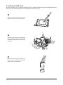
C. Installing the CPU Cooler
Be sure to install the CPU cooler after installing the CPU. (Actual installation process may differ depending the
CPU cooler to be used. Refer to the user's manual for your CPU cooler.)
u
v
Apply an even and thin layer of thermal
grease on the surface of the installed CPU.
Place the cooler atop the CPU, aligning the
four push pins through the pin holes on the
motherboard. Push down on the push pins
diagonally.
j
j
k
k
w
Finally, attach the power connector of
the CPU cooler to the CPU fan header
(CPU_FAN) on the motherboard.
CPU_FAN

- 14 -
2-4 Installing the Memory
Read the following guidelines before you begin to install the memory:
•Make sure that the motherboard supports the memory. It is recommended that memory of the same
capacity, brand, speed, and chips be used. (Go to GIGABYTE's website for the latest supported
memory speeds and memory modules.)
•Always turn off the computer and unplug the power cord from the power outlet before installing the
memory to prevent hardware damage.
•Memory modules have a foolproof design. A memory module can be installed in only one direction.
If you are unable to insert the memory, switch the direction.
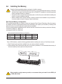
DualChannelMemoryConguration
This motherboard provides four memory sockets and supports Dual Channel Technology. After the memory
is installed, the BIOS will automatically detect the specications and capacity of the memory. Enabling Dual
Channel memory mode will double the original memory bandwidth.
The four memory sockets are divided into two channels and each channel has two memory sockets as following:
Channel A: DDR5_A1, DDR5_A2
Channel B: DDR5_B1, DDR5_B2
Due to CPU limitations, read the following guidelines before installing the memory in Dual Channel mode.
1. Dual Channel mode cannot be enabled if only one memory module is installed.
2. When enabling Dual Channel mode with two or four memory modules, it is recommended that memory of
the same capacity, brand, speed, and chips be used.
DDR5_A1
DDR5_A2
DDR5_B1
DDR5_B2
* Recommended Dual Channel Memory Conguration:
DDR5_A1 DDR5_A2 DDR5_B1 DDR5_B2
2 Modules - - DS/SS - - DS/SS
4 Modules DS/SS DS/SS DS/SS DS/SS
(SS=Single-Sided, DS=Double-Sided, "- -"=No Memory)
When installing a single memory module, we recommend that you install it in the DDR5_A2
or DDR5_B2 socket.

- 15 -
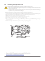
2-5 Installing an Expansion Card
Read the following guidelines before you begin to install an expansion card:
•Make sure the motherboard supports the expansion card. Carefully read the manual that came
with your expansion card.
•Always turn off the computer and unplug the power cord from the power outlet before installing an
expansion card to prevent hardware damage.
Follow the steps below to correctly install your expansion card in the expansion slot.
1. Locate an expansion slot that supports your card. Remove the metal slot cover from the chassis back panel.
2. Align the card with the slot, and press down on the card until it is fully seated in the slot.
3. Make sure that the expansion card is fully seated in its slot.
4. Secure the card's metal bracket to the chassis back panel with a screw.
5. After installing all expansion cards, replace the chassis cover(s).
6. Turn on your computer. If necessary, go to BIOS Setup to make any required BIOS changes for your
expansion card(s).
7. Install the driver provided with the expansion card in your operating system.
PCIEX16 Slot
&Please visit GIGABYTE's website for details on using PCIe EZ-Latch Plus.
https://www.gigabyte.com/WebPage/922/removePCIE.html

- 16 -
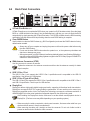
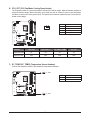
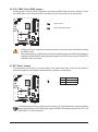
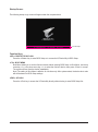
Q-Flash Plus Button (Note)
Q-Flash Plus allows you to update the BIOS when your system is off (S5 shutdown state). Save the latest
BIOS on a USB thumb drive and plug it into the dedicated port, and then you can now ash the BIOS
automatically by simply pressing the Q-Flash Plus button. The QFLED will ash when the BIOS matching
and ashing activities start and will stop ashing when the main BIOS ashing is complete.
Clear CMOS Button
Use this button to clear the CMOS values (e.g. BIOS conguration) and reset the CMOS values to factory
defaults when needed.
2-6 Back Panel Connectors
•Always turn off your computer and unplug the power cord from the power outlet before using
the clear CMOS button.
•Do not use the clear CMOS button when the system is on, or the system may shutdown and
data loss or damage may occur.
•After system restart, go to BIOS Setup to load factory defaults (select Load Optimized Defaults) or
manually congure the BIOS settings (please navigate to the "BIOS Setup" page of GIGABYTE's
website for more information).
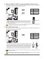
SMA Antenna Connectors (2T2R)
Use this connector to connect an antenna.
USB 3.2 Gen 1 Port
The USB 3.2 Gen 1 port supports the USB 3.2 Gen 1 specication and is compatible to the USB 2.0
specication. Use this port for USB devices.
USB 3.2 Gen 2 Type-A Port (Red)
The USB 3.2 Gen 2 port supports the USB 3.2 Gen 2 specication and is compatible to the USB 3.2 Gen 1
and USB 2.0 specication. Use this port for USB devices.
DisplayPort
DisplayPort delivers high quality digital imaging and audio, supporting bi-directional audio transmission.
DisplayPort can support HDCP 2.3 content protection mechanisms. You can use this port to connect your
DisplayPort-supported monitor. Note: The DisplayPort Technology can support a maximum resolution of
4096x2304@60 Hz but the actual resolutions supported depend on the monitor being used.
Tighten the antennas to the antenna connectors and then aim the antennas correctly for better
signal reception.
After installing the DisplayPort device, make sure to set the default sound playback device to
DisplayPort. (The item name may differ depending on your operating system.)
•When removing the cable connected to a back panel connector, rst remove the cable from your
device and then remove it from the motherboard.
•When removing the cable, pull it straight out from the connector. Do not rock it side to side to
prevent an electrical short inside the cable connector.

- 17 -
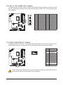
USB 3.2 Gen 2 Type-A Port (Q-Flash Plus Port)
The USB 3.2 Gen 2 port supports the USB 3.2 Gen 2 specication and is compatible to the USB 3.2 Gen 1
and USB 2.0 specication. Use this port for USB devices. Before using Q-Flash Plus (Note), make sure to
insert the USB ash drive into this port rst.
USB Type-C® Port (with USB 3.2 Gen 1 Support)
The reversible USB port supports the USB 3.2 Gen 1 specication and is compatible to the USB 2.0
specication. Use this port for USB devices.
Line Out/Front Speaker Out
The line out jack.
Mic In/Rear Speaker Out
The Mic in jack.
Optical S/PDIF Out Connector
This connector provides digital audio out to an external audio system that supports digital optical audio.
Before using this feature, ensure that your audio system provides an optical digital audio in connector.
USB Type-C® Port (with USB 3.2 Gen 2x2 Support)
The reversible USB port supports the USB 3.2 Gen 2x2 specication and is compatible to the USB 3.2
Gen 2, USB 3.2 Gen 1, and USB 2.0 specications. Use this port for USB devices.
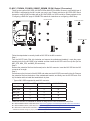
RJ-45 LAN Port
The Gigabit Ethernet LAN port provides Internet connection at up to 10 Gbps data rate. The following
describes the states of the LAN port LEDs.
&Please visit GIGABYTE's website for details on conguring the audio software.
https://www.gigabyte.com/WebPage/698/realtek1220-audio.html
Audio Jack Congurations:
Jack Headphone/
2-channel 4-channel 5.1-channel
Line Out/Front Speaker Out aaa
Mic In/Rear Speaker Out a a
Front Panel Line Out/Side Speaker Out
Front Panel Mic In/Center/Subwoofer
Speaker Out a
You can change the functionality of an audio jack using the audio software. To congure 5.1-channel
audio, access the audio software for audio settings.
(Note) To enable the Q-Flash Plus function, please navigate to the "Unique Features" page of GIGABYTE's
website for more information.
Speed LED Activity LED
LAN Port
Speed LED:
State Description
Green 10 Gbps data rate
Orange 5 Gbps/ 2.5 Gbps/ 1 Gbps/
100 Mbps data rate
Activity LED:
State Description
Blinking Data transmission or receiving is occurring
On No data transmission or receiving is occurring

- 18 -
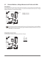
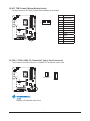
2-7 Onboard Buttons, Voltage Measurement Points and LEDs
Quick Buttons
This motherboard has 2 quick buttons: power button and reset button. The power button and reset button allow
users to quickly turn on/off or reset the computer in an open-case environment when they want to change
hardware components or conduct hardware testing.
PW_SW: Power Button
RST_SW: Reset Button
RST_SW
PW_SW
The reset button provides you with several functions to use. To remap the button to perform different
tasks, please navigate to the "BIOS Setup" page of GIGABYTE's website and search for "RST_SW
(MULTIKEY)" for more information.
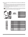
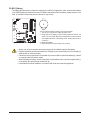
Voltage Measurement Points
Use a multimeter to measure the following motherboard voltages.
VDD2_CPU
VCCIN_AUX_CPU
VCCGT
V1P8_CPU
V1P05_CPU
V0P82_PCH
111111

- 19 -
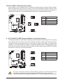
CPU: CPU status LED
DRAM: Memory status LED
VGA: Graphics card status LED
BOOT: Operating system status LED
CPU DRAM
VGA BOOT
Status LEDs
The status LEDs show whether the CPU, memory, graphics card, and operating system are working properly
after system power-on. If the CPU/DRAM/VGA LED is on, that means the corresponding device is not working
normally; if the BOOT LED is on, that means you haven't entered the operating system yet.

- 20 -
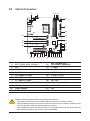
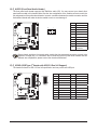
2-8 Internal Connectors
Read the following guidelines before connecting external devices:
•First make sure your devices are compliant with the connectors you wish to connect.
•Before installing the devices, be sure to turn off the devices and your computer. Unplug the power
cord from the power outlet to prevent damage to the devices.
•After installing the device and before turning on the computer, make sure the device cable has
been securely attached to the connector on the motherboard.
1) ATX_12V_2X4_1/ATX_12V_2X4_2
2) ATX
3) CPU_FAN
4) SYS_FAN1/2/3/4
5) SYS_FAN5/6/7/8_PUMP
6) CPU_OPT
7) EC_TEMP1/EC_TEMP2
8) ARGB_V2_1/ARGB_V2_2/ARGB_V2_3
9) LED_C
10) NOISE_SENSOR
11) SATA3 4/5/6/7
12) M2C_CPU/M2A_CPU/
M2Q_SB/M2P_SB/M2M_SB
13) F_PANEL
14) F_AUDIO
15) F_U320G
16) F_U32_1/F_U32_2
17) F_USB1/F_USB2
18) SPI_TPM
19) THB_C1/THB_USB4_C2
20) CLR_CMOS
21) RST
22) BAT
13 2018 21722
16
15
2
5
19
11
12
17 5414 4
4 1
109
8
12
12
12
12
3 5 76
8
Page is loading ...
Page is loading ...
Page is loading ...
Page is loading ...
Page is loading ...
Page is loading ...
Page is loading ...
Page is loading ...
Page is loading ...
Page is loading ...
Page is loading ...
Page is loading ...
Page is loading ...
Page is loading ...
Page is loading ...
Page is loading ...
Page is loading ...
Page is loading ...
Page is loading ...
Page is loading ...
Page is loading ...
Page is loading ...
Page is loading ...
Page is loading ...
Page is loading ...
-
 1
1
-
 2
2
-
 3
3
-
 4
4
-
 5
5
-
 6
6
-
 7
7
-
 8
8
-
 9
9
-
 10
10
-
 11
11
-
 12
12
-
 13
13
-
 14
14
-
 15
15
-
 16
16
-
 17
17
-
 18
18
-
 19
19
-
 20
20
-
 21
21
-
 22
22
-
 23
23
-
 24
24
-
 25
25
-
 26
26
-
 27
27
-
 28
28
-
 29
29
-
 30
30
-
 31
31
-
 32
32
-
 33
33
-
 34
34
-
 35
35
-
 36
36
-
 37
37
-
 38
38
-
 39
39
-
 40
40
-
 41
41
-
 42
42
-
 43
43
-
 44
44
-
 45
45


Gigabyte Z790 AORUS MASTER X Owner's manual
- Category
- Motherboards
- Type
- Owner's manual
Ask a question and I''ll find the answer in the document
Finding information in a document is now easier with AI
Related papers
-
Gigabyte Z790 AERO G Owner's manual
-
-
-
-
-
Gigabyte Z790M AORUS ELITE AX Owner's manual
-
-
-
Gigabyte Z790 GAMING X AX Owner's manual
-
Gigabyte B760M C Owner's manual