Tesla Gen 3 Wall Connector Manual (3PT2, UK) Owner's manual
- Type
- Owner's manual
This manual is also suitable for
Tesla Gen 3 Wall Connector Manual (3PT2, UK) + Application Note
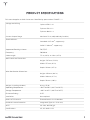
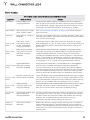
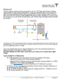
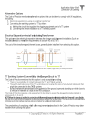
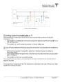
Tesla Gen 3 Wall Connector Manual (3PT2, UK) + Application Note provides guidelines for the installation and use of the Tesla Gen 3 Wall Connector. This manual includes important safety instructions that should be followed during installation, operation, and maintenance of the Wall Connector.
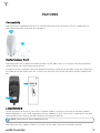
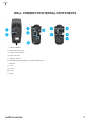
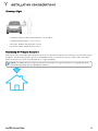
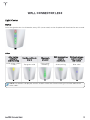
The Tesla Gen 3 Wall Connector is designed to charge electric vehicles. It can be used for both residential and commercial applications. The Wall Connector can be installed on a wall or a pedestal. It is weather-resistant and can be used both indoors and outdoors.
Tesla Gen 3 Wall Connector Manual (3PT2, UK) + Application Note
Tesla Gen 3 Wall Connector Manual (3PT2, UK) + Application Note provides guidelines for the installation and use of the Tesla Gen 3 Wall Connector. This manual includes important safety instructions that should be followed during installation, operation, and maintenance of the Wall Connector.
The Tesla Gen 3 Wall Connector is designed to charge electric vehicles. It can be used for both residential and commercial applications. The Wall Connector can be installed on a wall or a pedestal. It is weather-resistant and can be used both indoors and outdoors.


-
 1
1
-
 2
2
-
 3
3
-
 4
4
-
 5
5
-
 6
6
-
 7
7
-
 8
8
-
 9
9
-
 10
10
-
 11
11
-
 12
12
-
 13
13
-
 14
14
-
 15
15
-
 16
16
-
 17
17
-
 18
18
-
 19
19
-
 20
20
-
 21
21
-
 22
22
-
 23
23
-
 24
24
-
 25
25
-
 26
26
-
 27
27
-
 28
28
-
 29
29
-
 30
30
-
 31
31
-
 32
32
-
 33
33
-
 34
34
-
 35
35
-
 36
36
-
 37
37
-
 38
38
-
 39
39
-
 40
40
-
 41
41
-
 42
42
-
 43
43
-
 44
44


Tesla Gen 3 Wall Connector Manual (3PT2, UK) Owner's manual
- Type
- Owner's manual
- This manual is also suitable for
Tesla Gen 3 Wall Connector Manual (3PT2, UK) + Application Note
Tesla Gen 3 Wall Connector Manual (3PT2, UK) + Application Note provides guidelines for the installation and use of the Tesla Gen 3 Wall Connector. This manual includes important safety instructions that should be followed during installation, operation, and maintenance of the Wall Connector.
The Tesla Gen 3 Wall Connector is designed to charge electric vehicles. It can be used for both residential and commercial applications. The Wall Connector can be installed on a wall or a pedestal. It is weather-resistant and can be used both indoors and outdoors.
Ask a question and I''ll find the answer in the document
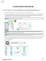
Finding information in a document is now easier with AI
Related papers
-
Tesla Gen 3 Wall Connector User manual
-
-
-
Tesla Mobile Connector Owner's manual
-
-
-
-
-
-
Other documents
-
 Zip-Ez zipez250 Installation guide
-
CPS SCA60KTL-DO/US-480 Operating instructions
-
-
doorKNOX VDP210 User guide
-
 LECTRON Tesla User manual
-
RIVIAN PT00057325 Wall Charger Installation guide
-
Faber OSTR30SS400 Owner's manual
-
-
-

