Page is loading ...

ba75434e04 03/2009
MPP 350
Operating manual
Multi parameter probe for pH, dissolved oxygen,
conductivity and temperature

MPP 350
32
ba75434e04 03/2009
Accuracy when
going to press
The use of advanced technology and the high quality standard of our
instruments are the result of continuous development. This may result in
differences between this operating manual and your instrument. Also, we
cannot guarantee that there are absolutely no errors in this manual.
Therefore, we are sure you will understand that we cannot accept any legal
claims resulting from the data, figures or descriptions.
Copyright
© Weilheim 2009, WTW GmbH
Reprinting - even as excerpts - is only allowed with the explicit written
authorization of WTW GmbH, Weilheim.
Printed in Germany.

MPP 350 Contents
33
ba75434e04 03/2009
MPP 350 - Contents
1 Overview . . . . . . . . . . . . . . . . . . . . . . . . . . . . . . . . . . . . . . . . . 34
1.1 Structure and function . . . . . . . . . . . . . . . . . . . . . . . . . . . . . . . 34
1.2 Instrument identification . . . . . . . . . . . . . . . . . . . . . . . . . . . . . 36
2 Safety . . . . . . . . . . . . . . . . . . . . . . . . . . . . . . . . . . . . . . . . . . . . 37
3 Commissioning . . . . . . . . . . . . . . . . . . . . . . . . . . . . . . . . . . . 37
3.1 Scopes of delivery . . . . . . . . . . . . . . . . . . . . . . . . . . . . . . . . . . 37
3.2 Getting the sensor ready for measuring . . . . . . . . . . . . . . . . . 39
4 Measuring / Operation . . . . . . . . . . . . . . . . . . . . . . . . . . . . . . 43
4.1 Calibration . . . . . . . . . . . . . . . . . . . . . . . . . . . . . . . . . . . . . . . . 43
4.2 Measuring . . . . . . . . . . . . . . . . . . . . . . . . . . . . . . . . . . . . . . . . 44
4.3 Storing . . . . . . . . . . . . . . . . . . . . . . . . . . . . . . . . . . . . . . . . . . . 44
5 Maintenance, cleaning, replacement . . . . . . . . . . . . . . . . . . 45
5.1 General maintenance instructions . . . . . . . . . . . . . . . . . . . . . . 45
5.2 Outside cleaning . . . . . . . . . . . . . . . . . . . . . . . . . . . . . . . . . . . 46
5.3 D.O. module: Changing the electrolyte solution and membrane
cap . . . . . . . . . . . . . . . . . . . . . . . . . . . . . . . . . . . . . . . . . . . . . . 47
5.4 D.O. module: Cleaning the electrodes . . . . . . . . . . . . . . . . . . 49
5.5 Checking the D.O. module for freedom from zero-current . . . 51
5.6 Aging of the probe . . . . . . . . . . . . . . . . . . . . . . . . . . . . . . . . . . 51
5.7 Disposal . . . . . . . . . . . . . . . . . . . . . . . . . . . . . . . . . . . . . . . . . . 52
6 What to do if... . . . . . . . . . . . . . . . . . . . . . . . . . . . . . . . . . . . . . 53
6.1 Error symptoms of D.O. measurement . . . . . . . . . . . . . . . . . . 53
6.2 Error symptoms of conductivity measurement . . . . . . . . . . . . 54
6.3 Error symptoms of pH measurement . . . . . . . . . . . . . . . . . . . 54
7 Technical data . . . . . . . . . . . . . . . . . . . . . . . . . . . . . . . . . . . . 55
7.1 Basic module with conductivity measuring cell . . . . . . . . . . . . 55
7.2 Dissolved oxygen (D.O.) module . . . . . . . . . . . . . . . . . . . . . . . 57
8 Wear parts and accessories . . . . . . . . . . . . . . . . . . . . . . . . . 60

Overview MPP 350
34
ba75434e04 03/2009
1Overview
1.1 Structure and function
The MPP 350 multi parameter probe is a modularly constructed sensor for
pH, dissolved oxygen, conductivity and temperature. Its maximum configura-
tion comprises the following basic components:
z Basic module with permanently built-in conductivity measuring cell ac-
cording to the quadripole measuring principle, with integrated temperature
sensor
z Removable dissolved oxygen module, according to the galvanic measur-
ing principle
z Removable, armored pH electrode with S7 plug-in connector
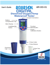
Detailed structure
(see figure on the
right page)
1 Closing head
2 Protective hood
3 Sinker
Conductivity measuring cell:
4 Temperature sensor in graphite enclosure
5 Voltage electrode (inside, 2x)
6 Current electrode (ring, 2x)
7 Plug connection for D.O. module
D.O. module:
8 Cap nut
9 Screw thread base with ventilation area
10 Lead counter electrode (anode)
11 Insulator
12 Gold working electrode (cathode)
13 Membrane cap (filled with electrolyte solution)
pH electrode:
14 S7 plug-in connector
15 Armoring
16 Sealing ring

MPP 350 Overview
35
ba75434e04 03/2009
1
2
14
15
16
3
4
5, 6
7
8
9
12
10
11
13
D. O. module
pH electrode
Conductivity measuring cell
Basic module

Overview MPP 350
36
ba75434e04 03/2009
The basic module is the basic component of the operable sensor. It can be
used as a stand-alone conductivity measuring cell with temperature sensor.
By mounting the D. O. module and/or pH electrode the basic module can be
extended to form a multi parameter probe for pH, dissolved oxygen, conduc-
tivity and temperature.
The D.O. module is connected to the basic module via a watertight, three-
pole plug connection. The conductivity measuring cell measures the temper-
ature, which is required for the determination of the D.O. content. For this
reason the D.O. module only works in conjunction with the basic module.
The pH electrode is electrically connected to the basic module via an S7 plug-
in connection. It is mechanically fixed with the aid of the protective hood.
Recommended
fields of
application
z On site measurements in rivers, lakes, sea water and brackish water as
well as waste water
z Measurements in boreholes (up to a diameter of two inches) up to 100 m
depth
z Fishfarming
z Measurements in ground water and spring water
z Applications in water laboratories
1.2 Instrument identification
A series number is printed on every module. Keep these numbers ready if
you have questions to ask the WTW service department.
The series numbers contain the following information:
Basic module The number is imprinted on the shaft of the conductivity measuring cell.
Dissolved oxygen
(D.O.) module
The number is imprinted on the cap nut.
pH electrode For notes concerning the series number of the electrode refer to the electrode
operating manual.
1 Manufacturing year 20... (example: 2004)
2 Calendar week of manufacturing (CW 36)
3 Sequential batch number (0013)
04360013
12 3
1 Manufacturing year 20... (example: 2004)
2 Calendar week of manufacturing (CW 42)
3 Sensor type (type A)
4 Sequential batch number (007)
0442A007
1234

MPP 350 Safety
37
ba75434e04 03/2009
2Safety
This operating manual contains special instructions that must be followed
during the operation of the sensor. Always keep this operating manual in the
vicinity of the sensor.
Special user
qualifications
The membrane cap of the D. O. module is filled with a small amount of an
alkaline electrolyte solution. All maintenance work that requires dealing with
the electrolyte solution must only be carried out by persons who know how to
deal with chemicals safely.
General safety
instructions
The individual chapters of this operating manual use safety labels like the one
below to indicate danger:
CAUTION
indicates instructions that must be followed precisely in order to avoid
slight injuries or damage to the instrument or the environment.
3 Commissioning
3.1 Scopes of delivery
3.1.1 Scope of delivery, MPP 350-x
z Basic module, with mounted D. O. module in the OxiCal
®
-MPP air calibra-
tion and storing vessel. The D.O. module is filled with electrolyte solution
and operable. The receptacle for the pH electrode is closed with a plug.
z MPP-Prot protective hood, mounted, with MPP-S sinker
z BR MPP 350 battery-powered stirrer (with cable lengths from 10 m only)
z Cable drum (with cable lengths from 40 m only)
z MPP-Cal calibration vessel for pH and conductivity
z ZBK 325 accessory set for D. O. module, comprising:
– 3 exchange membrane caps, WP 90
– Electrolyte solution, ELY/G
– Cleaning solution, RL/G
– Polishing strip, SF 300
z 1 closing cap for conductivity measuring cell
z 1 closing cap for D.O. module
z 1 plug for electrode receptacle
z Operating manual for MPP 350
z CD-ROM Update Multi 350i

Commissioning MPP 350
38
ba75434e04 03/2009
Note
The membrane cap that is mounted on the D.O. sensor for delivery serves
mainly as a transport protection. Depending on the duration of the transport
and storage period, it may have a shortened operational lifetime. If the mea-
suring system cannot be calibrated (error message on the instrument),
please proceed according to section 5.3 D.O.
MODULE: CHANGING THE ELEC-
TROLYTE SOLUTION AND MEMBRANE CAP.
3.1.2 Set equipment
The MPP 350 is also available as a set in the MPP-FC field case. You can
also buy the carrying case as an accessory and fit it with components your-
self. Electrodes with a cable length of up to 25 m fit in the carrying case. Or-
dering information, see chapter 8 W
EAR PARTS AND ACCESSORIES.
Equipment of the
field case
MPP-FC
(example)
1 Electrode or battery-powered
stirrer
8 Reagents (buffers etc...)
2 Manual, CD-ROM 9 Plug
3 Meter 10 Protective hood with sinker
4 Plug-in power supply unit 11 Exchange membrane caps
5 Small parts (adapters etc...) 12 Polishing film
6 MPP 350 with OxiCal
®
-MPP 13 pH/cond calibration vessel
1
2
4
5
67
8
9
10
13
11, 12
8
8
3

MPP 350 Commissioning
39
ba75434e04 03/2009
3.2 Getting the sensor ready for measuring
3.2.1 Measurements without D. O. module
Make sure that the plug connector of the conductivity measuring cell is tightly
closed with the suitable closing cap. When mounted, the closing cap (1) must
be screwed on up to the stop.
Before screwing on the closing cap, check the following points:
z The sealing (2) must be clean and evenly positioned in the groove.
z The plug connection and the inside of the closing cap must be clean and
dry.
3.2.2 Measurements without pH electrode
Make sure the electrode receptacle on the basic module (1) is tightly closed
with the plug (2) and the protective hood (4) is screwed on up to the stop. Be-
fore plugging in, check whether the sealing (3) of the plug is clean and cor-
rectly positioned. The sealing should always be slightly greased (with the O
ring grease of the pH electrode).
7 Connection cable
CAUTION
Never operate the MPP 350 without the protective
hood. The protective hood fixes the pH electrode or
plug in the electrode receptacle and guarantees a pres-
sure-resistant sealing. It especially protects the pH
electrode from mechanical damage.
1
2
3
2
4
1

Commissioning MPP 350
40
ba75434e04 03/2009
3.2.3 Mounting the D. O. module
Make sure that the D.O. module and conductivity measuring cell are screwed
together tightly. When mounted, the cap nut of the D.O. module has to be
screwed on up to the stop.
Before screwing on the D.O. module, check the following points:
z The sealing (3) must be clean and evenly positioned in the groove.
z The plug connection must be clean and dry on both sides.
Screwing on the
D.O. module
Position the D.O. module (1) on the conductivity measuring cell and carefully
and with slight pressure turn it until the guiding nib on the D.O. module locks
in place in the corresponding groove on the conductivity measuring cell.
Subsequently tighten the cap nut (2) up to the stop. The thread only snatches
if the D.O. module was correctly positioned.
Unscrewing and
storing the D. O.
module
Unscrew the cap nut and remove the D.O. module from the conductivity basic
module.
For storing, mount the clean and dry closing cap (4) on the D. O. module.
Thus the plug connection will remain optimally protected.
2
1
3
CAUTION
Inappropriate handling can lead to the release of elec-
trolyte solution. When unscrewing the D.O. module
only turn the cap nut (not the membrane cap!).
4

MPP 350 Commissioning
41
ba75434e04 03/2009
3.2.4 Mounting the pH electrode
Mount the electrode:
z If necessary, remove the plug from the electrode receptacle (1).
z Protect the pH electrode with the watering cap (4).
z Push the electrode (2) into the electrode receptacle up to the stop. When
doing so make sure the sealing (3) is clean and greased and correctly po-
sitioned in the groove.
z Remove the watering cap (4).
z Screw on the protective hood.
CAUTION
Never operate the MPP 350 without the protective
hood. The protective hood fixes the pH electrode or
plug in the electrode receptacle and guarantees a pres-
sure-resistant sealing. It especially protects the pH
electrode from mechanical damage.
Note
For further notes concerning the series number of the elec-
trode refer to the electrode operating manual.
2
3
1
5
4

Commissioning MPP 350
42
ba75434e04 03/2009
3.2.5 Plugging and unplugging the connection cable
First plug the main cable with the 8-pin plug in the instrument, then the pH
plug.
Always unplug the pH plug first, then the main cable with the 8-pin plug.
3.2.6 Preparing the measuring operation
Connect the sensor to the measuring instrument. The sensor is immediately
ready to measure. It is not necessary to polarize the D.O. module.
Note
For acclimatization before and after measuring and to protect the sensor from
external influences during periods of non-use we recommend to mount the
OxiCal
®
-MPP calibration and storing vessel equipped with a moist sponge on
the sensor.
CAUTION
For unplugging always grip the cable at the plug. Do
not pull at the cable or the branching, as the cable
could be torn off despite the built-in strain-relief.

MPP 350 Measuring / Operation
43
ba75434e04 03/2009
4 Measuring / Operation
4.1 Calibration
4.1.1 Calibrating for D. O. measurement
To calibrate the D.O. module, use the OxiCal
®
-MPP calibration and storage
vessel (white). It is screwed on the sensor instead of the protective hood.
Make sure that the sponge in the calibration vessel is always moist.
Moisten the sponge:
z Unscrew the lid (1).
z Take out the sponge (2) out of the lid, wet it, then slightly squeeze it out.
z Reinsert the sponge and close the calibration vessel with the cap.
Note
Please read the further course of the calibration in the operating manual of
the meter.
4.1.2 Calibrating for conductivity and pH measurement
To calibrate the conductivity measuring cell or pH electrode, use the MPP-
CAL calibration vessel (transparent). Fill the calibration vessel with enough
buffer solution or conductivity control standard so that the solution at least
reaches the marking groove (1) when the calibration vessel is screwed on.
Thus the temperature sensor is always immersed in the solution and
calibration can be carried out correctly.
Note
Depending on the number of modules mounted, different filling quantities are
required for the solution to reach up to the marking groove (1) (minimum
filling level) so that the temperature sensor is immersed in the measuring
solution.
Note
Please read the further course of the calibration in the operating manual of
the meter.
1
2
1

Measuring / Operation MPP 350
44
ba75434e04 03/2009
4.2 Measuring
Please always observe the required minimum immersion depth and the
minimum approach flow that is important for D.O. measurements (see
chapter 7 T
ECHNICAL DATA).
The minimum flow can be provided in different ways, e. g.:
z The flow of the water to be measured is sufficient (aeration tank, water
pipe, stream)
z Slowly pull the sensor through the water by hand (lake, container), or
z Use a flow aid, e. g. a magnetic stirrer or the battery-powered stirrer,
BR MPP 350. The battery-powered stirrer BR MPP 350 also serves as a
protective hood at the same time and is screwed on instead of the stan-
dard protective hood.
4.3 Storing
The sensor with the D.O. module must always be stored in the calibration
vessel. Make sure that the sponge in the calibration vessel is always moist.
Note
For further notes concerning the storing of the electrode refer to the electrode
operating manual.
CAUTION
If the BR 325 MPP is used in salt water (seawater, brack-
ish water), thoroughly rinse and clean with tapwater
(freshwater!) afterwards. Otherwise, corrosion damage
may occur.
Ein
On
Aus
Off
Battery-powered
stirrer,
BR MPP 350

MPP 350 Maintenance, cleaning, replacement
45
ba75434e04 03/2009
5 Maintenance, cleaning, replacement
5.1 General maintenance instructions
For your safety Note the following safety instructions when handling electrolyte and cleaning
solutions:
CAUTION
The ELY/G electrolyte solution and the RL/G cleaning solution irritate
the eyes and skin. Observe the following points when handling the so-
lutions:
z During working activities, always wear suitable protective gloves
and protective goggles/face shield.
z If it comes into contact with the skin, rinse thoroughly with water and
immediately change contaminated clothing.
z If it comes into contact with the eyes, rinse thoroughly with water
and consult a doctor.
z Follow the safety datasheets.
CAUTION
Before all maintenance activities, disconnect the sensor from the in-
strument.
Note
Information on how to order wear parts and maintenance equipment can be
found in chapter 8 W
EAR PARTS AND ACCESSORIES.
Maintenance
activities on the
D.O. module
For better handling, leave the D.O. module screwed on the conductivity
measuring cell. Thus, you can better immerse the sensor head in the
electrolyte or cleaning solution and the plug connection remains protected
against damage.

Maintenance, cleaning, replacement MPP 350
46
ba75434e04 03/2009
5.2 Outside cleaning
Basic module and
D.O. module
After cleaning, thoroughly rinse with deionized water and recalibrate if
necessary.
pH electrode For further notes concerning the cleaning of the electrode refer to the elec-
trode operating manual.
Contamination Cleaning procedure
Lime sediments Immerse in acetic acid (volume share =
10 %) for 1 minute
Fat/oil Clean with warm water that contains wash-
ing-up liquid

MPP 350 Maintenance, cleaning, replacement
47
ba75434e04 03/2009
5.3 D.O. module: Changing the electrolyte solution and mem-
brane cap
CAUTION
Before starting to work with the sensor, please note the GENERAL MAIN-
TENANCE INSTRUCTIONS on page 45.
General
information
WTW delivers the D.O. module ready to use (see section 3). The electrolyte
solution and membrane cap must only be replaced if:
z a calibration error occurs and the membrane is heavily contaminated
z the membrane is damaged
z the electrolyte solution is exhausted.
Changing the electrolyte solution and membrane cap
Unscrew the membrane cap.
Caution:
Electrolyte solution!
For disposal of the membrane
cap and electrolyte solution,
see section 5.7.
Rinse the sensor head with
deionized water.
Carefully rub and dry the
counter electrode with a lint-
free paper towel.
Immerse the sensor head in-
cluding the counter electrode
in RL/G cleaning solution.
Allow to react for 1 to 3 min-
utes.
Thoroughly rinse the sensor
head with deionized water.
Water the counter electrode in
deionized water for at least
10 minutes.
RL-G
H O
2

Maintenance, cleaning, replacement MPP 350
48
ba75434e04 03/2009
Carefully shake off the drops
of water.
Fill a new membrane cap with
ELY/G electrolyte solution.
Remove any air bubbles by
carefully tapping the mem-
brane cap. Additionally, you
can prevent air bubbles by
throwing the first filling away
and refilling the membrane
cap.
Thoroughly rinse the sensor
head with electrolyte solution.
Hold the sensor inclined and
screw on the membrane cap
fingertight using a paper tow-
el. Excess electrolyte solution
is forced out of the ventilation
area.
Check the filling:
Inspect the face surface. No
air bubbles may be present
within the dashed circle. Air
bubbles outside this area do
not interfere.
Note
For measurements under high pressure the filling must be com-
pletely free of air bubbles.
Readiness to measure The D.O. module is ready for operation after approx. 30 to 50 min-
utes. Subsequently calibrate the sensor for D.O. measurements.
Note
If you want to measure very low D.O. concentrations (< 0.5 % sat-
uration), we recommend to let the sensor rest overnight and then
calibrate it.
ELY/G
ELY/G
Ventilation area
points upwards
4 mm

MPP 350 Maintenance, cleaning, replacement
49
ba75434e04 03/2009
5.4 D.O. module: Cleaning the electrodes
CAUTION
Before starting to work with the sensor, please note the GENERAL MAIN-
TENANCE INSTRUCTIONS on page 45.
General
information
Cleaning is only required in cases of slopes too small or too large (sensor
cannot be calibrated) that cannot be resolved by changing the membrane cap
and electrolyte solution.
Cleaning the electrodes
Unscrew the membrane cap.
Caution:
Electrolyte solution!
For disposal of the membrane
cap and electrolyte solution,
see section 5.7.
Rinse the sensor head with
deionized water.
Using the rough side of the
wet SF 300 polishing strip,
polish off any contamination
from the gold working elec-
trode using light pressure.
Caution:
Do not use any con-
ventional sandpaper or glass-
fiber brushes.
Rinse the sensor head with
deionized water.
Wipe the counter electrode
with a lint-free paper towel
and carefully remove any
loose white deposits.
Immerse the sensor head in-
cluding the counter electrode
in RL/G cleaning solution.
Allow to react for 1 to 3 min-
utes.
SF 300
RL-G

Maintenance, cleaning, replacement MPP 350
50
ba75434e04 03/2009
Thoroughly rinse the sensor
head with deionized water.
Water the counter electrode in
deionized water for at least
10 minutes.
Carefully shake off the drops
of water.
Fill a new membrane cap with
ELY/G electrolyte solution.
Remove any air bubbles by
carefully tapping the mem-
brane cap. Additionally, you
can prevent air bubbles by
throwing the first filling away
and refilling the membrane
cap.
Rinse the sensor head with
electrolyte solution.
Hold the sensor inclined and
screw on the membrane cap
fingertight using a paper tow-
el. Excess electrolyte solution
is forced out of the ventilation
area.
Check the filling:
Inspect the face surface. No
air bubbles may be present
within the dashed circle. Air
bubbles outside this area do
not interfere.
H O
2
ELY/G
ELY/G
Ventilation area
points upwards
4 mm
/