Page is loading ...

85043073
Form P7618
Edition 1
April, 2003
OPERATION AND MAINTENANCE MANUAL
FOR IR90VR SERIES PAVING BREAKERS
IR90VR Series Paving Breakers are designed for general paving breaker work and demo-
lition and maintenance applications.
IMPORTANT SAFETY INFORMATION ENCLOSED - SAVE THESE INSTRUCTIONS
READ AND UNDERSTAND THIS MANUAL BEFORE OPERATING THIS PRODUCT
IT IS YOUR RESPONSIBILITY TO MAKE THIS SAFETY INFORMATION
AVAILABLE TO OTHERS THAT WILL OPERATE THIS PRODUCT
FAILURE TO OBSERVE THE FOLLOWING WARNINGS COULD RESULT IN INJURY
PLACING TOOL IN SERVICE
• Always install, operate, inspect and maintain this product
in accordance with all applicable standards and regula-
tions (local, state, country, federal, etc.).
• Always use clean, dry air at 90 psig (6.2 bar/620 kPa)
maximum air pressure at the inlet. Higher pressure may
result in hazardous situations including excessive speed,
rupture, or incorrect output torque or force.
• Be sure all hoses and fittings are the correct size and are
tightly secured. See Dwg. TP2125-1 diagram for a typical
piping arrangement.
• Ensure an accessible emergency shut off valve has been
installed in the air supply line, and make others aware of
its location.
• Do not use damaged, frayed or deteriorated air hoses and
fittings.
• Keep clear of whipping air hoses. Shut off the compressed
air before approaching a whipping hose.
• Always turn off the air supply, bleed the air pressure and
disconnect the air supply hose before installing, removing
or adjusting any accessory on this tool, or before perform-
ing any maintenance on this tool or any accessory.
• Do not lubricate tools with flammable or volatile liquids
such as kerosene, diesel or jet fuel. Use only recommended
lubricants.
• Use only proper cleaning solvents to clean parts. Use only
cleaning solvents which meet current safety and health
standards. Use cleaning solvents in a well ventilated area.
• Keep work area clean, uncluttered, ventilated and illumi-
nated.
• Do not remove any labels. Replace any damaged label.
USING THE TOOL
• Always wear eye protection when operating or
performing maintenance on this tool.
• Always wear hearing protection when operating this tool.
• Always use Personal Protective Equipment appropriate to
the tool used and material worked. This may include dust
mask or other breathing apparatus, safety glasses, ear
plugs, gloves, apron, safety shoes, hard hat and other
equipment.
• When wearing gloves always be sure that the gloves will
not prevent the throttle mechanism from being released.
• Prevent exposure and breathing of harmful dust and par-
ticles created by power tool use.
Some dust created by power sanding, sawing, grind-
ing, drilling, and other construction activities con-
tains chemicals known to cause cancer, birth defects
or other reproductive harm. Some examples of these
chemicals are:
- lead from lead based paints,
- crystalline silica from bricks and cement and
other masonry products, and
- arsenic and chromium from chemically treated
lumber.
Your risk from these exposures varies, depending on
how often you do this type of work. To reduce your
exposure to these chemicals: work in a well ventilated
area, and work with approved safety equipment, such
as those dust masks that are specially designed to fil-
ter out microscopic particles.
•
Keep others a safe distance from your work area, or ensure
they use appropriate Personal Protective Equipment.
• This tool is not designed for working in explosive environ-
ments, including those caused by fumes and dust, or near
flammable materials.
• This tool is not insulated against electric shock.
• Be aware of buried, hidden or other hazards in your work
environment. Do not contact or damage cords, conduits,
pipes or hoses that may contain electrical wires, explosive
gases or harmful liquids.
• Keep hands, loose clothing, long hair and jewelry away
from working end of tool.
Refer All Communications to the Nearest
Ingersoll-Rand Office or Distributor.
© Ingersoll-Rand Company 2003
Printed in Czech Republic
F
E
P

2
Using the Tool (Continued)
• Power tools can vibrate in use. Vibration, repetitive
motions or uncomfortable positions may be harmful to
your hands and arms. Stop using any tool if discomfort,
tingling feeling or pain occurs. Seek medical advice before
resuming use.
• Keep body stance balanced and firm. Do not overreach
when operating this tool. Anticipate and be alert for sud-
den changes in motion, reaction torques, or forces during
start up and operation.
• Tool and/or accessories may briefly continue their motion
after throttle is released.
• To avoid accidental starting - ensure tool is in “off” posi-
tion before applying air pressure, avoid throttle when car-
rying, and release throttle with loss of air.
• Do not carry or drag the tool by the hose.
• Do not use power tools when tired, or under the influence
of medication, drugs, or alcohol.
• Never use a damaged or malfunctioning tool or accessory.
• Do not modify the tool, safety devices, or accessories.
• Do not use this tool for purposes other than those recom-
mended.
• Use accessories recommended by Ingersoll-Rand.
• Do not use a quick disconnect coupling unless it is sepa-
rated from the tool by a whip hose. Attach whip hose to
tool using heavy duty, thick walled fitting.
• The inserted tool may break in use. Keep clear and main-
tain a balanced and firm stance.
• Always use appropriate retainer, latch or sleeve, in addi-
tion to proper barriers to protect persons in surrounding
or lower areas from possible ejected accessories.
• Never operate a Percussion Tool unless an accessory is
properly installed and the tool is held firmly against the
work.
• Attach safety cables across hose couplings and fittings and
install safety locking pins or clips on coupling to prevent
whipping air hoses.
• Only operate the throttle mechanism by hand. Keep hands
away from the throttle mechanism until it is time to oper-
ate the tool.
• Never rest the tool or chisel on your foot.
• Never point the tool at anyone.
• Do not touch the accessory or tool parts close to the acces-
sory immediately after operation. They may be hot and a
burn may result.
• Hold the tool firmly in both hands.
The use of other than genuine Ingersoll-Rand replacement parts may result in safety hazards, decreased tool
performance, and increased maintenance, and may invalidate all warranties.
Repairs should be made only by authorized trained personnel. Consult your nearest Ingersoll-Rand Authorized
Servicenter.
WARNING SYMBOL IDENTIFICATION
WARNING
Always wear eye protection
when operating or performing
maintenance on this tool.
WARNING
Read this manual before
operating tool.
WARNING
Always wear hearing
protection when operating
this tool.
Indicates compliance with
relevant CE directives.
European Community Mark
Sound Power Level

3
LUBRICATION
Rock Drill Oil
Always use an air line lubricator with these tools. We
recommend the following Lubricator-Unit and Lubricant:
In Line Lubricator: 6LUB12
Lubricant: Rock Drill Oil: 51378693
Attach the lubricator as close to the tool as practical.
After each two or three hours of operation and at the begin-
ning of each work shift, if an air line lubricator is not used,
disconnect the air hose and pour about 3 cc of oil into the air
inlet of the tool.
Before storing the tool or if the tool is to be idle for a period
exceeding twenty-four hours, pour about 3 cc of oil into the
air inlet and operate the tool for 5 seconds to coat the internal
parts with oil.
INSTALLATION
Air Supply and Connections:
Always use clean, dry lubricated air. Dust, corrosive fumes
and/or excessive moisture can ruin the motor of an air tool.
An air line filter can greatly increase the life of an air tool.
The filter removes dust and moisture.
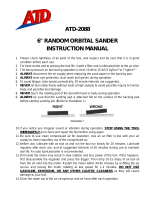
Make sure all hoses and fittings are the correct size and are
tightly secured. See diagram TP2125-1 for a typical piping
arrangement.
The tool is shipped from the factory with a custom thick
walled 3/4” NPT male inlet thread.
(Dwg. TP2125-1)
OPERATION
Accessory Installation:
Always turn off the air supply and disconnect the air
supply hose before installing, removing or adjusting
any accessory on this tool or before performing any
maintenance on this tool. Failure to do so could result
in injury.
For Latch Type Retainer
1. Operate the Latch until it is approximately 90 degrees to
the body of the tool and clicks into position.
2. Insert the accessory into the tool until the collar of the
accessory is past the Latch.
3. Operate the Latch until it is parallel to the tool and it
clicks into position.
30-40 lbs (15-20 kg) is the recommended amount of down-
force to apply to the tool when working.
The amount of downforce is correct when the tool hits rhyth-
mically, is comfortable to hold and works efficiently.
Do not operate the tool unless the chisel is against the work
since this will cause premature wear of parts and reduce the
vibration isolation properties of the tool.
Always break material to the point of “give.” Cracking does
not result in a complete break. Clear away rubble as it is
broken since uncleared rubble blocks the point of “give.”
Always take the right size “bite” with the tool. When work-
ing new material, experiment to find the right size “bite”
required for breaking that material efficiently.
If “bites” are too big, the operator will try to pry with
the tool. This could break the chisel. The tool is designed
for demolition, not prying. Always use a pick for prying.
If “bites” are too small, the operator will be working too
slowly.
If the chisel or accessory should become stuck, do not use
excessive force or mechanical means on the tool to pull out
the chisel. Doing so will damage the vibration isolation unit.
Break out the stuck chisel with a spare chisel or tool.
COMPRESSOR
MOTOR/COMPRESSOR
SHUT OFF
MAIN LINE & AIR
(EMERGENCY) SHUT OFF
3/4" ID AIR HOSE
IN-LINE OILER/LUBRICATOR
CONSTRUCTION TOOL

4
SPECIFICATIONS
■ Tested in accordance with ISO3744 and in compliance with Directive 2000/14/EC
♦ Tested in accordance with ISO8662
Note:
•
Specifications are given at 90 psig (6.2 bar/620 kPa), the recommended Maximum Working Pressure of the tool.
•
90 psig (6.2 bar/620 kPa) is the recommended Maximum Working Pressure at the inlet of the tool when it is operating.
•
103 psig (7.1 bar/710 kPa) is the Maximum Pressure at the inlet of the tool when it is not operating.
SAVE THESE INSTRUCTIONS. DO NOT DESTROY.
When the life of the tool has expired, it is recommended that the tool be disassembled,
degreased and parts be separated by material so that they can be recycled.
Model
Shank Size Hex
w/ Collar
Weight
Air
Consumption
Impacts
per min.
■ Certified Sound
Power Level
♦ Certified
Vibration Level
lbs (kg) CFM @ 90 psi dB (A) m/s
2
IR90VRA 1-1/8” x 6” 88 (40) 64 960 112 7.94
IR90VRB 1-1/4” x 6” 88 (40) 64 960 112 7.94

19
PART NUMBER FOR ORDERING PART NUMBER FOR ORDERING
1 Cylinder Assembly 15 TriggerPin ................................. 85040863
forIR90VRA ........................... 85043289 16 TriggerBall ................................ 85040871
forIR90VRB ........................... 85043271 17 TriggerSpring .............................. 85040889
2 Nozzle 18 InletBushing ............................... 85040897
forIR90VRA ........................... 85040574 26 HandleBodyScrew ............................. 85041036
forIR90VRB ........................... 85040590 27 HandleBodyNut ............................... 85041010
33 CushionBushing ............................ 85041150 28 SealingRing ................................... 85041044
FrontheadAssembly ............................ 85040665 29 Muffler ....................................... 85042497
3 Fronthead .................................. 85040673 30 SpacingWasher ................................ 85041069
6 Latch ..................................... 85040749 31 ValvePlate .................................... 85041093
20 Plunger .................................... 85040939 34 ValveRing .................................... 85041176
21 Plunger Spring .............................. 85040947 41 LatchKit ..................................... 85041317
22 FrontheadSpringPinInner .................... 85040962 6 Latch ..................................... 85040749
23 FrontheadSpringPinOuter.................... 85040988 20 Plunger .................................... 85040939
24 FrontheadScrew ............................ 85041002 21 Plunger Spring .............................. 85040947
25 FrontheadNut .............................. 85041028 22 FrontheadSpringPinInner .................... 85040962
4 Piston ........................................ 85042489 23 FrontheadSpringPinOuter.................... 85040988
HandleAssembly............................... 85040715 24 FrontheadScrew ............................ 85041002
5 HandleBody ............................... 85040723 25 FrontheadNut .............................. 85041028
7 Trigger .................................... 85040756
8 HandleLeverLeft ........................... 85040772
9 HandleLeverRight .......................... 85040798 * Nameplate .................................... 85040244
10 HandleGrip ................................ 85040806 * NameplateScrew............................... 85041325
11 HandleSpring .............................. 85040822 * NoiseLabel112 ................................ 85040236
12 HandlePivotPin ............................ 85040830 * WarningLabel ................................. WA RN I NG - - 6 - - 9 9
13 Sleeve..................................... 85040848 * InLineLubricator .............................. 6LUB12
14 HandleLeverStop ........................... 85040855 * RockDrillOil ................................. 51378693
* Not illustrated.

20
DISASSEMBLING THE IR90VR SERIES PAVING BREAKERS
GENERAL INSTRUCTIONS
• Do not repair the tool at the work site. Always take the
tool to a repair shop. Never drag the tool on the ground.
The air port and other openings will become clogged
with dirt and debris.
• Clean the breaker outer surface.
• Do not disassemble the breaker any further than
necessary to replace or repair damaged or worn parts.
• Whenever grasping a breaker or a part in a vice, always
use leather or copper-covered vice jaws to protect the
surface of the part and help prevent distortion. Take
extra care with threaded parts and housings.
• Do not remove any part that is a press fit in or on a sub-
assembly unless the removal of the part is necessary for
repairs or replacement.
• Do not disassemble the breaker unless a complete set of
O-rings is available for replacement.
DISASSEMBLY OF THE FRONT HEAD
Remove nut (25) and fronthead pinch bolt (24) from the
fronthead (3). Lightly tap the fronthead (using a hide mallet
if necessary) from the cylinder (1).
Press or drift out the two fronthead spring pins (22, 23) and
remove the latch (6).
The plunger (20) and the plunger spring (21) can be removed
from the fronthead.
HANDLE DISASSEMBLY
Using a hide mallet tap loose and remove the muffler (29)
from the cylinder.
Firmly grip the cylinder upright in a vice with leather or cop-
per covered jaws.
Loosen the four-handle nuts (27), unscrew and remove the
four-handle screws (26).
Lift the handle assembly (5) from the cylinder (1) (tap with a
hide mallet if necessary).
Press or tap out the handle pivot pin (12), remove both han-
dle levers (8 and 9) from the handle body (5) together with
the trigger (7). Tap out the sleeve (13) to detach the handle
levers from each other. Remove the handle springs (11)
from the handle body (5). If it is necessary to remove the
handle lever stop (14), use a punch of a suitable size Ø.60-
.75 in. (Ø15-19 mm) and drift the stop out from the
cylinder side.
Note: The Stop will be destroyed if removed.
It is possible to remove the trigger pin (15) at this stage if
required.
Unscrew the inlet bushing (18), and remove trigger spring
(17) the trigger ball (16) and throttle pin (15).
Remove the handle grips (10). It may prove easier to cut off
the old handle grips if they are to be replaced.
CYLINDER DISASSEMBLY
Remove the spacing washer (30) and valve plate (31). Slide
valve ring (34) from cylinder (1).
Remove sealing ring (28).
Release the cylinder from the vice, invert and allow the pis-
ton (4) to slide out and be caught.
The nozzle (2) is pressed in the cylinder and retained with
Loctite 601 – do not disassemble unless replacement is
necessary.

21
ASSEMBLY OF THE IR90VR SERIES PAVING BREAKERS
GENERAL INSTRUCTIONS
• Do not repair the tool at the work site. Always take the
tool to a repair shop. Never drag the tool on the ground.
The air port and other openings will become clogged
with dirt and debris.
• Before assembly of the breaker, clean all parts thor-
oughly and lubricate surfaces with a thin film of recom-
mended oil (see Lubrication).
• Apply a film of O-ring lubricant to all O-rings before
final assembly.
• It is recommended that the assembling of the nozzle (2)
should be carried out by the manufacturer or authorised
distributor.
• The existence of a piston air cushion should be deter-
mined. Hold the cylinder vertically and allow the piston
to drop down the bore small diameter first. An air cush-
ion is present if the piston “bounces” at the bottom of
the cylinder and no metal to metal contact noise can be
heard. If a cushion is not present contact your authorised
Ingersoll-Rand repair center for advice.
CYLINDER ASSEMBLY
Grip the cylinder (1) vertically in a vice protected with
leather or copper covered vice jaws.
Lubricate and insert the piston (4) small end first into the
bore. Check for cushion.
Lubricate and slide the valve ring (34) onto the cylinder (1)
and replace valve cover (31).
Position the valve spacer (30) on top of the valve cover (31).
Replace the sealing ring (28).
HANDLE ASSEMBLY
If the handle stop (14) was removed during disassembly it
should be replaced with a new part as the retaining feature
is severed on removal. Locate the stop in the hole in the han-
dle and tap sharply into place using a soft drift and hammer.
If the hand grip rubbers (10) have been removed these
should now be replaced. Lubricate the inside of the rubber
with soapy water and slide the new rubber into position.
Assemble left and right hand, hand grips (8 and 9), trigger
(7) together with sleeve (13), lubricate around the pivot area
and position the sub assembly along the slot in handle body
(5).
Note: It is usual to position the trigger lever on the same
side as the air inlet of the handle body.
Locate the handle springs (11) between hand grips and han-
dle body and fix the assembly in place by drifting or pressing
in handle pivot pin (12).
Lubricate the trigger pin (15), trigger ball (16) and replace
in the air inlet connection of the handle body.
Note: The trigger pin has a reduced diameter which is
placed next to the trigger ball.
Locate the trigger spring (17) on top of the trigger ball.
Apply thread retainer (loctite 243, or similar) on the thread
of the inlet bushing (18) and tighten to 147 lb. ft (200 Nm)
torque. Check that the handles and trigger move freely.
MAIN ASSEMBLY
Lightly grip the cylinder assembly vertically in a vice and
position the handle assembly in place.
Note: It is usual to orientate the trigger lever and air inlet
180 degrees from the fronthead bolt groove in the
cylinder.
Replace the four handle screws (26) use new handle nuts
(27) and tighten down evenly to a torque of 66.4 lb. ft
(90 Nm) torque.
Remove the cylinder and handle assembly from the vice.
Replace the muffler (29) on the assembly by tapping the
muffler fully home using a hide mallet.
FRONT HEAD ASSEMBLY
Apply a coating of grease then replace spring (21) and
plunger (20) in position in fronthead (3).
Position the latch (6) in its slot and secure in place by drift-
ing or pressing in outer spring pin (23). Position then press
or drift home inner spring pin (22).
Replace fronthead assembly onto cylinder and aligning
pinch bolt hole with the cylinder groove.
Replace pinch bolt (24) and nut (25) and tighten a torque of
147 lb. ft (200 Nm) torque.
ASSEMBLY CHECKS
Following service, the breaker should be checked for correct
operation prior to being released back to the job site.
Fit the correct size accessory into the breaker and connect to
an airline. Using air at low pressure 30 psi (2 bar), check
that the breaker is free from air leaks around the inlet con-
nection and that the breaker does not automatically start to
operate without the trigger being depressed.
Increase the air pressure to 90 psi (6 bar) and run the tool in
short bursts to check the tool operates correctly and stops
and starts cleanly without hesitation.
Breaker operating frequency should be 960 blows per minute
and air consumption 60 CFM (1.85m
3
/min) at 90 psi (6 bar)
air pressure.

Service Centers
Centres d’entretien
Centros de Servicio
Centros de Assistência Técnica
Ingersoll-Rand Company
510 Hester Drive
White House
TN 37188
USA
Tel: (615) 672 0321
Fax: (615) 672 0601
Ingersoll-Rand Sales Company Limited
Chorley New Road
Horwich, Bolton
Lancashire BL6 6JN
England - UK
Tel: (44) 204 880890
Fax: (44) 204 880388
Ingersoll-Rand Equipements de Production
111 Avenuè Roger Salengro
BP 59
F-59450 Sin Le Noble
France
Tel: (33) 27 93 0808
Fax: (33) 27 93 0800
Ingersoll-Rand GmbH
Gewerbealle 17
45478 Mülheim/Ruhr
Germany
Tel: (49) 208 9940
Fax: (49) 208 9994445
Ingersoll-Rand Italiana SpA
Casella Postale 1232
20100 Milano
Italy
Tel: (39) 2 950561
Fax: (39) 2 95380169
Ingersoll-Rand
Camino de Rejas 1, 2-18 B1S
28820 Coslada
Spain
Tel: (34) 1 669 5850
Fax: (34) 1 669 6054
Ingersoll-Rand Nederfand
Produktieweg 10
2382 PB Zoeterwoude
Netherlands
Tel: (31) 71 45220
Fax: (31) 71 218671
Ingersoll-Rand Company SA
PO Box 3720
Alrode 1451
South Africa
Tel: (27) 11 864 3930
Fax: (27) 11 864 3954
Ingersoll-Rand
Scandinavian Operations
Kastruplundgade 221
DK-2770 Kastrup
Denmark
Tel: (45) 32 526092
Fax: (45) 32 529092
Ingersoll-Rand SA
The Alpha Building
Route des Arsenaux 9
CH-1700 Fribourg
Switzerland
Tel: (41) 37 205111
Fax: (41) 37 222932
Ingersoll-Rand Company
Presnensky Val
19, Moscow, Russia 123557
Tel: (7) 095-933-03-24
Fax: (7) 095-737-01-48
Ingersoll-Rand Company
16 Pietro
Ul Stawki 2
PL-00193 Warsaw
Poland
Tel: (48) 2 635 7245
Fax: (48) 2 635 7332
0403
/