CWT-00
C1100
Chilled Water Tank & Cold Only Faucet
Owner’s Manual
Installation, Care & Use
Instalacion, cuidado & uso

Equipment You May Need:
IMPORTANT: After unpacking chilled water tank, place the unit upright for 1 hour before
connecting power.
For best results, the cold water faucet should be installed prior to installing the chilled water tank.
For your satisfaction and safety, read all instructions, cautions, warnings and dangers before installing or
using this chilled water tank.
This particular unit is not intended for commercial use.
Make sure that all electrical wiring and connections conform to local codes.
A standard 120-volt grounded electrical outlet is required under the sink for the chilled water tank’s electrical power.
It is recommended that a separate circuit providing power only to the chilled water tank be used.
The wall outlet powering the chilled water tank must be fused and should not be controlled by the same wall
switch used by the food waste disposer.
It is recommended that a dedicated control valve be installed on the cold water line supplying water to this
system. Make sure all water supply control valves do not have a backflow preventer in them.
If you suspect elevated levels of chlorine in your water, it is recommended to use our water filtration system.
The water pressure to the chilled water tank should be between a minimum of 30 psi (207kPa) and
a maximum of 100 psi (689kPa).
The chilled water tank may cause an increase in temperature in your cabinet when running.
The chilled water tank has a refrigeration compressor, which may generate noise while running.
The chilled water tank should only be installed in an upright position.
The chilled water tank is intended only for chilling water.
WHAT YOU SHOULD KNOW BEFORE YOU BEGIN
Equipment Required: (sold separately)
Cold water faucet
T-fitting
Dedicated control valve
Adjustable wrench
Utility knife
Tape measure / ruler
If you will be installing a dedicated cold only water faucet and intend to use the sprayer hole in your sink
for that faucet, you may need a basin wrench and a 1/8" plug or a 1/4" hose line cap (not supplied).
If you need to cut a mounting hole in your stainless steel sink, you may need a 1
1
⁄4" - 1
1
⁄2" hole saw made
for cutting stainless steel or a hole punch. Consult a professional if you are drilling into a surface other
than stainless steel.
WHAT YOU NEED TO GET STARTED
Hole saw / hole punch
Basin wrench
Congratulations on your purchase of this quality InSinkErator
®
water product. In addition
to complete operating and care instructions, in this Owner’s Manual you will find instructions
for installing both:
• CWT-00 Chilled Water Tank with an existing hot/cool water dispenser – See pages 4-6
• CWT-00 Chilled Water Tank with a C1100 Cold Only Faucet – See pages 7-9
2

HOW TO USE THIS INSTRUCTION MANUAL
These instructions are separated into main sections, indicated by numbers, and subsections,
indicated by capital letters. The manual is setup this way to allow you to take a break at any
point after completing a section or subsection without affecting the installation process.
What you’ll see in the
instruction manual:
Property Damage: Do not pinch or break tubing.
Do not distort the last 1 inch of tubing.
B
Attach
s
upplied quick connect elbow to
end of supplied blue 1/4" tube.
Attach
quick connect elbow with
blue tube
to water Outlet on front
of chilled water tank.
Measure distance from tank outlet to
water supply line on faucet
. Carefully
trim blue tube to correct length.
Using quick connect elbow, connect
blue tube to faucet water supply.
Outlet
1
2
3
Provides a step-by-step narrative describing the installation step, with check boxes that
can be marked as you progress through the installation.
Contains simple illustrations that provide visual instruction to support the narrative.
CAUTIONS, WARNINGS and DANGERS that will require your attention during the step.
1
2
3
An imminently hazardous situation, which, if not avoided, will result in death or serious injury.
A potentially hazardous situation, which, if not avoided, could result in death or serious injury.
A potentially hazardous situation, which, if not avoided, may result in minor or moderate injury.
PACKAGE COMPONENTS
Chilled Water TankQuick Connect Elbows (3)
White Tubing - 4'
Blue Tubing - 4'
Cold Only Faucet
Rubber O-Ring
Hex Nut
Semi-circular Mounting Plate
Hex Tool
CWT-00 C1100
“Y” Quick Connector
3

Property Damage: Do not place objects
on top of chilled water tank which
could obstruct the fan.
PREPARATION
Unplug instant hot water tank and
hold handle in open position until
cool water flows from spout.
Turn off water supply.
Identify the undersink location for the
chilled water tank.
For best performance, allow for a
minimum 2
"
space around the sides
and top of the chilled water tank.
The chilled water tank will require
a minimum footprint of 15
"
wide
by 11
"
deep.
Ensure that there is a minimum of 18
"
vertical clearance for the chilled water tank.
1
A
< 18"
< 11"
< 15"
Follow these steps for installing chilled water tank with instant hot/cool water dispenser.
Blue Tubing
White Tubing
Instant Hot/Cool
Water Dispenser Faucet
Filter
Instant
Hot Water
Tank
Food
Waste
Disposer
Chilled
Water
Tank
Air-Activated
SinkTop Switch
™
Copper Tubing
Shown with optional filtration
OVERVIEW OF A TYPICAL INSTALLATION with Instant Hot Water Dispenser
These instructions assume hot/cool faucet has already been installed. Refer
to Installation, Care & Use manual included with hot/cool water dispenser.
4
Note: Chilled water tank must be plugged
directly into open wall outlet.

A
B
A
B
Property Damage: Join remaining tube
to cold water supply only. Water supply
valves must not prevent backward flow.
3
Install a T-fitting (not included)
onto the cold water supply line.
Install dedicated water control valve
with 3/8" compression fitting.
Install brass nut, ferrule and tube insert
on to white 3/8" tube which runs from
filter or “Y” quick-connect fitting.
Insert the white 3/8" tube into the 3/8"
compression fitting and tighten.
WATER CONNECTION
Brass Nut
Ferrule
Brass Insert
From filter or
water supply
White Tape
From filter or
water supply
To chilled water
tank “Inlet”
To hot water
dispenser
To remove tube(s) or plug from quick-connector,
depress the release ring and gently pull away.
Follow these steps for installing chilled water tank with instant hot/cool water dispenser.
Property Damage: All tubes must be cut
squarely with no burrs.
2
Attach
s
upplied quick connect elbow to
end of supplied white 1/4" tube.
Attach
quick connect elbow
to water
Inlet on front of chilled water tank.
Measure distance from water inlet on
chilled water tank to water supply valve
(See Step 3)
. Carefully trim white 1/4"
tube, allowing ample slack in tubing.
INSTALLING THE WATER TANK
Attach
s
upplied quick connect elbow to
end of supplied blue 1/4" tube.
Attach
quick connect elbow with blue
tube
to water Outlet on front of chilled
water tank.
Measure distance from the chilled
water tank outlet to water supply line
on faucet. Carefully trim blue tube to
correct length.
Using quick connect elbow, connect
remaining end of blue tube to unmarked
copper tube coming from faucet.
White Tape
Inlet
Property Damage: Do not pinch or break tubing.
Do not distort the last 1 inch of tubing.
Pull on connection to ensure fully engaged.
Remove existing “Y” quick-connect
fitting and discard.
Connect white 3/8" tube from the
filter or water supply into the supplied
“Y” quick-connect fitting until it stops.
Insert 1/4" white tube from tank inlet
into the 3/8" to 1/4" quick-connect fitting.
Identify copper HOT water tube,
which is marked with white tape.
Install that tube into the 3/8" to 1/4"
quick-connect fitting.
5
Outlet

A
B
Follow these steps for installing chilled water tank with instant hot/cool water dispenser.
Property Damage: Before plugging in
chilled water tank, check for leaks in all
water supply connections.
Turn on the cold water supply.
Depress the cold faucet handle
and hold it until water flows from
the spout.
Allow water to run for at least
60 seconds after water begins to
flow from faucet.
Depress the hot water handle until
water flows smoothly.
4
FILL TANK & CONNECT POWER
Check all connections to ensure they
are tight and that there are no leaks.
Plug in chilled water tank
and hot water dipenser tank.
Prior to drinking water from the chilled
water tank, run the water for at least 5
minutes to flush lines.
Allow up to 60 minutes for
water to reach target temperature.
Property Damage: A standard grounded
outlet is required under the sink.
Do not use an extension cord set with
the chilled water tank.
6
Gurgling or hissing is normal
during the initial heating cycle.
The SinkTop Switch
™
from InSinkErator
®
conveniently switches power between two
electrical outlets, which allows the chilled water tank, hot water dispenser and food
waste disposer to be connected to the same electrical outlet. The chilled water tank
should not be plugged into the SinkTop Switch. The chilled water tank must be connected
directly into the open wall outlet. For more information visit www.insinkerator.com.

A
Property Damage: Do not place objects
on top of chilled water tank which
could obstruct the fan.
PREPARATION
Turn off water supply.
Identify the undersink location for the
chilled water tank.
For best performance, allow for a
minimum 2
"
space around the sides
and top of the chilled water tank.
The chilled water tank will require
a minimum footprint of 15
"
wide
by 11
"
deep.
Ensure that there is a minimum of 18
"
vertical clearance for the chilled water tank.
1
Filter
Copper Tubing
Blue Tubing
White Tubing
Cold Only Faucet
Food
Waste
Disposer
Air-Activated
SinkTop Switch
™
Chilled
Water
Tank
Shown with optional filtration
OVERVIEW OF A TYPICAL INSTALLATION with Cold Only Faucet
Follow these steps for installing chilled water tank with a cold only faucet.
InSinkErator C1100
Cold Only Faucet
The instructions on pages 7-9 will guide you through the
installation of the InSinkErator C1100 Cold Only Faucet
and your Chilled Water Tank.
7
< 18"
< 11"
< 15"

A
B
B
A
Property Damage: Do not pinch or break copper
tubing. Do not distort the last 1 inch of tubing.
2
An assistant may be needed to hold
the faucet in place
while securing the base.
INSTALLING THE COLD ONLY FAUCET
Follow these steps for installing chilled water tank with a cold only faucet.
Feed tube down through sink hole
until the base is at rest.
From under the sink, place the
semi-circular mounting plate onto
the threaded stud.
Place hex nut onto the threaded stud.
Ensure faucet is at desired angle.
Insert screwdriver into hole on side of
hex tool (creating a “T”), and use tool
to tighten nut and secure faucet.
Unpack faucet components.
On a firm, flat surface, carefully
straighten the copper tubing.
Ensure that the black O-ring is
properly seated in the base of the
faucet (the groove on the underside
of the faucet base).
Property Damage: Do not pinch or break tubing.
Do not distort the last 1 inch of tubing.
Pull on connection to ensure fully engaged.
Attach
s
upplied quick connect elbow to
end of supplied blue 1/4" tube.
Attach
quick connect elbow with blue
tube
to water Outlet on front of chilled
water tank.
Measure distance from chilled water tank
outlet to water supply line on faucet
.
Carefully trim blue tube to correct length.
Using quick connect elbow, connect
blue tube to faucet water supply.
Property Damage: All tubes must be cut
squarely with no burrs.
3
Attach
s
upplied quick connect elbow to
end of supplied white 1/4" tube.
Attach
quick connect elbow
to water
Inlet on front of chilled water tank.
Measure distance from water inlet on
chilled water tank to water supply
valve (See Step 3)
. Carefully trim white
1/4" tube, allowing ample slack in tubing.
INSTALLING THE WATER TANK
8
Inlet
Inlet

A
A
B
Follow these steps for installing chilled water tank with a cold only faucet.
Property Damage: Join remaining tube
to cold water supply only. Water supply valves
must not prevent backward flow.
4
Install a T-fitting (not included)
onto the cold water supply line.
Install dedicated water control valve
with 1/4" compression fitting.
Attach remaining end of the supplied
white 1/4" tube into the 1/4"
compression fitting and tighten.
With no filtration system:
WATER CONNECTION
Property Damage: Join remaining tube
to cold water supply only. Water supply valves
must not prevent backwards flow.
A
Brass Nut
Ferrule
Brass Inse
For filtration installation instructions, see
installation guide packed with the system.
Install a T-fitting (not included)
onto the cold water supply line.
Install dedicated water control valve
with 3/8" compression fitting.
Install brass nut, ferrule and tube insert at
the end of the white 3/8" tube from filter.
Insert the white 3/8" tube into the 3/8"
compression fitting and tighten.
With optional InSinkErator filtration system:
To “Inlet” on front of
chilled water tank
Property Damage: Before plugging in
chilled water tank, check for leaks in all
water supply connections.
Turn on the cold water supply.
Depress the faucet handle and
hold it until water flows from the
spout.
Allow water to run for at least 60
seconds after water begins to flow
from faucet.
5
FILL TANK & CONNECT POWER
Check all connections to ensure they
are tight and that there are no leaks.
Plug in chilled water tank.
Prior to drinking water from the
chilled water tank, run the water for
at least 5 minutes to flush lines.
Allow up to 60 minutes for
water to reach target temperature.
Property Damage: A standard grounded outlet
is required under the sink. Do not use an
extension cord set with the chilled water tank.
9

Electric Shock Hazard: Using an ungrounded or improperly connected
appliance can result in serious injury or death from electrical shock.
Property Damage: To avoid water damage, replace any loose or split tubing.
Periodically inspect the unit for any signs of leakage and immediately remove from
service any unit suspected of leaking.
CWT-00 Tank: 3-year warranty
C1100 Faucet: 5-year warranty
Covers all replacement parts and labor to correct defects in material or workmanship in the
chilled water system, excluding the replaceable filter cartridge, for the full warranty period from
the date of installation in your home. If warranty service is required during the warranty period,
contact an authorized InSinkErator service agent to replace or repair the unit in your home at
no cost to you. If your chilled water system is replaced rather than repaired, the warranty on
the new unit shall be for the duration of the remaining portion of the original system’s warranty.
Note: Warranty is determined by unit serial number and/or date of installation. Purchase or
installation receipt may be required to verify warranty status. When service is required, and for
the location of your nearest factory authorized service center, call toll free 1-800-558-5700.
The foregoing warranty does not apply to damage or inoperation resulting from accident,
alteration, misuse, abuse, improper installation, installation not in accordance with these
instructions or local electrical and/or plumbing codes. We do not assume any responsibility for
consequential damage. Install using genuine InSinkErator
®
manufactured components only.
Use of non InSinkErator components will void your warranty.
Some states do not allow limitations on how long an implied warranty lasts, or the
exclusion or limitations of incidental or consequential damages, so the above limitations or
exclusion may not apply to you. This warranty gives you specific legal rights, and you may
also have other rights which vary from state to state.
This appliance must be grounded. This chilled water system is equipped with a cord that has a
grounding conductor and a grounding pin. The plug must be connected to an appropriate outlet that
is properly installed and grounded in accordance with all local codes and ordinances.
Do not modify the plug provided with the appliance – if it will not fit the outlet, have a proper outlet
installed by a qualified electrician. Check with a qualified electrician or serviceman if you are in
doubt as to whether the chilled water system is properly grounded.
WARRANTY INFORMATION
Electrical Shock Hazard: Plug unit into a grounded, 3-prong outlet. Do not remove
ground plug. Do not use an adapter. Failure to follow these instructions can result in
death, fire and/or electrical shock.
IMPORTANT: Observe all plumbing/electrical codes and ordinances.
Check location in which the chilled water tank will be installed to ensure there
is adequate space. Proper installation is the responsibility of the installer.
Before beginning installation, ensure that you have all required parts. It is the
responsibility of the installer to comply with installation specifications and with
state and local plumbing codes.
10

Electric Shock Hazard: To prevent electrical shock, disconnect power before
servicing unit. Use only a properly grounded and polarized electric outlet.
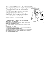
Replace filter cartridge when there is an obvious
decrease in water flow to the faucet or if there is an
objectionable taste or odor to the water.
When the inlet and outlet ports have been closed
and the filter’s internal pressure has been relieved,
water (about 2 oz) will discharge from vent line.
If the new filter cartridge cannot be inserted,
insert the old one and turn until it stops, remove it
and then retry the new cartridge.
Carbon filters should be replaced within 12 months.
Filter replacement instructions:
Replace with an InSinkErator
®
filter.
Place pan or dish towel under the filter to
catch water drainage during change.
Slowly turn the cartridge counter-clockwise
completely until it stops (1/4 turn).
Pull cartridge straight down and discard.
Insert new cartridge into filter head.
Top surface of cartridge will become flush
with the bottom of the filter head when
fully engaged.
Turn the cartridge clockwise until it stops
(1/4 turn).
Align the in/out arrow on the head and
bracket assembly to the in/out arrow on
the cartridge.
Open faucet to expel trapped air.
Run water for 3 minutes before usage.
The temperature on the chilled
water tank is controlled by the
temperature control knob
on the front of the unit.
For colder water –
Turn the control knob
clockwise. Allow 60 mins.
For less cold water –
Turn the control knob counterclockwise.
To shut down the chilled water tank –
Turn control knob counterclockwise
to the “OFF” position.
Regularly inspect the unit for any signs of
leakage. If there are signs of water damage,
immediately remove the unit from service.
To avoid water damage from leakage,
replace all cut, loose or split tubing.
A drain pan, plumbed to an appropriate
drain or outfitted with a leak detector,
should be used in those applications where
any leakage could cause property damage.
PROPERTY DAMAGE
CARE AND USE
Only use mild cleaners to clean the faucet
and plastic components.
Cleaners with acids, abrasives, alkaline or
organic solvents will result in deterioration of
the plastic components and void the warranty.
CLEANING THE TANK AND FAUCET
Anytime the chilled water tank will not be used for an
extended period, or if temperature is below freezing,
unplug and drain the unit.
Disconnect power from unit.
Shut the cold water supply off at the valve.
Open cold only faucet to relieve pressure
from the chilled water tank.
Disconnect the inlet/outlet water lines
attached to the chilled water tank.
Drain water from the chilled water tank by
tipping it on its left side (power cord side)
and allow water to run into a large container.
Once drained, set unit in its normal
upright position for storage.
To put the chilled water tank back into
service, reconnect the water lines (see
Pages 4-7) and open the water supply.
Open the cold water faucet until water
runs from the faucet.
Plug in the unit and set control knob to
desired temperature.
SEASONAL STORAGE/DRAINAGE
FILTER GUIDE AND REPLACEMENT
(Filtration available as an option)
ADJUSTING WATER TEMPERATURE
C
o
l
d
e
r
w
a
t
e
r
11

WHAT TO DO
Water is not cold. • No power to unit.
• The unit is unplugged.
• The electric outlet is inoperative.
• Copper tubes connected incorrectly.
• The unit has not had sufficient time to
chill the water.
• Make sure the circuit breaker or fuses are
functioning properly.
•
Make sure the unit is connected to a properly grounded
electric outlet.
• Check that the outlet is not switched off.
• Switch copper tube connections.
• Cold water in the chilled water tank is still being chilled.
Wait 15 minutes and check temperature once again.
• Check that the temperature control knob is set to the
maximum cold setting.
• Tube is blocked. •
Check that tubes are not kinked, twisted or pinched.
•
Unscrew spout end piece and clean out any debris.
Cold water drips or
sputters from spout.
• Insufficient water supply
• The spout is blocked.
• Check the supply valve to ensure that is fully open and
there are no obstructions in the water line reducing the
pressure below 30 psi (
i.e., a poorly mounted saddle
valve, a clogged water filter, or a partially opened
shut-off valve).
• Check to see if chilled water tank is improperly connected
to hot water supply line. If so, attach to cold water line.
•
Unscrew spout end piece and clean out any debris.
Water does not flow
from spout.
Water is dripping
from the spout/vent
constantly.
• Debris in the water line may be
in the faucet valve seat causing a
slow water leak.
•
Unscrew spout end piece and clean out any debris.
•
Activate faucet lever 7-10 times to flush faucet & lines.
Divided stream.
• Debris in the end piece. •
Unscrew spout end piece and clean out any debris.
Unpleasant taste.
• Chilled water tank requires purging. •
If chilled water has not been dispensed for 3 or more days, or
if fewer than 3 cups per day are dispensed, the chilled water tank
should be purged. Run cold only faucet for 3 minutes to purge
chilled water tank. Wait 1 hour before dispensing fresh water.
PROBLEM POSSIBLE CAUSE
Please read Troubleshooting Guide and/or visit
www.insinkerator.com before calling AnswerLine
™
TROUBLESHOOTING
12
FILTRATION ISSUES
(Filtration available as an option)
Water taste or odor
New filter leaks or
doesn’t fit
No water flow or
low water flow
• Filter needs to be flushed out
• Life of filter has expired
• Head and bracket not fully rotated
• Filter O-ring breach
• Life of filter has expired
• Activate the faucet lever and run until the water is cold.
If there is no change, replace filter cartridge.
• Remove, inspect, reinstall filter cartridge.
• Remove new filter, replace with old filter. Check operation.
If OK, reinstall new filter and recheck operation.
• Replace filter cartridge. See page 11.
Page is loading ...
Page is loading ...
Page is loading ...
Page is loading ...
Page is loading ...
Page is loading ...
Page is loading ...
Page is loading ...
Page is loading ...
Page is loading ...
Page is loading ...

The Emerson logo is a trademark and
service mark of Emerson Electric Co.
InSinkErator may make improvements and/or
changes in the specifications at any time, in its sole
discretion, without notice or obligation and further
reserves the right to change or discontinue models.
1.800.558.5700
www.insinkerator.com
© 2008 InSinkErator, a division of
44149 REV. A Printed in USA Emerson Electric Co. All Rights Reserved.
/