Page is loading ...

48313 48313 48313 48313
IMPORTANT DOCUMENTS ENCLOSED
CAUTION:
To reduce the risk of injury due to hot water
burns, make sure the enclosed labels are
applied where specified on the label.
DOCUMENTOS IMPORTANTES INCLUIDOS
AVISO:
Para reducir el riesgo de lesión por
quemaduras de agua caliente, asegúrese que
las etiquetas incluidas se han aplicado donde
se ha especificado en la etiqueta.
DOCUMENTS IMPORTANTS À L’INTÉRIEUR
MISE EN GARDE :
Pour réduire le risque d’ébouillantage, veuillez
apposer les étiquettes fournies aux endroits
indiqués sur celles-ci.
48313 48313 48313 48313

11/12/08 48313 Rev D
NOTICE TO INSTALLER: Place this label on the water heater next
to the temperature adjustment knob.
WARNING:
These series of tub/shower valves do not adjust automatically
for changes in temperature at the hot water heater or inlet. If the
temperature setting of the hot water heater or inlet is changed, the setting
on these valves must be adjusted manually! Failure to re-adjust the valve
may result in hot water burns or extreme cold resulting from variations in
line pressure (such as when a dishwasher or washing machine is in use
while you are taking a shower). After installation, verify that the rotational
limit stop (18 series) or temperature knob (18T series) on the valve
is set so that changes in line pressure or temperature do not result in
uncomfortable water temperature changes. If the temperature setting of
the hot water heater or inlet is changed after installation of the valve,
the setting of the rotational limit stop or temperature knob also must
be changed! Consult the installation instruction sheet for instructions on
how to make this setting, or call us at 1-800-345-DELTA.
AVISO AL INSTALADOR: Coloque esta etiqueta en el calentador
de agua al lado de la perilla para el ajuste de temperatura.
AVISO:
Esta serie de válvulas para bañeras/regaderas no se ajustan automáti-
camente a los cambios de temperatura en el calentador de agua o en
el agua de entrada. Si el ajuste de la temperatura del calentador de agua
o la temperatura del agua que entra cambia ¡El ajuste de estas válvulas
se debe hacer manualmente! El no reajustar la válvula puede resultar en
quemaduras por agua caliente o temperaturas de agua extremadamente
frías resultando en variaciones de presión y temperatura (como cuando el
fregador de platos o la lavadora están funcionando mientras que se baña).
Después de la instalación, verifique que el control o tope del límite rotacional
(Series 18) o la perilla del control de temperatura (Series 18T) en la válvula
está ajustada para que los cambios de presión y de temperatura en la línea
no resulten en cambios incómodos de temperatura del agua. Si el ajuste de
la temperatura del calentador de agua o de la entrada de agua se cam-
bia después de la instalación de la válvula, el ajuste del tope del límite
rotacional o la perilla de ajuste ¡también se debe cambiar! Consulte con
su hoja de instrucciones de instalación para saber como se ajusta o cambia
el ajuste, o llámenos al 1-800-345-DELTA.
AVIS À L’INSTALLATEUR: Fixez cette étiquette sur le chauffe-eau
près du bouton de réglage de température.
ATTENTION :
La soupape de robinet de baignoire ou de douche de cette série ne se
règle pas automatiquement en fonction des changements de température
de l’eau chaude au chauffe-eau ou de l’eau d’alimentation. En cas de
modification du réglage de température du chauffe-eau ou de la température
de l’eau d’alimentation, le réglage de cette soupape doit être modifié
manuellement! Si le réglage de la soupape n’est pas modifié, le robinet pourra
permettre l’écoulement d’eau très chaude susceptible de causer l’ébouillantage
ou d’eau très froide, sous l’effet des variations de pression et de température
dans la tuyauterie d’alimentation (lorsque la douche est utilisée en même temps
que le lave-vaisselle ou la machine à laver, par exemple). Après l’installation,
assurez-vous que la butée de température maximale (séries 18) ou le bouton
de température (séries 18T) sur la soupape est réglé de manière que les
fluctuations de pression et de température dans la tuyauterie d’alimentation
n’entraînent pas de changements de température de l’eau inconfortables. En
cas de modification du réglage de température du chauffe-eau ou de la
température de l’eau d’alimentation après l’installation de la soupape, le
réglage de la butée de température maximale ou du bouton de température
doit être modifié! Pour régler le bouton de température, consultez la feuille
d’instructions d’installation ou appelez-nous au 1-800-345-DELTA.
11/12/08 48313 Rev D
BY/POR/PAR _______________ COMPANY/COMPANIA/COMPAGNIE ________________
DATE/FECHA/LE ___________ PHONE/TELÉFONO/TELÉPHONE ____________________
NOTICE TO INSTALLER: Place this label close to the valve where the owner
will see it, such as inside the door of a cabinet or vanity.
WARNING:
Water temperature changes due to seasonal or other inlet variations, such as changing the
setting on the hot water heater may require adjustment of the rotational limit stop (18 Series) or
temperature knob (18T Series) on your tub/shower valve to ensure a safe maximum temperature.
These valve series do not automatically adjust for inlet temperature changes. If changes occur and
you are not sure how to make the necessary rotational limit stop or temperature knob adjustments,
please consult the installation instruction sheet provided with this valve or call 1-800-345-DELTA.
These valve series are designed to minimize the effects of outlet water temperature changes
due to inlet pressure changes, commonly caused by dishwashers, washing machines, toilets and
the like. They may not provide protection from hot water burns when there is a failure of
other temperature controlling devices elsewhere in the plumbing system. After making the
necessary adjustments please fill in the information below. This valve/system has been set by the
person listed below to ensure a safe maximum temperature. Any change in the setting may raise
the discharge temperature above the limit considered safe and could lead to hot water burns. If
this label has not been completed, you should verify that the rotational limit stop or temperature
knob has been properly adjusted to suit your individual installation. The installation instruction sheet
supplied with the valve provides information on how to make this setting.
AVISO AL INSTALADOR: Coloque esta etiqueta cerca de la válvula donde el
propietario la pueda ver, tal como dentro de la puerta del gabinete o el tocador.
AVISO:
Los cambios de temperatura del agua por variaciones estacionales u otras variaciones en el
agua de entrada, como el cambio por el ajuste en el calentador de agua, puede requerir el ajuste
del tope del límite rotacional (Series 18) o ajuste de la perilla para el control de la temperatura
(Series 18T) de la válvula de su unidad bañera/regadera para asegurar una temperatura máxima
segura. Esta serie de válvulas no se ajusta automáticamente para los cambios de temperatura del
agua de entrada. Si cambios ocurren y usted no está seguro como hacer los ajustes necesarios
con la perilla para controlar la temperatura, por favor consulte la hoja de instrucciones de
instalación proporcionada con esta válvula o llámenos al 1-800-345-DELTA. Las válvulas de esta
serie están diseñadas para minimizar los efectos por cambios de temperatura en el agua de
entrada por cambios en la presión del agua, comúnmente causados por el uso simultáneo de
fregadoras de platos, lavadoras, inodoros y aparatos similares. Estas pueden no proporcionar
protección de quemaduras por el agua caliente cuando hay una falla de otros mecanismos
que controlan la temperatura del agua en otro sitio del sistema de plomería. Después de
hacer los ajustes necesarios, por favor escriba la información suministrada a continuación. Esta
válvula/sistema ha sido ajustada por la persona indicada a continuación para ayudar a asegurar
una temperatura máxima segura. Cualquier cambio al ajuste puede aumentar la temperatura del
agua de descarga sobre el límite considerado seguro y puede resultar en quemaduras por agua
caliente. Si esta etiqueta no se ha llenado, debe verificar si el control o tope del límite rotacional o
la perilla que controla la temperatura han sido correctamente ajustadas al gusto de su instalación
individual. La hoja de instrucciones de instalación proporcionada con las válvulas le suministra
información sobre como hacer este ajuste.
AVIS À L’INSTALLATEUR: Fixez cette étiquette près du robinet, à la vue du
propriétaire, à l’intérieur de la porte du meuble ou de la coiffeuse, par exemple.
ATTENTION :
Les modifications de la température de l’eau attribuables au changement de saison ou à d’autres
facteurs, comme la modification du réglage du chauffe-eau, peuvent nécessiter un réglage de
la butée de température maximale (séries 18) ou du bouton de température (séries 18T) de la
soupape de votre robinet pour baignoire et de douche. La soupape de robinet de ces séries ne se
règle pas automatiquement en fonction des changements de température de l’eau chaude de l’eau
d’alimentation. En cas de modification de la température de l’eau d’alimentation, si vous ne savez
pas comment régler la butée de température maximale ou le bouton de température, veuillez con-
sulter le feuillet d’instructions d’installation fourni avec la soupape ou appeler au 1-800-345-DELTA.
La soupape de cette série est conçue pour limiter la variation de la température de l’eau pouvant
résulter des fluctuations de température et de pression dans la tuyauterie d’alimentation. Ces fluc-
tuations sont habituellement causées par une utilisation simultanée du lave-vaisselle, de la machine
à laver, d’un cabinet d’aisances ou d’un autre appareil qui consomme de l’eau. La soupape peut
ne pas protéger l’utilisateur contre l’ébouillantage en cas de défectuosité d’un autre dis-
positif de régulation de la température de l’eau situé ailleurs dans la tuyauterie. Après avoir
effectué les réglages nécessaires, veuillez inscrire l’information requise ci-dessous. Cet appareil
de robinetterie a été réglé par la personne dont le nom figure ci-dessous pour que la température
maximale de l’eau soit sans danger. Toute modification du réglage peut occasionner une élévation
de la température de l’eau à la sortie du robinet et l’eau qui s’écoulera pourra être suffisamment
chaude pour causer l’ébouillantage. Si la présente étiquette n’a pas été remplie, assurez-vous
que la butée de température maximale ou le bouton de température a bien été réglé en fonction
des caractéristiques de votre installation. La marche à suivre pour faire le réglage figure dans les
instructions d’installation fournies avec la soupape.
TO BE FILLED OUT BY THE INSTALLER / PARA SER LLENADO POR EL INSTALADOR /
A REMPLIR PAR L’INSTALLATEUR:
18 Series
Hotter
Más Caliente
Plus Chaud
Colder
Más Fría
Plus Froid
18T Series
Temperature Knob
Pomo para el ajuste
de temperatura
Bouton de Température
Rotational Limit stop is located
under the handle.
Rotational Limit stop is located
under the handle.
18 Series
Temperature Knob
Pomo para el ajuste de temperatura
Bouton de Température
Hotter
Más Caliente
Plus Chaud
Colder
Más Fría
Plus Froid
18T Series

Single Handle Monitor
®
MultiChoice
®
Jetted
Shower™ Trim
Installation Instructions
Owners Manual
18 & 18T
Series
Write purchased model number here.
ASME A112.18.1 / CSA B125.1
ASSE 1016
®
®
U
P
C
THIS VALVE MEETS OR EXCEEDS THE
FOLLOWING STANDARDS:
ASME A112.18.1/CSA B125.1 and ASSE 1016.
CAUTION: This system/device must be set by the
installer to ensure safe, maximum temperature.
Any change in the setting may raise the discharge
temperature above the limit considered safe and
may lead to hot water burns.
NOTICE TO INSTALLER: CAUTION!–As the
installer of this valve, it is your responsibility
to properly INSTALL and ADJUST this valve
per the instructions given. This valve does
not automatically adjust for inlet temperature
changes, therefore, someone must make the
necessary Rotational Limit Stop or temperature
knob adjustments at the time of installation
and further adjustments may be necessary
due to seasonal water temperature change.
YOU MUST inform the owner/user of this
requirement by following the instructions. If you
or the owner/user are unsure how to properly make
these adjustments, please refer to page 8 and
14 (18 series) or page 20 (18T series) and if still
uncertain, call us at 1-800-345-DELTA.
After installation and adjustment, you must affix
your name, company name and the date you
adjusted the Rotational Limit Stop or temperature
knob to the caution label provided and apply or
attach the label to the back side of the closest
cabinet door and the warning label to the water
heater. Leave this Instruction Sheet for the
owner’s/user’s reference.
WARNING: This pressure balanced or
thermostatic bath valve is designed
to minimize the effects of outlet water
temperature changes due to inlet pressure
changes, commonly caused by dishwashers,
washing machines, toilets and the like. It may
not provide protection from hot water burns
when there is a failure of other temperature
controlling devices elsewhere in the
plumbing system, if the rotational limit stop
or temperature knob is not properly set or if
the hot water temperature is changed after the
settings are made or if the water inlet changes
due to seasonal changes.
WARNING: Do not install a shut-off device on
either outlet of this valve. When this type of
device shuts off the water flow, it can defeat
the ability of the valve to balance the hot and
cold water pressures.
Table of Contents:
Warranty ............................................................................. Page 2
18 Series Installation Instructions
Separate Units - T18430 & T18455 Series ...................... Pages 3 - 8
Single Units - T18230, T18240 & T18255 Series ............. Pages 9 - 14
18T Series Installation Instructions ..................................... Pages 15 - 20
Maintenance ....................................................................... Page 21
Replacement Parts ............................................................. Pages 22 - 29
1
You May Need
5/8/12
48313 Rev. D

All parts and finishes of the Delta
®
faucet are
warranted to the original consumer purchaser to
be free from defects in material & workmanship
for as long as the original consumer purchaser
owns their home. Delta Faucet Company
recommends using a professional plumber for all
installation & repair.
Delta will replace, FREE OF CHARGE, during
the warranty period, any part or finish that proves
defective in material and/or workmanship under
normal installation, use & service. Replacement
parts may be obtained by calling 1-800-345-
DELTA (in the U.S. and Canada) or by writing to:
In the United States:
Delta Faucet Company
Product Service
55 E. 111th Street
Indianapolis, IN 46280
In Canada:
Masco Canada Limited, Plumbing Group
Technical Service Centre
420 Burbrook Place
London, ON N6A 4L6
This warranty is extensive in that it covers
replacement of all defective parts and even
finish, but these are the only two things that
are covered. LABOR CHARGES AND/OR
DAMAGE INCURRED IN INSTALLATION,
Lifetime Faucet and Finish Limited Warranty
REPAIR, OR REPLACEMENT AS WELL AS ANY
OTHER KIND OF LOSS OR DAMAGES ARE
EXCLUDED. Proof of purchase (original sales
receipt) from the original consumer purchaser
must be made available to Delta for all warranty
claims. THIS IS THE EXCLUSIVE WARRANTY
BY DELTA FAUCET COMPANY, WHICH DOES
NOT MAKE ANY OTHER WARRANTY OF ANY
KIND, INCLUDING THE IMPLIED WARRANTY
OF MERCHANTABILITY.
This warranty excludes all industrial, commercial
& business usage, whose purchasers are
hereby extended a five year limited warranty
from the date of purchase, with all other terms
of this warranty applying except the duration of
the warranty. This warranty is applicable to Delta
®
faucets manufactured after January 1, 1995.
Some states/provinces do not allow the exclusion
or limitation of incidental or consequential
damages, so the above limitation or exclusion
may not apply to you. Any damage to this faucet
as a result of misuse, abuse, or neglect, or any
use of other than genuine Delta
®
replacement
parts WILL VOID THE WARRANTY.
This warranty gives you specific legal rights, and
you may also have other rights which vary from
state/province to state/province. It applies only
for Delta
®
faucets installed in the United States of
America, Canada, and Mexico.
© 2008 Masco Corporation of Indiana
2

1
Jetted Shower™ Jet Module Trim Installation
Turn off water supplies. Unscrew test
caps (1) from the body. If this is not a thin
wall mounting, the entire plasterguard may
be removed. Remove bonnet nut (2) from
the body.
Thread sleeve (1) onto brass body,
use wrench to tighten. Place the oval
escutcheon (2) over jet body module.
Thread the jet sleeve assemblies (3) onto
the jet body module. Use the wrench (4) to
tighten the sleeve assemblies.
CAUTION: DO NOT OVERTIGHTEN.
TIGHTEN UNTIL THE ESCUTCHEON IS
FLAT AGAINST THE WALL.
3
18 Series Installation - Separate Units
A.
B.
1
1
2
1
2
Select proper label (1) (the off/on label A
is used on the standard Jetted Shower™
only) and assemble onto trim ring (2).
(Refer to chart below for proper label
selection.) Slide trim ring onto sleeve (3)
until it bottoms out on the escutcheon
(4). Install handle (5) onto stem, tighten
set screw to secure. Thread the bonnet
assemblies (6) onto the jet sleeve
assemblies (7).
1
A
B
C
2
3
4
5
Jetted
Shower™
Jetted Shower
XO™
2 Ports 3 Ports
Stem
Extender
White Blue Black
Label A B C
6
6
7
C.
4
3

1
Jetted Shower XO™ Jet Module Trim Installation
A.
Turn off water supplies. Unscrew test
caps (1) from the body. If this is not a thin
wall mounting, the entire plasterguard may
be removed. IMPORTANT: NOTE COLOR
OF BASE ON STEM EXTENDER (2) FOR
USE LATER. (SEE CHART BELOW FOR
REFERENCE.)
18 Series Installation - Separate Units
B.
1
1
1
3
A
B
C
2
3
4
5
Select proper label (1), the 3 position
label B (used with the blue stem
extender) or 6 position label C (used with
the black stem extender) and assemble
onto trim ring (2). (Refer to chart below
for proper label selection.) Slide trim ring
onto sleeve (3) until it bottoms out on the
escutcheon (4). Install handle (5) onto
stem, tighten set screw to secure. Thread
the bonnet assemblies (6) onto the jet
sleeve assemblies (7).
1
Jetted
Shower™
Jetted Shower
XO™
2 Ports 3 Ports
Stem
Extender
White Blue Black
Label A B C
6
7
6
Thread sleeve (1) onto brass body,
use wrench to tighten. Place the oval
escutcheon (2) over jet body module.
Thread the jet sleeve assemblies (3) onto
the jet body module. Use wrench (4) to
tighten the sleeve assemblies.
CAUTION: DO NOT OVERTIGHTEN.
TIGHTEN UNTIL THE ESCUTCHEON IS
FLAT AGAINST THE WALL.
C.
4
2
4
2

18 Series Installation
- Separate Units
2
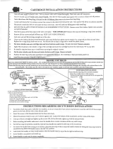
Cartridge Installation
A.
C.
Turn off water supplies. Remove
cover (1), bonnet nut (2) and test cap (3)
from the body. If this is not a thin wall
mounting, the entire plasterguard (4) may
be removed. If screen (5) is in place,
remove before installing cartridge.
B.
Insert adapter assembly (1) into valve
body. Make sure the adapter assembly
is correctly positioned and is pressed all
the way down inside body. Secure adapter
with the screw (2) provided in the adapter
assembly. Remove the retainer (3) from
the adapter.
For back to back or reverse installations
(hot on right and cold on left): Rotate
cartridge (1) so the words “HOT SIDE” (2)
appear on the right. Install the cartridge
making sure that the key is fully engaged
with the slot in the brass body (See step C).
Slide bonnet nut (3) over the cartridge and
thread onto the body. Hand tighten securely.
Back to back Installation
Rotate cartridge (1) so the words
“HOT SIDE” (2) appear on the left. Insert
cartridge assembly into valve body.
Make sure the key (3) on the cartridge is
fully engaged with the slot in the brass
body (4). Slide bonnet nut (5) over the
cartridge and thread onto the body.
Hand tighten securely.
1
2
3
1
1
3
4
Reverse
Installation
Cold
Hot
1
5
5
2
3
3
4
Normal Installation
(changes not required)
2
2
5

C.
D.
A.
B.
Slide O-ring (1) over cartridge and the
bonnet nut (2). The O-ring, which acts as
a spacer to steady the sleeve, should rest
behind the bonnet nut.
Slide the sleeve (1) over the cartridge,
body and O-ring. Ensure sleeve is properly
positioned over the front of cartridge.
Secure the escutcheon (1) and
backplate (2) (if your model has one) to the
bracket (3) with the 2 screws provided (4).
Do not overtighten escutcheon screws.
Install volume control handle (1) with
lever to the right. DO NOT SECURE
WITH SCREW.
18 Series Installation - Separate Units
3
Trim Installation
1
2
1
1
2
3
4
1
6

7
4
Showerhead and Tub Spout Installation
FOR SHOWERHEAD INSTALLATION:
Connect top outlet (1) to shower arm (2)
with proper fittings. To prevent damage
to finish on shower arm, insert wall end
of shower arm into shower flange (3)
before screwing arm into riser connection.
Thread showerhead (4) onto shower
arm. Apply plumber tape to pipe threads
on both ends. Do not overtighten
showerhead.
A.
3
2
1
Slip-On Installation
The copper tube (1) must be 1/2” nominal
copper. Important: If it is necessary to
cut the copper tube, the end must be
chamfered free of burrs to prevent cutting
or nicking O-ring inside the spout. Slide
spout over copper tube flush with the
finished tub or wall surface. Tighten set
screw (2), but do not overtighten.
4
1
FOR TUB SPOUT INSTALLATION:
Refer to the installation instructions supplied with your spout. Do not connect deck mount
spouts to in-wall valves. Do not use hand showers connected in lieu of a tub spout to a
tub/shower valve. Do not use PEX tubing for tub spout drop.
B-1
B-2
B-3
Iron Pipe Installation
Install threaded pipe nipple (1) to extend
past finished wall. Apply plumber tape to
threads on pipe nipple and screw on
tub spout.
Copper Sweat Installation
Remove O-ring (1) from adapter (2). Solder
adapter to tube taking care to keep solder
away from O-ring groove. CAUTION: NO
SOLDER PERMITTED ON OUTSIDE
DIAMETER OF ADAPTER ADJACENT
TO O-RING GROOVE. Cut off tube (3) and
replace O-ring on groove of brass adapter.
Thread tub/spout onto adapter, taking care
not to damage O-ring, and hand tighten
until spout is firmly against finished wall
and all slack is taken up behind wall.
2
1
1
2
3
18 Series Installation - Separate Units

5
Installation and Adjustment of the Rotational Limit Stop
C.
A.
B.
Place the temperature control knob (1)
on volume handle and rotate to the mixed
position (if required). DO NOT SECURE
WITH SCREW. Turn on water supplies;
let the water run until both hot and cold
water is as hot/cold as possible. Place
thermometer in a plastic tumbler, and hold
the tumbler in the water stream. Record the
temperature reading.
If the water temperature is above 120°F,
remove the temperature control knob (1)
and rotate the limit stop (2) clockwise one
tooth for every 4°F - 6°F (approximate)
change in temperature. If water temperature
is cooler than desired, rotate the limit stop
counterclockwise.
IMPORTANT: The first position of the
Rotational Limit Stop (the Limiter) is that
position that restricts the rotation of the
stem the most and is at the maximum
clockwise setting. According to industry
standards, the maximum allowable
temperature of the water exiting from the
valve is 120
o
F. This temperature may vary
in your local area. The Rotational Limit Stop
may need to be readjusted if the inlet water
temperature changes. For instance, during
the winter, the cold water temperature is
colder than it is during the summer which
could result in varying outlet temperatures.
Typical temperature for a comfortable bath
or shower is between 90
o
–110
o
F.
Secure temperature control knob (1) with
screw (2) and snap control cover (3) onto
knob. NOTE: Secure screw until handle
wobble is reduced, DO NOT FULLY
TIGHTEN. Overtightening will result in
difficulty to operate temperature control
knob. Screw is self locking.
18 Series Installation - Separate Units
1
1
2
2
1
3
8
Hotter
Colder

18 Series Installation - Single Unit
1
Cartridge Installation
A.
D.
Turn off water supplies. Remove
cover (1), bonnet nut (2) and test cap (3)
from the body. If this is not a thin wall
mounting, the entire plasterguard (4)
may be removed. If screen (5) is in place,
remove before installing cartridge.
B.
Insert adapter assembly (1) into valve
body. Make sure the adapter assembly
is correctly positioned and is pressed all
the way down inside body. Secure
adapter with the screw (2) provided in the
adapter assembly.
Rotate cartridge (1) so the words
“HOT SIDE” (2) appear on the left. Insert
cartridge assembly into valve body.
Make sure the key (3) on the cartridge is
fully engaged with the slot in the brass
body (4). Slide bonnet nut (5) over the
cartridge and thread onto the body.
Hand tighten securely.
1
2
3
1
2
1
3
4
5
2
C.
Remove the retainer (1) from the adapter.
1
9
4
5

E.
F.
Slide O-ring (1) over cartridge and the
bonnet nut (2). The O-ring, which acts as
a spacer to steady the sleeve, should rest
behind the bonnet nut.
Slide the sleeve (1) over the cartridge,
body and O-ring. Ensure sleeve is properly
positioned over the front of cartridge.
18 Series Installation - Single Unit
1
2
1
For back to back or reverse installations
(hot on right and cold on left): Rotate
cartridge (1) so the words “HOT SIDE” (2)
appear on the right. Install the cartridge
Back to back Installation
Reverse
Installation
Cold
Hot
1
3
making sure that the key is fully engaged
with the slot in the brass body (see step D).
Slide bonnet nut (3) over the cartridge and
thread onto the body. Hand tighten securely.
Cartridge Installation
10
2
Normal Installation
(changes not required)

C.
11
2
Jetted Shower™ Trim Installation
18 Series Installation - Single Unit
B.
Thread sleeve (1) onto brass body, use
wrench to tighten. Place escutcheon (2) over
jet body module. Install screws (3). Thread
the jet sleeve assemblies (4) onto the jet
body module. Use the wrench (5) to tighten
the sleeve assemblies. CAUTION: DO
NOT OVER TIGHTEN. TIGHTEN UNTIL
THE ESCUTCHEON IS FLAT AGAINST
THE WALL.
A.
1
1
2
4
2
1
Select proper label (1) (the off/on label A
is used on the standard Jetted Shower™
only) and assemble onto trim ring (2)
(Refer to chart below for proper label
selection.) Slide trim ring onto sleeve (3)
until it bottoms out on the escutcheon
(4). Install handle (5) onto stem, tighten
set screw to secure. Thread the bonnet
assemblies (6) onto the jet sleeve
assemblies (7).
1
A
B
C
2
3
4
5
Jetted
Shower™
Jetted Shower
XO™
2 Ports 3 Ports
Stem
Extender
White Blue Black
Label A B C
6
6
7
Turn off water supplies. Unscrew test
caps (1) from the body. If this is not a thin
wall mounting, the entire plasterguard may
be removed. Remove bonnet nut (2) from
the body.
5
3

2
Jetted Shower XO™ Trim Installation
A.
18 Series Installation - Single Unit
B.
1
1
A
B
C
2
3
4
5
Select proper label (1), the 3 position
label B (used with the blue stem
extender) or 6 position label C (used with
the black stem extender) and assemble
onto trim ring (2). (Refer to chart below
for proper label selection.) Slide trim ring
onto sleeve (3) until it bottoms out on the
escutcheon (4). Install handle (5) onto
stem, tighten set screw to secure. Thread
the bonnet assemblies (6) onto the jet
sleeve assemblies (7).
1
Jetted
Shower™
Jetted Shower
XO™
2 Ports 3 Ports
Stem
Extender
White Blue Black
Label A B C
7
6
Thread sleeve (1) onto brass body, use
wrench to tighten. Place escutcheon (2)
over jet body module. Install screws (3).
Thread the jet sleeve assemblies (4) onto
the jet body module. Use the wrench (5) to
tighten the sleeve assemblies.
CAUTION: DO NOT OVERTIGHTEN.
TIGHTEN UNTIL THE ESCUTCHEON IS
FLAT AGAINST THE WALL.
C.
4
2
1
5
3
Turn off water supplies. Unscrew test
caps (1) from the body. If this is not a thin
wall mounting, the entire plasterguard may
be removed. IMPORTANT: NOTE COLOR
OF BASE ON STEM EXTENDER (2)
FOR USE LATER. (SEE CHART BELOW
FOR REFERENCE.)
12
2

13
3
Showerhead Installation
18 Series Installation - Single Unit
Connect top outlet (1) to shower arm (2)
with proper fittings. To prevent damage to
finish on shower arm, insert wall end of
shower arm into shower flange (3) before
3
2
1
4
screwing arm into riser connection. Thread
showerhead (4) onto shower arm. Apply
plumber tape to pipe threads on both ends.
Do not overtighten showerhead.

4
Installation and Adjustment of the Rotational Limit Stop
C.
A.
B.
Install volume control handle (1) with lever
to the right, then turn to the on position.
DO NOT SECURE WITH SCREW. Place
the temperature control knob (2) on
volume handle and rotate to the mixed
position (if required). DO NOT SECURE
WITH SCREW. Turn on water supplies;
let the water run until both hot and cold
water is as hot/cold as possible. Place
thermometer in a plastic tumbler, and hold
the tumbler in the water stream. Record the
temperature reading.
If the water temperature is above 120°F,
remove the temperature control knob (1)
and rotate the limit stop (2) clockwise one
tooth for every 4°F - 6°F (approximate)
change in temperature. If water temperature
is cooler than desired, rotate the limit stop
counterclockwise.
IMPORTANT: The first position of the
Rotational Limit Stop (the Limiter) is that
position that restricts the rotation of the
stem the most and is at the maximum
clockwise setting. According to industry
standards, the maximum allowable
temperature of the water exiting from the
valve is 120
o
F. This temperature may vary
in your local area. The Rotational Limit Stop
may need to be readjusted if the inlet water
temperature changes. For instance, during
the winter, the cold water temperature is
colder than it is during the summer which
could result in varying outlet temperatures.
Typical temperature for a comfortable bath
or shower is between 90
o
–110
o
F.
Secure temperature control knob (1) with
screw (2) and snap control cover (3) onto
knob. NOTE: Secure screw until handle
wobble is reduced, DO NOT FULLY
TIGHTEN. Overtightening will result in
difficulty to operate temperature control
knob. Screw is self locking.
18 Series Installation - Single Unit
1
1
2
2
1
3
14
Hotter
Colder
2

1
Jetted Shower™ Jet Module Trim Installation
Turn off water supplies. Unscrew test
caps (1) from the body. If this is not a thin
wall mounting, the entire plasterguard may
be removed. Remove bonnet nut (2) from
the body.
Thread sleeve (1) onto brass body,
use wrench to tighten. Place the oval
escutcheon (2) over jet body module.
Thread the jet sleeve assemblies (3) onto
the jet body module. Use the wrench (4) to
tighten the sleeve assemblies.
CAUTION: DO NOT OVERTIGHTEN.
TIGHTEN UNTIL THE ESCUTCHEON IS
FLAT AGAINST THE WALL.
15
18T Series Installation
A.
B.
1
1
2
1
2
Select proper label (1) (the off/on label A
is used on the standard Jetted Shower™
only) and assemble onto trim ring (2)
(Refer to chart below for proper label
selection.) Slide trim ring onto sleeve (3)
until it bottoms out on the escutcheon
(4). Install handle (5) onto stem, tighten
set screw to secure. Thread the bonnet
assemblies (6) onto the jet sleeve
assemblies (7).
1
A
B
C
2
3
4
5
Jetted
Shower™
Jetted Shower
XO™
2 Ports 3 Ports
Stem
Extender
White Blue Black
Label A B C
6
6
7
C.
4
3

1
Jetted Shower XO™ Jet Module Trim Installation
A.
Turn off water supplies. Unscrew test
caps (1) from the body. If this is not a thin
wall mounting, the entire plasterguard may
be removed. IMPORTANT: NOTE COLOR
OF BASE ON STEM EXTENDER (2)
FOR USE LATER. (SEE CHART BELOW
FOR REFERENCE.)
18T Series Installation
B.
1
1
1
3
A
B
C
2
3
4
5
Select proper label (1), the 3 position
label B (used with the blue stem
extender) or 6 position label C (used with
the black stem extender) and assemble
onto trim ring (2). (See chart below for
proper label selection.) Slide trim ring
onto sleeve (3) until it bottoms out on the
escutcheon (4). Install handle (5) onto
stem, tighten set screw to secure. Thread
the bonnet assemblies (6) onto the jet
sleeve assemblies (7).
1
Jetted
Shower™
Jetted Shower
XO™
2 Ports 3 Ports
Stem
Extender
White Blue Black
Label A B C
6
7
6
Thread sleeve (1) onto brass body,
use wrench to tighten. Place the oval
escutcheon (2) over jet body module.
Thread the jet sleeve assemblies (3) onto
the jet body module. Use wrench (4) to
tighten the sleeve assemblies.
CAUTION: DO NOT OVERTIGHTEN.
TIGHTEN UNTIL THE ESCUTCHEON IS
FLAT AGAINST THE WALL.
C.
4
2
16
2

B.
1
4
4
2
3
18T Series Installation
2
Cartridge Installation
A.
Turn off water supplies. Remove
cover (1), bonnet nut (2) and test cap (3)
from the body. If this is not a thin wall
mounting, the entire plasterguard (4)
may be removed. If screen (5) is in place,
remove before installing cartridge.
1
2
3
17
C.
Slide bonnet nut (1) over the cartridge
and thread onto the body. Hand tighten
securely.
1
4
Rotate the cartridge (1) so the word
“UP” (2) appears on the top. Insert
cartridge into valve body as shown. Make
sure the cartridge tubes and O-rings (3)
are properly seated in holes at the base of
the body. Ensure the keys on the body are
fully engaged with the slots in the body (4).
For back to back or reverse installations (hot
on right and cold on left): Rotate cartridge (1)
so the word “UP” (2) appears on the bottom.
Install the cartridge making sure that the
keys are fully engaged with the slot in the
brass body (see step B). Slide bonnet nut (3)
over the cartridge and thread onto the body.
Hand tighten securely.
Back to back Installation
Normal Installation
(changes not required)
Reverse
Installation
Cold
Hot
1
3
2
5

C.
D.
A.
B.
Slide O-ring (1) over cartridge and the
bonnet nut (2). The O-ring, which acts as
a spacer to steady the sleeve, should rest
behind the bonnet nut.
Slide the sleeve (1) over the cartridge,
body and O-ring. Ensure sleeve is properly
positioned over the front of cartridge.
Secure the escutcheon (1) to the bracket
(2) with the 2 screws provided (3).
Do not overtighten escutcheon screws.
Install volume control handle (1) with
lever to the right. DO NOT SECURE
WITH SCREW.
18T Series Installation
3
Trim Installation
1
2
1
1
2
1
18
3
/