Real Fyre FPB55-24-15P Owner's manual
- Category
- Fireplaces
- Type
- Owner's manual

1
REV 5 - 0801140855
L-A2-22408
ROBERT H. PETERSON CO. • 14724 East Proctor Avenue, City of Industry, CA 91746
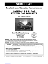
FPB 55 SERIES VENTED GAS LOG SETS
FOR NATURAL OR PROPANE GAS
Owner’s
Manual
ROBERT H. PETERSON CO.
FPB55-24/30(P)
FPB55-24/30-11(M)(P)
FPB55-24/30-15(M)(P)
Do not store or use gasoline or other
fl ammable vapors and liquids in the vicinity
of this or any other appliance.
WHAT TO DO IF YOU SMELL GAS
• Open a window.
• Do not try to light any appliance.
• Do not touch any electrical switch; do
not use any phone in your building.
• Immediately call your gas supplier from
a neighbor's phone and follow the gas
supplier's instructions.
• If you cannot reach your gas supplier,
call the fi re department.
WARNING
If the information in this manual is not
followed exactly, a fi re or explosion may
result, causing property damage, personal
injury, or loss of life.
Installation and service must be
performed by an NFI Certifi ed or
other qualifi ed professional installer,
service agency, or the gas supplier.
IMPORTANT: READ THESE INSTRUCTIONS
CAREFULLY BEFORE STARTING
INSTALLATION OF THE LOG SET.
This burner system is to be installed only in a solid-fuel-
burning fi replace with a working fl ue and constructed of
noncombustible material. Solid fuels shall not be burned
in a fi replace where this gas log set is installed. The
installation, including provisions for combustion, ventilation
air, and required minimum permanent vent opening,
must conform with the National Fuel Gas Code (ANSI
Z223.1/NFPA 54) and applicable local building codes. In
Canada, the installation must conform with the Natural
Gas and Propane Storage and Handling Installation Code
(CSA-B149.1). A damper clamp is included to maintain
the minimum permanent vent opening and to prevent
full closure of the damper blade. The chimney damper
should be fully opened when burning the log set. The
log set is designed to burn with yellow fl ames; thus,
adequate ventilation is absolutely necessary.
INSTALLER & CONSUMER:
These instructions MUST be retained
with this appliance.
®
DESIGN CERTIFIED
to
Vented Decorative Appliance
ANSI Z21.60b-2004
Important: For safe operation and proper performance of this product and to comply with certifi cation,
listings, and building code acceptances, use ONLY Peterson Real-Fyre
®
controls, parts, and
accessories that have been specifi cally listed or certifi ed for use with this burner system. Use
of other controls, parts, or accessories is prohibited and will void all warranties, certifi cations,
listings, and building code approvals, and may cause property damage, personal injury, and
loss of life.
Page is loading ...

3
REV 5 - 0801140855
L-A2-22408
TABLE OF CONTENTS
TABLE OF CONTENTS 3
GENERAL INFORMATION 4
FIREPLACE SIZE REQUIREMENTS & BTU RATING INFORMATION 4
IMPORTANT INFORMATION 5
MINIMUM PERMANENT FREE VENT OPENING AREA AT CHIMNEY DAMPER 5
PRE-INSTALLATION AND FIREPLACE PREPARATION SAFETY 7
PARTS LIST FOR MANUAL SERIES VALVE 8
PARTS LIST FOR 11 SERIES VALVE 9
PARTS LIST FOR 15 SERIES VALVE 10
INSTALLATION 11
CONNECTING THE GAS TO THE BURNER SYSTEM 11
CHECKING GAS PRESSURE 12
INSTALLATION OF DECORATIVE COVER 12
SIERRA PINE LOG LIST & PLACEMENT 13
LAVA GRANULE PLACEMENT 14
CHARRED SUMMIT PINE LOG LIST & PLACEMENT 15
LAVA GRANULE PLACEMENT 16
LIGHTING INSTRUCTIONS - MANUAL PILOT VALVE 17
LIGHTING INSTRUCTIONS - SERIES 11 VALVE 19
LIGHTING INSTRUCTIONS - SERIES 15 VALVE 21
CHECKING PILOT FLAME APPEARANCE 23
DAMPER CLAMP INSTRUCTIONS 23
TROUBLESHOOTING 24
FLAME DESCRIPTION 25
AVAILABLE ACCESSORIES FOR THE GAS BURNER SYSTEM 26
WARRANTY 28

4
REV 5 - 0801140855 L-A2-22408
APPROVED INSTALLATIONS
Subject to minimum fireplace size requirements
specifi ed below:
Solid-fuel-burning fi replaces;
A. Prefabricated fi replaces listed to UL-127
B. All other masonry fi replaces
The Real-Fyre
®
FPB55 Series gas log sets are
available with a variable fl ame height control valve that
can be used with an optional on/off remote transmitter
and receiver.
A spark ignition system (piezo) allows the gas pilot to be
lit without the use of matches and permits the operation
of the appliance during a power outage.
This log set has been certifi ed to:
VENTED DECORATIVE APPLIANCE-ANSI Z21.60b-2004
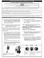
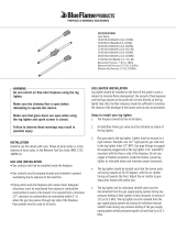
GENERAL INFORMATION
DEPTH
HEIGHT
FR ONT
WIDTH OPENING
Rear
width
Height
Front
width opening
Depth
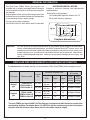
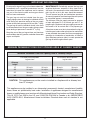
FIREPLACE SIZE REQUIREMENTS & BTU RATING INFORMATION
The minimum size of fi replace (see Fig. 4-1) for installation of Real-Fyre
®
FPB55 Series vented gas log set:
Fireplace dimensions
This unit (FPB55 gas log set) MUST NOT be placed in a fi replace with ANY dimension smaller than
the minimum fi replace size shown above. It is CRITICAL that the installer ensures that the fi replace
complies with the minimum sizes above (front & rear widths, depth & height).
Fig. 4-1
Gas type Burner model
Log set
size
Minimum fi replace size
Nominal
BTU rating
Width Depth Height
Low
variable
setting
High
variable
setting
Natural
gas
FPB55-24/30
FPB55-24/30-11
FPB55-24/30-15
24" sets
30" front
20" rear
14" 18" 22,000 to 55,000
30" sets
35" front
20" rear
14" 18" 22,000 to 55,000
Propane
gas
FPB55-24/30P
FPB55-24/30-11P
FPB55-24/30-15P
24" sets
30" front
20" rear
14" 18" 22,000 to 55,000
30" sets
35" front
20" rear
14" 18" 22,000 to 55,000
Important: For safe operation and proper performance of this product and to comply with certifi cation,
listings, and building code acceptances, use ONLY Peterson Real-Fyre
®
controls, parts, and
accessories that have been specifi cally listed or certifi ed for use with this burner system. Use
of other controls, parts, or accessories is prohibited and will void all warranties, certifi cations,
listings, and building code approvals, and may cause property damage, personal injury, and
loss of life.

5
REV 5 - 0801140855
L-A2-22408
IMPORTANT INFORMATION
MINIMUM PERMANENT FREE VENT OPENING AREA AT CHIMNEY DAMPER
Do not use this log set if any part has been underwater.
Immediately call a qualifi ed professional service
technician to inspect the appliance and to replace
any part of the control system and any gas control
that has been underwater.
The gas log set must be isolated from the gas-
supply piping system by closing its individual shutoff
valve during any pressure testing of the gas-supply
system at test pressures equal to or less than
1
/
2
psig.
The gas log set and its individual shutoff valve must
be disconnected from the gas-supply piping system
when testing at pressures in excess of
1
/
2
psig.
Keep the area of the gas log set clear and free from
combustible materials, gasoline, and other fl ammable
vapors and liquids.
MAINTENANCE: Periodically remove the logs and
examine the burner assembly. If dirty, clean with a
stiff brush. Also examine the area around burner and
pilot. Any dirt or lint in this area should be removed.
This will ensure long life and trouble-free operation.
An annual inspection and cleaning of the vent system
by a qualifi ed agency is recommended.
The minimum inlet gas-supply pressure for purpose
of input adjustment is 5" for natural gas and 11" for
propane gas. Maximum inlet gas-supply pressure for
this burner is 10" for natural and 14" for propane gas.
A fi replace screen must be in place when the log set
is burning and, unless other provisions for combustion
air are provided, the screen shall have an opening or
openings for introduction of combustion air. When a
glass fi replace enclosure (door) is used, operate the
gas log set with the glass doors open.
Minimum Permanent Free Vent Opening Area at Chimney Damper
For factory-built fi replaces
log set sizes
For masonry-built fi replaces
log set sizes
Chimney
height
15' 35 sq. in. 35 sq. in. 39 sq. in. 39 sq. in.
20' 31 sq. in. 31 sq. in. 35 sq. in. 35 sq. in.
25' 30 sq. in. 30 sq. in. - -
30' 28 sq. in. 28 sq. in. 32 sq. in. 32 sq. in.
CAUTION: This appliance may not be used or installed in a fi replace with a chimney less
than 15' in height.
This appliance may be installed in an aftermarket, permanently located, manufactured (mobile)
home, where not prohibited by local codes. Installation of appliances designed for manufactured
homes or mobile homes must conform with Manufactured Home Construction and Safety Standard,
Title 24 CFR, Part 3280 in the U.S. and CAN/CSA Z240 MH in Canada or by ANSI/NCSBCS
A225.1/NFPA 501A, Manufactured Home Installations Standard when such as standard is not
applicable.
Page is loading ...

7
PRE-INSTALLATION AND FIREPLACE PREPARATION SAFETY
A. This appliance is designed as an attended appliance. Adults must be present when this gas appliance is operating.
Do not leave this unit burning when unattended or while anyone is sleeping.
B. This appliance is only for use with the type of gas indicated on the rating plate. This appliance is NOT FIELD
CONVERTIBLE for use with other gasses.
C. BE CAREFUL: If not installed, serviced, and used correctly per these instructions, this product can cause
serious personal injury, property damage, or loss of life.
PRE-INSTALLATION AND FIREPLACE PREPARATION SAFETY GUIDELINES
D. WARNING: Before installing in a solid-fuel-burning fi replace, the chimney fl ue, damper, and fi rebox must be
thoroughly CLEANED of soot, creosote, ashes, and loose paint, and must be inspected by a qualifi ed chimney
cleaner. Some older fi replaces may need repair prior to installing this appliance.
E. CHECK GAS TYPE (natural or propane): The gas supply must be the same as stated on your burner system rating
plate. If gas supply is different, DO NOT INSTALL. Contact your dealer for immediate assistance.
F. Any outside air ducts and/or ash dumps located on the fl oor or walls of the fi replace must be permanently sealed shut
before the installation. Use a heat-resistant sealant. Do not seal the chimney fl ue damper.
G. INSUFFICIENT GAS PRESSURE WILL KEEP THE PILOT FROM OPERATING PROPERLY. DO NOT USE IF GAS
PRESSURE IS LOWER THAN THE MINIMUM REQUIREMENT.
H. The minimum inlet gas-supply pressure for purposes of input adjustment is 5" water column (w.c.) on natural gas
and 11" w.c. on propane gas. Insuffi cient gas pressure will affect proper operation of the pilot. Do not install this gas
appliance if minimum pressure is not available. The maximum inlet gas-supply pressure is 10.5" w.c. on natural gas
and 13" w.c. on propane gas. The propane source must be regulated. (Do not connect this appliance directly to an
unregulated propane gas tank - this can cause an explosion.)
I. The gas piping system must be sized to provide minimum inlet pressure at the maximum fl ow rate (BTU/hr). Undue
pressure loss will occur if the pipe is too small, or the run is too long.
J. The minimum clearance from the fi replace opening to combustible materials on side walls and ceiling must be maintained
as outlined in MINIMUM CLEARANCE TO COMBUSTIBLES - WALLS AND CEILING.
K. Be certain that combustible fl ooring material (e.g., carpet, tile, etc.) is not too close to this gas appliance. If this appliance
is at fl oor level or less than 6" above the fl oor, there must be at least 12" of noncombustible material between the base
of the fi replace and any combustible fl ooring.
L. Input ratings shown in BTU per hour are for elevations up to 2,000 ft. For elevations above 2,000 ft., refer to the National
Fuel Gas Code or contact the Robert H. Peterson Company before installing this product.
M. This gas appliance and its main gas valve must be disconnected from the gas-supply piping system during any pressure
testing of that system at test pressures in excess of
1
/
2
psig.
N. This gas appliance must be isolated from the gas-supply piping system by closing the equipment shutoff valve connected
to the gas-supply line during any pressure testing of the gas-supply piping system at test pressures equal to or less
than
1
/
2
psig.
O. Do not use this appliance if any part has been underwater. Immediately call a qualifi ed service technician to inspect the
appliance and to replace any part of the control system and any gas control that has been underwater.
CAUTION: Installation and repair must be done by an NFI Certifi ed or other qualifi ed professional
installer.
Installer: Carefully read these instructions before installing this gas burner system. Be sure you understand
all safety precautions and warnings contained in this manual.

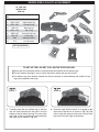
8
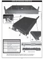
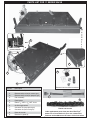
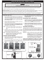
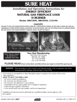
PARTS LIST FOR MANUAL SERIES VALVE
1
2
3
5
Item No. Description
1. Burner assembly
2.
or
Manual safety valve (for natural gas)
Manual safety valve (for propane gas)
3. Pilot assembly
4. Piezo ignitor
5.
Elbow,
1
/
2
" MFL x
3
/
8
" MPT, brass
6. Hi-Lo control knob
7.
or
Connector kit (for propane gas)
Connector kit (for natural gas)
8. Decorative cover for manual valve
6
4
8
Photos not to scale
Pilot assembly
(at rear of burner)
7
Order replacement parts from your local Real-Fyre
®
dealer. For a list of dealers in
your area, contact R.H. Peterson at the address on the cover of this instruction.

9
PARTS LIST FOR 11 SERIES VALVE
1
3
6
5
8
Photos not to scale
Item No. Description
1. Burner assembly
2.
or
Remote safety valve (for natural gas)
Remote safety valve (for propane gas)
3. Pilot assembly
4. Piezo ignitor
5.
Elbow,
1
/
2
" MFL x
3
/
8
" MPT, brass
6. On/Off toggle switch
7.
or
Connector kit (for propane gas)
Connector kit (for natural gas)
8. Decorative cover
9. Remote kit (optional)
Pilot assembly
(at rear of burner)
7
2
4
Order replacement parts from your local Real-Fyre
®
dealer. For a list of dealers in your area, contact R.H.
Peterson at the address on the cover of this instruction.
Remote kit with remote instructions.
9

10
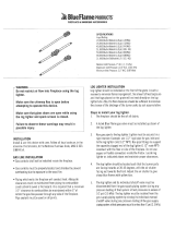
PARTS LIST FOR 15 SERIES VALVE
1
2
Pilot assembly
(at rear of burner)
Item No. Description
1. Burner assembly
2.
or
Automatic safety valve (for natural gas)
Automatic safety valve (for propane gas)
3.
Pilot assembly (natural) or
Pilot assembly (propane)
4.
Elbow,
3
/
8
" FPT x
3
/
8
" MPT, brass
5.
or
Connector kit (for propane gas)
Connector kit (for natural gas)
6. Decorative cover
7. Remote kit (optional)
5
6
Photos not to scale
Order replacement parts from your local Real-Fyre
®
dealer. For a list of dealers in
your area, contact R.H. Peterson at the address on the cover of this instruction.
Remote kit with remote
instructions.
9
4
3

11
INSTALLATION
1. MAKE SURE THE FIREPLACE GAS-SUPPLY IS
TURNED OFF.
2. Center the burner assembly in the fi replace. Make certain
that no part of the assembly protrudes beyond the face
of the fi replace.
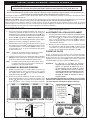
3. Use pipe compound resistant to all gasses or Tefl on tape
to attach the male NPT pipe threads of the gas-supply
line to the large adapter fi tting (Fig. 11-2). Then connect
the same-colored fl are fi tting of the fl exible connector to
the adapter. Connect the fl are fi tting at the other end of
the fl ex connector to the valve gas inlet (see
Fig. 11-1).
Tighten both fl are fi ttings.
4. Make sure that the control valve on the burner system is in
the OFF position (see
Fig. 11-3 - Fig. 11-5, depending on
which valve you have). Turn on the gas to the fi replace and
leak test all connections using a gas detector or a half-
and-half soapy water solution. If bubbles appear, a leak
is present. Turn off the gas and tighten all connections,
then turn on the gas and repeat the leak test. Repeat until
no leaks are detected.
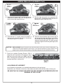
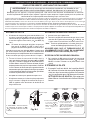
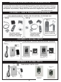
We recommend that before you install the log set, you familiarize yourself with the control valve layout. This will help
you to be confi dent operating the log set when fully installed (see fi gures below for typical control positions).
Fig. 11-4
Series 11 remote valve operating positions
OFF PILOT ON
Read setting here
Fig. 11-5
OFF IGNITION PILOT ON
Series 15 remote-capable gas valve operating
positions
Note: To install the vented gas log set, the fi replace must have a gas-supply line that has been installed
by a qualifi ed professional technician in accordance with all local codes. Refer to the PARTS LIST
when installing the vented gas log set.
CONNECTING THE GAS TO THE BURNER SYSTEM
Important: CHECK GAS TYPE (natural or propane). The gas supply must be the same as stated on
the gas log set rating plate. If the gas supply is different, DO NOT INSTALL. Contact the
dealer for immediate assistance.
Tools Required:
1. Adjustable open-ended wrench
2. Pliers
3. Teflon tape or pipe compound resistant to all
gasses
4. Soapy water solution & brush for leak detection
5. Standard screwdriver
6. Manometer (recommended for checking gas
pressure)
Important: Be sure you have read and understood all safety precautions and warnings contained in
this manual.
WARNING
Do not connect this appliance directly to a high-pressure
natural gas line or an unregulated propane tank.
NEVER USE A FLAME TO
TEST FOR GAS LEAKS.
Manual gas valve operating positions
Fig. 11-3
OFF PILOT ON
Read setting here
Attach The Flex
To Gas Supply Inlet
Connector To
The Valve Elbow
Fig. 11-1
APK-11
shown
To gas-supply inlet
Attach the fl ex
connector to
the valve elbow
WARNING
Failure to position the parts in accordance
with these diagrams or failure to use
only parts specifi cally approved with this
appliance may result in property damage
or personal injury.
Fig. 11-2
Gas-supply inlet
Use Tefl on tape or pipe
compound resistant to all
gasses on inlet but not
fl are fi ttings.
Large adapter fi tting

12
INSTALLATION (Cont.)
IMPORTANT
Check the gas pressure with the vented gas log set burning and the control set to HIGH.
The gas log set and its main gas valve must be disconnected from the gas-supply piping system during any
pressure testing of that system at test pressures in excess of
1
/
2
psig. The gas log set must be isolated from
the gas-supply piping system by closing its equipment shutoff valve during any pressure testing of the gas-
supply piping system at test pressures equal to or less than
1
/
2
psig. This is accomplished by closing the
gas-supply line valve.
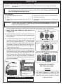
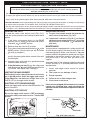
Remote-capable safety pilot valve (Fig. 12-1)
The valve regulator controls
the burner pressure, which
should be checked at the
pressure inlet tap.
Turn the inlet screw
counterclockwise 2 or 3
turns and then place the
tubing of the pressure
gauge over the pressure
inlet tap. (The test inlet
tap is under the ON/OFF/
PILOT knob). After taking
the pressure reading, be sure to turn the inlet screw
clockwise fi rmly to reseal. Do not over-torque. Check
for gas leaks.
Note: Gas pressure should be checked after
connecting the gas and prior to any
further installation.
Fig. 12-2
Manual safety pilot valve (Fig. 12-2)
The pressure regulator is preset at the factory and
locked to discourage tampering. If the pressure is not
as specifi ed, replace the regulator with the correct
part from the parts list in this manual.
To check the pressure, remove
1
/
8
" pressure tap screw
plug, located on the side of the regulator body. Install
fi tting and tubing of pressure gauge. With the unit
operating, take the pressure reading. Reinstall the
pressure tap screw and check for leaks when done.
Inlet
Outlet
Fig.
12-1
CHECKING GAS PRESSURE
INSTALLATION OF DECORATIVE COVER
FOR MANUAL VALVE:
Remove the control knob from the end of the valve stem by
pulling it forward and directly away from the burner until it comes
off (Do not rotate; See Fig. 12-3). Position the decorative cover
(p. 8, item 8) with the smooth side toward the burner and the
hole to the left. Slide the hole over the exposed valve stem until
the back of the decor cover is completely against the front of
the burner. Reattach the knob by fi rst lining up the “D” shaped
stem fi tting with the valve stem (Fig. 12-3) and then pushing
it all the way back onto the stem.
FOR AUTOMATIC VALVE:
Stand the decorative cover on the fi replace fl oor and push up
against the front of the base.
Pressure tap screw
(Underside view)
Fig. 12-3
Manual cover installation shown
Rear of valve knob
valve stem
without knob
'D' shaped
stem fi tting
Burner
face w/o
decor cover
Gas Pressure Specifi cations-
Natural Gas
MANUAL PRESSURE MILLIVOLT PRESSURE
Regulator pressure reading: 4" w.c. Outlet pressure reading:
(Flame adjustment on HI)
4" w.c.
Gas inlet pressure: Max. 10.5" w.c.
Min. 5" w.c.
Inlet pressure reading Max. 10.5" w.c.
Min. 5" w.c.
Gas Pressure Specifi cations-
Propane (L.P.) Gas
MANUAL PRESSURE MILLIVOLT PRESSURE
Regulator pressure reading: 10" w.c. Outlet pressure reading:
(Flame adjustment on HI)
10" w.c.
Gas inlet pressure: Max. 13" w.c.
Min. 11" w.c.
Inlet pressure reading Max. 13" w.c.
Min. 11" w.c.

13
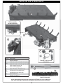
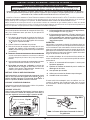
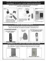
TO SET UP THE LOG SET, FOLLOW THE STEPS BELOW:
a) Burner pan has log locator studs to aid positioning and stability for the bottom logs.
b) The rear bottom log (log #1) has a hole in the base in which the rear left stud fi ts.
c) The bottom logs have location notches on the top surfaces to aid positioning and stability of top
logs (also notched in the base).
2. Place the right bottom log #2 at an angle on the
right side of the burner as shown in
Fig. 13-2. Be
sure to align the groove in the back of log #2 with
the stud on the rear right of the burner.
1. Carefully place the rear bottom log #1 with the
rear left stud inserted into the hole in the fl at
bottom of the left side of the log. The front of the
right side of the log should rest just behind the
rear right stud as shown in
Fig. 13-1.
24" LOG LIST
SIERRA PINE
(SRP-24)
SIERRA PINE LOG LIST & PLACEMENT
Fig. 13-1
STEP 1
Fig. 13-2
STEP 2
24" Log set shown
1
2
5
3
4
6
8
7
Item
No.
Part No. Description
1
SRPL-18R Rear bottom log
2
SRPL-24FR Right bottom log
3
SRPL-24FL Left bottom log
4
SRPL-9T Right top log
5
SRPL-17TY Top “Y” log
6
SRPL-10T Charred center log
7
PNL-15T Left top log
8
EM-4 Glowing Embers
9
LF-4 Lava Granules
FiFig
.
g
. 1 13-3-11
S
TEP 1
FiFig
.
g
. 1 13-3-22
S
TEP
2
9

14
SIERRA PINE LOG PLACEMENT (Cont.)
5. Place the top "Y" log #5 across the center of
the log set as shown in
Fig. 14-3. It should rest
securely on logs #1, #2 and #4.
4. Rest the right top log #4 at an angle with one
end on log #1, and the other end inside the rear
opening of log #2. (See Fig. 14-2.)
6. Place the charred center log #6 across log #3
with one of the metal grate fi ngers inserted into
the notched end. Rest the left top log #7 at an
angle on log #3 and log #5. The bark free end
should rest against the far left grate fi nger. (See
Fig. 14-4.)
Fig. 14-3
STEP 5
7. Place the supplied Glowing Embers (EM-4)
along the front and center of the burner, left to
right over the small burner ports ONLY (see
Fig.
14-5
). Covering the main fl ame ports will result in
improper operation, creating soot.
LAVA GRANULE PLACEMENT
Lava Granules are provided as an aesthetic enhancement to the gas log set.
Spread the Lava Granules on the fl oor of the fi rebox around the front and the sides of the log set.
BE SURE THAT NO GRANULES ENTER THE MAIN BURNER OR INTERFERE WITH THE
BURNING OF THE LOG SET.
3. Place the left bottom log #3 towards the front of
the burner as shown in Fig. 14-1. The log should
rest in front of the center left stud.
Fig. 14-1
STEP 3
Fig. 14-2
STEP 4
Fig. 14-4
STEP 6 & 7
CAUTION: BURN HAZARD! Logs will remain hot for some time after use. You must maintain the log layout as
shown to ensure proper operation of the log set. If you need to reposition any log to maintain the
proper layout, use heat-resistant gloves, or allow logs adequate time to cool before handling.
Fig. 14-5
STEP 7
4
5
3
11
4-4-
33
P 5
5
g
.
g
. 1 14-4-44
P
6
&
7
7
6

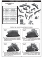
15
12
13
TO SET UP THE LOG SET, FOLLOW THE STEPS BELOW.
2. Rest Log #2 on the right side of Log #1 as shown
in Fig. 15-2 with the notched end resting against
the right most fi nger of the grate.
1. Set Log #1 on the burner (with fl at side down),
lining up the notches on the bottom of the log with
the pegs on the burner.
24" LOG LIST
CHARRED SUMMIT PINE
(CHSP-24)
CHARRED SUMMIT PINE LOG LIST & PLACEMENT
Fig. 15-1
STEP 1
Fig. 15-2
STEP 2
1
2
5
3
4
6
8
7
Item
No.
Part No. Description
1
CHSPL-19R Ripped log
2
CHSPL-15 Branching log
3
PNL-15T Curved log
4
OCBWL-9 Burnt half log
5
CHSPL-14 Charred stripped log
6
EBVL-10T Small charred stripped
log
7
CHSPL-16 Charred gnarled log
8
CHSPL-10 Charred knotty log
9
CHSPL-9 Forked top log
10
CHSPL-12 Charred bottom log
11
CHK-10 Wood chunk
12
LF-4 Lava Granules
13
EM-4 Glowing Embers
10
11
9
4. Lay the larger side of Log #4 across the lower part of
Log # 3 as shown in Fig. 15-4 so that the smaller
end rests on the burner between Logs #2 and #3.
3. Place Log #3 so that the fl at sits on top of the
burner between the grate fi ngers second and third
from the right and the other end rests across the
center of Log #1 (Fig. 15-3).
Fig. 15-3
STEP 3
Fig. 15-4
STEP 4

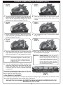
16
CHARRED SUMMIT PINE LOG PLACEMENT (Cont.)
6. Place the notched end of Log #6 against grate
fi nger second from the left and the other end atop
Log #3.
11. Place the supplied embers (EM-4) along the front
and center of the burner, left to right over the small
burner ports ONLY (see
Fig. 16-7). Covering the
main fl ame ports will result in improper operating,
creating soot.
The supplied wood chunk is for decorative use. Place the
wood chunk on the fi replace fl oor at the left side of the
burner, slightly in front of the valve.
LAVA GRANULE PLACEMENT
Lava Granules are provided as an aesthetic enhancement to the gas log set. Spread the Lava Granules on the
fl oor of the fi rebox around the front and the sides of the log set.
BE SURE THAT NO GRANULES ENTER THE MAIN BURNER OR INTERFERE WITH THE
BURNING OF THE LOG SET.
5. Lay the fl at on the charred side of Log #5 on the open
space on the left of the burner against the base of
Log #1 with the stripped side resting on top of the
forward end of Log #4 as shown in Fig. 16-1.
Fig. 16-1
STEP 5
Fig. 16-2
STEP 6
CAUTION: BURN HAZARD! Logs will remain
hot for some time after use. You must
maintain the log layout as shown to
ensure proper operation of the log set.
If you need to reposition any log to
maintain the proper layout, use heat-
resistant gloves or allow logs adequate
time to cool before handling.
Fig. 16-7
STEP 11
8. Lay Log #8 across Logs #7, #6, and #5 as shown
in Fig. 16-4.
7
. Set the notched end of Log #7 against the left most
fi nger of the grate so the middle rests on Log #1 and
the end on Log #3 (Fig. 16-3).
Fig. 16-3
STEP 7
Fig. 16-4
STEP 8
10. Rest Log #10 over Log #5 and Log #3 with its
charred section facing Log #9.
9
. Rest the stripped section of Log #9 against the grate
fi nger second from the right with the charred section
side to the left and the “Y” end supported on Log #2.
Fig. 16-5
STEP 9
Fig. 16-6
STEP 10
WARNING: Failure to position the parts in accordance
with these diagrams or failure to use
only parts specifi cally approved with this
appliance may result in property damage
or personal injury.

LIGHTING INSTRUCTIONS - MANUAL PILOT VALVE
The Real-Fyre
®
burner system has a pilot that can be lit by hand using a match or lighter. When lighting the pilot, follow these
instructions exactly.
BEFORE LIGHTING, smell all around the burner area for gas. Be sure to smell next to the fl oor, as some gas is heavier than
air and will settle on the fl oor. IF YOU SMELL GAS, FOLLOW THE INSTRUCTIONS ON P. 1.
Use only your hand to push in or turn the gas control knob. Never use tools. If the knob will not push in or turn by hand, don't
try to repair it. Call a qualifi ed professional service technician. Force or attempted repair may result in fi re or explosion.
WARNING
If you do not follow these instructions exactly, a fi re or explosion may result, causing property
damage, personal injury, or loss of life.
Do not use this appliance if any part has been underwater. Immediately call for a qualifi ed professional service technician to
inspect the appliance and to replace any part of the control system and any gas control that has been underwater.
FOR YOUR SAFETY, READ BEFORE LIGHTING
LIGHTING THE PILOT
1. If the burner control valve knob is not in the OFF
position, push in the gas control handle slightly
and turn clockwise
to OFF (Fig. 17-1).
Refer to the PARTS LIST for the location of the
burner control valve knob.
Note: The burner control knob cannot be turned
from PILOT to OFF unless the handle is
pushed in slightly. Do not force.
Wait fi ve minutes to clear out any gas. If you then
smell gas, STOP! Notify your gas supplier or the
fi re department immediately. If you don’t smell gas,
go on to step 2.
2. Turn the burner control knob counter-clockwise
to PILOT (Fig. 17-1). Push the control
handle all the way in and hold it. Hold a long
fi replace match or lighter near the thermocouple
to light the pilot. Continue to hold the control
knob for approximately 30 seconds after the
pilot is lit to allow the thermocouple to detect
the pilot fl ame, then release the knob. The pilot
will remain lit.
• If the pilot will not light, repeat steps 1 and 2.
• If the pilot will not stay lit after several tries, turn
the gas control handle to OFF and call your
service technician or gas supplier.
IGNITING THE MAIN BURNER
1. Make sure the pilot is burning.
2. Turn the gas control handle counterclockwise
to ON (Fig. 17-1) to ignite the burner. The
burner will ignite.
Note: Periodically check the pilot fl ame for the
proper fl ame pattern (
Fig. 17-1).
MAKE SURE THE THERMOCOUPLE AND PILOT
ASSEMBLY ARE IN CORRECT ALIGNMENT WITH
EACH OTHER (
Fig. 17-1).
TURNING OFF THE MAIN BURNER
1. From the ON position, turn the control knob
clockwise
to the PILOT position. The burner
will extinguish, and the pilot will remain lit.
EXTINGUISHING THE PILOT
1. If complete shutdown is desired, from the PILOT
position, push in the control knob slightly and
turn clockwise
to the OFF position. Do not
force the knob. This will require the pilot to be
relit before using the burner again.
17
1. Turn the knob
clockwise to
OFF
only
when complete
shutdown is
desired.
Fig. 17-1
1. Lighting -Turn the burner control knob
to OFF
and wait 5 minutes before
lighting.
2. Turn knob
counterclockwise
to PILOT position. With
match ready, press
knob in and hold for 60
seconds while lighting
pilot.
3. Turn the knob
counterclockwise
to ON to light the
burner.
PILO T
ON
OFF
OFF
ON
PILOT
OFF
ON
PILOT
OFF
ON
PILOT
Thermocouple
The Real-Fyre
®
burner system has a pilot that can be lit using the built-in piezo ignitor switch on the burner, or by hand using
a match or long-necked lighter. When lighting the pilot, follow these instructions exactly.
2. Turn the burner control knob counterclockwise
to PILOT (Fig. 17-1). Push the control
handle all the way in and hold it. Push in the
piezo ignitor button several times until the pilot
lights. Continue to hold the control knob for
approximately 60 seconds after the pilot is lit
to allow the thermocouple to detect the pilot
fl ame, then release the knob. The pilot will
remain lit.
Page is loading ...

ADJUSTING THE PILOT
a. The pilot fl ame should encircle the generator tip,
and is preset at the factory (Fig. 19-2).
b. If adjustment is necessary (Fig.19-1), turn the gas
adjustment screw counterclockwise
to increase
the pilot fl ame, or clockwise
to decrease the
pilot fl ame.
MAINTENANCE
Your pan burner is equipped with a safety pilot that will
shut off the gas supply in the event that the pilot is not
functioning properly. Make sure the pilot is adjusted
properly and that the generator spade clips are tightly
connected to the terminal screws on the valve. If the
pilot will not stay lit, call your local gas utility or gas
supplier.
A periodic check of the following should be performed
at least annually by a qualifi ed professional service
representative:
1. Valves and toggle switch control for proper
operation.
2. Flue system for rust, damage, or leaks.
3. Damper operation.
4. Orifi ces for dirt or other foreign matter.
5. Visual check on the burner.
If this unit was shipped with a remote, or if a remote
system was installed later, read and follow the
separate remote instructions to operate the burner
remotely.
WARNING
If you do not follow these instructions exactly, a fi re or explosion may result, causing property
damage, personal injury, or loss of life.
Do not use this appliance if any part has been underwater. Immediately call for a qualifi ed professional service technician
to inspect the appliance and to replace any part of the control system and any gas control that has been underwater.
FOR YOUR SAFETY, READ BEFORE LIGHTING
LIGHTING THE PILOT
To read the safety valve control knob (Fig. 19-1),
read the marking nearest the teardrop-shaped metal
pointer.
1. If the safety valve control knob is in the PILOT
position, push in slightly on the knob and rotate it
clockwise
to the OFF position.
2. Release knob and wait fi ve (5) minutes.
3. Turn safety valve knob counterclockwise to the
PILOT position. (Only the pilot gas will fl ow when
the knob is pushed in.)
4. Place a long match or a butane lighter at the pilot
burner, and at the same time, push the safety valve
knob fully in. The pilot will light.
5. Hold the safety valve knob in for approximately 60
seconds before releasing.
6. If the pilot does not stay lit, turn the safety valve
knob clockwise
to the full OFF position. Wait fi ve
(5) minutes, then repeat steps 3 through 5.
IGNITING THE MAIN BURNER
With the pilot lit, turn the safety valve knob counterclockwise
to the ON position. Switch the toggle switch control
to the ON position, and the burner will light.
Refer to the
PARTS LIST for the toggle switch location.
SHUTTING OFF THE MAIN BURNER
Switch the toggle switch control to the OFF position. The
pilot will remain lit.
SHUTTING OFF THE PILOT
Be sure the toggle switch control is OFF and depress
and turn the safety valve knob
clockwise to the OFF
position.
Fig. 19-1
Wiring harness
Toggle switch
Pilot screw
Pilot gas
port
control
knob
Safety
valve
IN
TH
TP
TH
TP
IN
OUT
19
LIGHTING INSTRUCTIONS - SERIES 11 VALVE
The Real-Fyre
®
burner system has a pilot that can be lit by hand using a match or lighter. When lighting the pilot, follow
these instructions exactly.
BEFORE LIGHTING, smell all around the burner area for gas. Be sure to smell next to the fl oor, as some gas is heavier than
air and will settle on the fl oor. IF YOU SMELL GAS, FOLLOW THE INSTRUCTIONS ON P. 1.
Use only your hand to push in or turn the gas control knob. Never use tools. If the knob will not push in or turn by hand, don't
try to repair it. Call a qualifi ed professional service technician. Force or attempted repair may result in fi re or explosion.
Generator
Pilot
Note: Pilot fl ame should encircle top of the generator.
Fig. 19-2 Lighting the pilot
The Real-Fyre
®
burner system has a pilot that can be lit by using the built-in piezo ignitor switch on the burner, or by hand
using a match or long-necked lighter. When lighting the pilot, follow these instructions exactly.
4. Push and hold the safety valve knob fully in and
push in the piezo ignitor button several times until
the pilot lights.
Fig. 19-1
Wiring harness
Toggle switch
Pilot screw
Pilot gas
port
control
knob
Safety
valve
IN
TH
TP
TH
TP
IN
OUT
Generator
Pilot
Electrode
Page is loading ...

WARNING
If you do not follow these instructions exactly, a fi re or explosion may result, causing property
damage, personal injury, or loss of life.
LIGHTING INSTRUCTIONS - SERIES 15 VALVE
Do not use this appliance if any part has been underwater. Immediately call for a qualifi ed professional service technician
to inspect the appliance and to replace any part of the control system and any gas control that has been underwater.
Gas valve operating positions
OFF IGNITION PILOT ON
Fig. 21-1
Flame-height control knob
Fig. 21-4
Fig. 21-3
LIGHTING THE PILOT
1. Turn the ignitor control knob (Fig. 21-1) on the burner
control valve assembly to the side of the burner pan
counterclockwise so that the narrowing part of the
knob moves from the OFF position, slightly toward IGN,
until reaching the stop.
2. Press the ignitor control knob in and hold in for fi ve (5)
seconds (only pilot gas will fl ow).
3. Continue pressing in while turning the ignitor control knob
further counterclockwise toward the PILOT position
until you hear a click. The click is an indication that the
piezo ignitor has been activated.
Note: If the spark from the piezo ignitor does not
light the pilot, repeat steps 2 & 3 until the pilot
lights.
4. Continue to hold the ignitor control knob in the PILOT
position for 60 seconds after the pilot has been lit to allow
the thermocouple to detect the pilot fl ame.
Note: The pilot fl ame should always be present when
the burner system is in operation, and should just
envelop the tip of the thermocouple.
IGNITING THE MAIN BURNER
1. When the pilot fl ame is stable, release the ignitor control
knob and turn counterclockwise to the ON position
to enable the main burner.
2. Turn the flame-height control knob (Fig.
21-3)
counterclockwise
to the fully ON position
(Fig. 21-4) to ignite the burner at maximum BTUs.
After the main burner ignites, adjust the fl ame height
as indicated below.
ADJUSTING THE FLAME HEIGHT
1. To adjust the fl ame, turn the fl ame-height control knob
(Fig. 21-3) counterclockwise to increase the fl ame
height, or clockwise to decrease the fl ame height,
until the fl ames have the desired characteristics.
2. When you are fi nished enjoying your fi re, turn the fl ame-
height control knob to OFF. The pilot will remain lit. The
burner system can be relit by rotating the fl ame-height
control knob toward ON.
SHUTTING OFF THE PILOT
If you do not plan on using your burner system for an
extended period, you may elect to extinguish the pilot. To do
this, rotate the fl ame-height control knob to the OFF position
and then rotate the ignitor control knob to the OFF position
(Fig. 21-1).
Important: When shutting the burner system down
completely, turn the control/ignition knob to
the OFF position (Fig. 21-1). If you desire to
turn the unit back on, wait a minimum of one
(1) minute before starting the relight procedure
(LIGHTING THE PILOT). This allows the safety
valve to reset in preparation for relighting.
If this unit was shipped with a remote, or if a remote
system was installed later, read and follow the separate
remote instructions to operate the burner remotely.
FOR YOUR SAFETY, READ BEFORE LIGHTING
Control/
ignition
knob
Flame-height
control knob
OFF ON
21
Fig. 21-2
Thermocouple
The Real-Fyre
®
burner system has a pilot. When starting the pilot, follow these instructions exactly.
BEFORE LIGHTING, smell all around the gas burner system area for gas. Be sure to smell next to the fl oor, as some gas
is heavier than air and will settle on the fl oor. IF YOU SMELL GAS, FOLLOW THE INSTRUCTIONS ON P. 1.
Use only your hand to push in or turn the gas control knob. Never use tools. If the knob will not push in or turn by hand, don't
try to repair it. Call a qualifi ed professional service technician. Force or attempted repair may result in fi re or explosion.
Fig. 21-2
Thermocouple
Page is loading ...

23
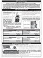
CHECKING PILOT FLAME APPEARANCE
IMPORTANT
For all valves, the air MUST be purged from the gas line before the pilot will light properly. The time taken
to do this will depend on the length of gas line from the meter to the unit and the length of time since the
unit or gas line was last used (in the case of non-use during warm weather, for example). It may take from
3-10 minutes before all the air is purged and the pilot will light properly. To do this, use the method used
for lighting the pilot, which varies depending on which valve is fi tted to the unit. Follow the LIGHTING
INSTRUCTIONS in this manual for method.
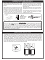
The damper clamp with hex bolt (
Fig. 23-2) is provided as a means to prevent full closure of the damper
blade. The clamp is easily attached to most damper blades with pliers or a wrench, and must be permanently
installed. The clamp is designed to prevent accidental closure of the damper when installed as illustrated
(Fig. 23-3 and Fig. 23-4). The chimney damper must be fi xed in a manner to maintain the permanent
free opening (as specifi ed in the section entitled MINIMUM PERMANENT FREE VENT OPENING AREA
OF CHIMNEY DAMPER) at all times. Should the clamp not fi t, or fail to provide the permanent vent opening
listed in the table found on p. 5, have a permanent stop installed, remove the damper blade, or have the
damper cut to provide the minimum permanent opening required.
Fig. 23-2
Damper clamp
DAMPER CLAMP INSTRUCTIONS
The pilot burner is preset at the factory and should
normally not require any adjustment. However, should
adjustment be necessary, the following steps should
be taken:
With the pilot burner lit and the control knob in the
pilot position, remove heat shield covers. Adjust screw
located on the control valve (see
Fig. 23-1). Using
a screwdriver, turn the pilot adjustment screw slowly
clockwise to reduce the fl ame, or counterclockwise
to increase the fl ame. The adjustment screw can
be turned so that the pilot flame is completely
extinguished. The pilot fl ame should be a quiet soft
blue fl ame with yellow tipping that encircles the
thermocouple tip.
Replace heat shield covers. Turn the control knob to
the ON position to ensure proper ignition of log set.
Periodically check the pilot to verify that it is burning
in proper alignment as indicated in the above
paragraphs and in Fig. 23-1.
Fig. 23-1
Example of burner
pilot fl ame with
thermopile
Example of burner
pilot fl ame with
thermocouple
Fig. 23-3 Fig. 23-4
Open
Closed
Pilot
adjustment
location
Set screw

24
POSSIBLE CAUSE SOLUTIONS
BURNER SHUTTING DOWN DURING OPERATION
A. Insuffi cient or excessive gas
pressure
A1. Check gas pressure (check with local gas company). For natural gas, pressure
must be minimum 5" w.c. at fi replace with burner operating. Maximum inlet
gas pressure is 10.5" w.c. Reading at inlet pressure tap (farthest to valve
inlet) on remote valves’ burners should be 5" w.c. (minimum). With the knob
on high, maximum inlet pressure is 10.5" w.c.
A2. Other gas appliances may be on the same gas line, dropping gas pressure
to log set. Check pressures with everything operating to ensure adequate
pressure.
B. Log placement B. Reference the LOG PLACEMENT section in this manual for recommended
log positioning.
C. Flue area, fireplace, or
damper dirty from soot
C. Clean around, above, and under damper thoroughly. Clean fi replace, removing
loose material, including soot and creosote.
D. Fireplace too small for unit D. Ensure minimum requirements are met. (See FIREPLACE SIZE
REQUIREMENT section in this owner’s manual.)
E. Pilot flame lifting off
thermocouple/generator
E. Check gas pressure (see section A1).
F. Pilot (remote compatible) F. Contact your dealer for instructions on replacement.
G. Blockages on burner G. Vacuum any lava granules or material that may have fallen onto burner pipe
area.
PILOT WILL NOT LIGHT
A. Pilot flame lifting off
thermocouple/generator
A. Check gas pressure.
B. Piezo spark not lighting
pilot
B. Check to make sure piezo is sparking when activated.
Note: You may need to turn or press ignitor several times to ignite pilot. See
LIGHTING INSTRUCTIONS for your control valve.
C. Ignitor electrode wire loose C. Check wiring and reconnect any loose wiring.
D. Gas supply off/manual
shutoff valve closed
D. Turn on gas supply or open manual shutoff valve.
E. Air in gas line E. Hold control knob in to bleed the line and repeat LIGHTING INSTRUCTIONS
until air is removed.
TROUBLESHOOTING
2
1
LOW FLAME HEIGHT
A. Gas pressure A. Check gas pressure.
B. Propane tank running low B. Fill tank completely.
BURNER NOT BURNING EVENLY
A. Burner orifi ce clogged A. Clean burner orifi ce.
B. Top burner lights; bottom
burner has delayed ignition.
B1. Check gas pressure. Can be caused by too small of a gas line (See ANSI
223.1/NFPA 54 Piping Guidelines).
B2. Low propane tank level. Vacuum burner tube for soot blockage and fi ll propane
tank.
ODORS
A. Gas leak A. Shut off gas, if possible. Follow instructions on front page. Have a qualifi ed
professional installer or the gas company correct all leaks.
B. New home, new carpet, or
new paint
B. When these odors are drawn into the fi replace, this may cause objectionable
odors. Thoroughly ventilate the area before restarting your log set.
3
4
5

25
POSSIBLE CAUSE SOLUTIONS
SOOTING
A. On logs, in fi rebox, or room A. Check gas pressure.
B. Drafts in room B. Eliminate drafts by closing heating and air conditioning
vents, returns, and outside air vents. Fans blowing directly
into fi replace should be turned off when set is operating.
C. Air shutters blocked C. Air shutters are blocked with debris. Vacuum debris away
from air shutter.
D. Log placement D. See solution in troubleshooting 1B.
E. Using natural-gas burner on propane gas or
propane burner on natural gas
E. If the gas listed on the nameplate does not match the gas
you are burning, shut down the burner system immediately
and completely (including pilot) following the steps in
the LIGHTING INSTRUCTIONS section. Then call your
dealer.
F. Adding any accessories to log sets F. Shut down log set and take off any logs or accessories that
do not belong with the set.
PILOT WILL NOT STAY LIT WHEN KNOB IS RELEASED
A. Valve won’t hold A. Contact your dealer for instructions on replacement.
6
7
TROUBLESHOOTING (Cont.)
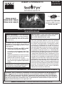
Observe the flames. The main burner flames
should be blue at the base and a combination of
blue/yellow at the body and at the tips. They should
be 5" to 8" above the logs, with the center fl ame
being the tallest (see cover photo). The ember
fl ames should be
1
/
4
" above the embers.
FLAME DESCRIPTION
Page is loading ...
Page is loading ...
Page is loading ...
-
 1
1
-
 2
2
-
 3
3
-
 4
4
-
 5
5
-
 6
6
-
 7
7
-
 8
8
-
 9
9
-
 10
10
-
 11
11
-
 12
12
-
 13
13
-
 14
14
-
 15
15
-
 16
16
-
 17
17
-
 18
18
-
 19
19
-
 20
20
-
 21
21
-
 22
22
-
 23
23
-
 24
24
-
 25
25
-
 26
26
-
 27
27
-
 28
28


Real Fyre FPB55-24-15P Owner's manual
- Category
- Fireplaces
- Type
- Owner's manual
Ask a question and I''ll find the answer in the document
Finding information in a document is now easier with AI
in other languages
Related papers
-
Real Fyre GF Owner's manual
-
-
-
-
-
-
Real Fyre GR47 Rumford Vented Burner Owner's manual
-
-
-
Other documents
-
R.H. Peterson G45 Series Owner's manual
-
Emberglow ACC16 Installation guide
-
 Sure Heat VMR24NG Installation And Operating Instructions Manual
-
-
-
-
 Blue Flame LLA.4268.NG Installation guide
-
 Sure Heat BRO24NG Installation guide
-
 Blue Flame LLA.1220.NG Installation guide
-
Desa Tech CPVSA24M Owner's manual


