Page is loading ...

INSTALLATION MANUAL
For Thermador Professional ®PRO-GRAND TM
Dual Fuel Ranges
MANUEL D'INSTALLATION
Pour cuisiniere & combustion jumelee
Professional ® PRO-GRANDTM de
Thermador
MANUAL DE INSTALACION
Para Estufas de Todo Tipo de Gas
Professional ® PRO-GRANDTM de
Thermador
Models/
Modeles /
Modelos:
PRD30
PRD36
PRD48

Table of Contents
Safety Instructions .............................. 1
Important Installation Information ................. 2
Step 1: Ventilation Requirements ...................................... 3
Step 2: Cabinet Preparation ........................................... 4
Step 3: Unpacking and Moving the Range ............................... 8
Step 4: Installing Anti-Tip Device ...................................... 9
Step 5: Gas Requirements and Hookup ................................ 11
Step 6: Electrical Requirements, Connection & Grounding ................ 13
Step 7: Backguard Installation ........................................ 16
Step 8: Door Removal and Reinstallation ............................... 18
Step 9: Placing and Leveling the Range ................................ 19
Step 10: Burner Test and Adjustment .................................. 21
Installer Checklist .................................................. 22
To Clean and Protect Exterior Surfaces ........... 22
This Thermador Appliance is made by
BSH Home Appliances Corporation
5551 McFadden Ave.
Huntington Beach, CA 92649
Questions?
1-800-735-4328
www.thermador.com
We look forward to hearing from you!

Safety Instructions
Important Safety Instructions
-- READ AND SAVE THESE INSTRUCTIONS
APPROVED FOR ALL RESIDENTIAL APPLIANCES
FOR RESIDENTIAL USE ONLY
IMPORTANT: Save these Instructions for the Local Gas
Inspector's use.
INSTALLER: Please leave these Installation Instructions
with this unit for the owner.
OWNER: Please retain these instructions for future
reference.
WARNING:
Disconnect power before installing. Before
turning power ON, be sure that all controls are in
the OFF position.
Important:
Local codes vary. Installation, gas connections and
grounding must comply with all applicable codes.
WARNING:
• All Ranges can tip.
• Injury to Persons could
result.
• Install Anti-Tip Device
packaged with range.
• See Installation
Instructions.
TO REDUCE THE RISK OF TIPPING
OF THE APPLIANCE, IT MUST BE
SECURED BY A PROPERLY
INSTALLED ANTI-TIP DEVICE.
VERIFY THAT THE ANTI-TIP DEVICE
IS ENGAGED PER INSTALLATION
INSTRUCTIONS. (.NOTE: ANTI-TIP
DEVICE IS REQUIRED ON ALL 30"
AND 36" RANGES; 48" RANGES DO
NOT REQUIRE AN ANTI-TIP DEVICE).
WARNING:
If the information in this manual is
not followed exactly, a fire or
explosion may result causing
property damage, personal injury or
death.
Do not store or use gasoline or other
flammable vapors and liquids in the
vicinity of this or any other appliance.
-- WHAT TO DO IF YOU SMELL GAS
• Do not try to light any appliance.
• Do nottouch any electrical switch.
• Do not use any phone in your
building.
• Immediately call your gas supplier
from a neighbor's phone. Follow
the gas supplier's instructions.
• If you cannot reach your gas
supplier, call the fire department.
Installation and service must be
performed by a qualified installer,
service agency or the gas supplier.
For Massachusetts Installations:
1. Installation must be performed by a qualified or
licensed contractor, plumber or gas fitter qualified or
licensed by the state, province or region where this
appliance is being installed.
2. Shut-off valve must be a "T" handle gas cock.
3. Flexible gas connector must not be longer than 36
inches.
Note:
This Range is NOT designed for installation in
manufactured (mobile) homes or for installation in
Recreational Park Trailers.
DO NOT install this range outdoors.
English 1

_j[__; _ii_11__ ...................................................................................................................................................................................................................................................................................................................................................................................................,_
Important Installation Information
GAS Type Verification
Verify the type of gas supplied to the location. Ensure that
the appliance is connected to the type of gas for which it is
certified. All models are certified for use with natural gas.
Field conversion of the appliance for use with propane gas
supply will require a conversion kit.
WARNING:
To avoid possible burn or fire hazard, a
backguard designed specifically for this range
must be installed whenever the range is used.
Refer to "Chart C: Backguard Kit Model Numbers" on
page 18, for the correct backguard models that are
designed for this range. After selecting the correct
backguard, the range must be installed properly, using the
minimum clearances to combustible surfaces specified in
"Step 2: Cabinet Preparation" on page 4.
Important:
• A backguard must be utilized when there is less than a
12" horizontal clearance between combustible
materials and the back edge of the range. A
Thermador backguard must be ordered separately and
installed at the rear of the range. (A Low Back is
supplied with the 30" model.) For island installations
and other installations with more than 12" clearance,
an optional stainless steel Island Trim is available to
cover the backguard mounting flanges.
• Verify that the appliance is correct for the type of gas
being provided. Refer to "Step 5: Gas Requirements
and Hookup" on page 11 before proceeding with the
installation.
Gas Supply:
Natural Gas - 6 inch water column. (14.9 mb) min., 14 inch
(34.9 mb) maximum
Propane Gas - 11 inch water column. (27.4 mb) min.,
14 inch (34.9 mb) maximum
Electric Power Supply:
See page 13 for specifications.
This appliance has been tested in accordance with ANSI
Z21.1, Standard for Household Cooking Appliances (USA)
and in accordance with CAN 1.1-M81 Domestic Gas
Ranges (Canadian).
It is stronqlv recommended that this appliance be installed
in conjunction with a suitable overhead vent hood. (See
"Step 1: Ventilation Requirements" on page 3.) Due to the
high heat capability of this unit, particular attention should
be paid to the hood and duct work installation to assure it
meets local building codes.
Check local building codes for the proper method of
appliance installation. Local codes vary. Installation,
electrical connections and grounding must comply with all
applicable codes. In the absence of local codes the
appliance should be installed in accordance with the
National Fuel Gas Code ANSI Z223. I/NFPA 54 current
issue and National Electrical Code ANSI/NFPA 70-current
issue. In Canada, installation must be in accordance with
the CAN 1-B149.1 and .2 - Installation Codes for Gas
Burning Appliances and/or local codes.
This appliance complies with one or more of the following
standards:
• UL 858, Standard for the Safety of Household Electric
Ranges
• UL 923, Standard for the Safety of Microwave Cooking
Appliances
• UL 507, Standard for the Safety of Electric Fans
• ANSI Z21.1, American National Standard for
Household Cooking Gas Appliances
• CAN/CSA-C22.2 No. 113-08 Fans and Ventilators
• CAN/CSA-C22.2 No. 61-08 Household Cooking
Ranges
It is the responsibility of the owner and the installer to
determine if additional requirements and/or standards
apply to specific installations.
Due to the high heat of the cooktop burners, installing a
microwave oven with a ventilation system over the cooktop
is not recommended.
English 2

CAUTION:
To eliminate risk of burns or fire caused by
reaching over heated surface units, cabinet
storage located above the surface units should
be avoided.
CAUTION:
When connecting the unit to propane gas, make
certain the propane gas tank is equipped with its
own high-pressure regulator in addition to the
pressure regulator supplied with the range. The
maximum gas pressure to this appliance
must not exceed 14.0 inches water column
(34.9 mb) from the propane gas tank to the
pressure regulator.
CAUTION:
This unit is designed as a cooking appliance.
Based on safety considerations, never use it for
warming or heating a room.
Step 1: Ventilation
Requirements
It is stronqly recommended that a suitable exhaust hood be
installed above the range. Downdraft ventilation should not
be used. The table on page 4 indicates the ventilation hood
options and blower capacity guidelines that are
recommended for use with all Thermador ranges.
1. Select Hood and Blower Models:
• For wall installations, the hood width must, at a
minimum, equal the width of the range. Where space
permits, a hood larger in width than the range may be
desirable for improved ventilation performance.
For island installations, the hood width should, at a
minimum, overhang the range by 3" on each side.
Important:
Ventilation hoods and blowers are designed for use with
single wall ducting. However, some local building codes or
inspectors may require double wall ducting. Consult local
building codes and/or local agencies, before starting, to
assure that hood and duct installation will meet local
requirements.
Do not install a microwave oven/ventilator combination
above the range, as these type of units do not provide the
proper ventilation and are not suitable for use with the
range.
2. Hood Placement:
For best smoke elimination, the lower edge of the hood
should be installed 30" above the range cooking
surface. (See Figure 1).
If the hood contains any combustible materials (i.e. a
wood covering), it must be a minimum of 36" above the
cooking surface.
NOTICE:
Most range hoods contain combustible components which
must be considered when planning the installation.
.
Consider Make-Up Air:
Due to the high volume of ventilation air, a source of
outside replacement air is recommended. This is
particularly important for tightly sealed and insulated
homes.
A qualified heating and ventilating contractor should be
consulted.
English 3

30"
36"
4 burners
4 burners with griddle
6 burners
48" 6 burners with griddle
Important Notes:
30" or 36" Pro Wall Hood
30" or 36" Custom Insert w/optional blower
42" Island Hood w/optional blower
36" or 42" Pro Wall Hood
36" Custom Insert w/optional blower
42" or 48" Island Hood w/optional blower
48" or 54" Pro Wall Hood
48" Custom Insert w/optional blower
It is recommended that a Thermador Professional wall or island hood or custom insert is used with Thermador
Professional Ranges.
Refer to www.Thermador.com for a complete selection of Professional Ventilation options, Blowers, and Accessories.
* For high output gas ranges (60,000 BTU or greater), the minimum of one (1) CFM of ventilation per 100 BTU is
recommended. If the range has a griddle, add 200 CFM to the estimated blower capacity. Additional blower capacity
may be required for longer duct runs.
For island applications, it is recommended to use a hood width that exceeds the width of the range by 6" (overlapping
the range by a minimum of 3" on each end).
CFM = "cubic feet per minute" (standard blower capacity rating).
Step 2: Cabinet Preparation
1. The range is a free standing unit. If the unit is to be
placed adjacent to cabinets, the clearances shown in
Figure 1 are required. The same clearances apply to
island installations, except for the overhead cabinets,
which must have a space wide enough to accept the
flared island hood, as indicated in Figure 1.
2. The 36" ranges may be recessed into the cabinets
beyond the edge of the front face of the oven (See
Figure 2).The 30" and 48" ranges are not approved to
be installed flush with the cabinets
,_ CAUTION:
In these installations, the door and cabinet on
36-inch models can cause a pinching hazard.
3. The gas and electrical supply should be within the zone
shown in Figure 3a.
Note:
The maximum depth of over head cabinets installed on
either side of the hood is 13" (330mm).
A 36-inch minimum clearance is required between the top
of the cooking surface and the bottom of an unprotected
cabinet. A 30-inch clearance can be used when the bottom
of the wood or metal cabinet is protected by not less than
1/4 inch of a flame retardant material covered with not less
than No. 28 MSG sheet steel, 0.015 inch (0.38 mm) thick
stainless steel, 0.024 inch (0.6 mm) aluminum, or 0.02 inch
(0.5 mm) thick copper.Flame retardant materials bear the
mark:
UNDERWRITERS LABORATORIES INC. CLASSIFIED
MINERAL AND FIBER BOARDS SURFACE BURNING
CHARACTERISTICS
Followed by the flame spread and smoke ratings. These
designations are shown as "FHC (Flame Spread/Smoke
Developed)." Materials with "0" flame spread ratings are
flame retardant. Local codes may allow other flame spread
ratings.
4. Any openings in the wall behind the range and in the
floor under the range must be sealed.
5. When there is less than a 12" horizontal clearance
between combustible material A and the back edge of
the range above the cooking surface, a Thermador
Low Back or Pot and Pan Shelf must be installed. (See
Figure 2). When clearance to combustible material A
is over 12", a Thermador Island Trim may be used.
(See Figure 2). Figure 2 indicates the space required
for each type of backguard.
6. A three (3) inch minimum clearance is needed when
the range is installed beside a combustible side wall.
English 4

7. Alwayskeepapplianceareaclearandfreefrom
combustiblematerials,gasolineandotherflammable
vaporsandliquids.
8. Donotobstructtheflowofcombustionandventilation
airtotheunit.
CAUTION:
Do not install the 30" and 48" ranges such that
the oven door is flush with the cabinet face. A
flush installation could result in damage to the
cabinets due to exposure to high heat.
/k As defined in the "National Fuel Gas Code" (ANSI
Z223.1, Current Edition).
/
/
/
18"
Min.
u
oo l
[
30" minimumfrombottomof
Overhead HoodtoCooking
Surface(36"min. if hood
contains combustible
materialsA)
t
"35-7/8"Min.RangeHeight
with Leveling Legs fully
retracted
"36-3/4" Max. Range Height
with Leveling Legs fully
extended.
30"or36"WideHood
For 30" Ranges { 36"or42"forlsland
For 36" Ranges " 36"or42"WideHood
t 42"or48"forlsland
For 48" Ranges { 48", 54", or 60" Wide Hood
" 54" for Island
of CombustibleMaterialA
30"Range- 30"
36"Range- 36" 13" Max. /
48" Range- 48" Cabinet _,/
|
Depth _
Rangewidth _* _--
30",36",or48"
Cooking
Surface
o
3" Min.to
combustible
sidewall
material z&,
(bothsides)
,_ CAUTION:
See Figure2
36" Min. to
combustible
material Z_
from coot_ing
surface
_L
ForElectricalandGasSupplyZone,see
Figure3A.Zone size and positiondiffer
according to the model.
0
0
A
as defined in the "National Fuel Gas Code" (ANSI Z223.1,
Current Edition). *The range height is adjustable. The level
of the range top must be at the same level or above the
countertop level.
\
Figure 1: Cabinet Clearance
English 5

Installation with "Low Back" or "Pot and Pan Shelf"
T
36" Min. to
Combustibles A
T I
I
I
36-3/4" Max.. "
s'
35-7/8" Min.z
/
/
I
I
!
I !
F Kicki:
I
I
I
4
I
IIII IIII IIII _Combustible
Materials A
l//,s
32-5/8" _-
29-1/2"
12-7/8"
Pot and _ _.
Pan She f-_E_ 'm
Low
m3-7/8"
22"
_-12" for 36" or 48" Ranges
9" for 30" Ranges
_Wall
I _ 27-1/8" =!
I
47-3/8" _"
I
A as defined in the "National Fuel Gas Code" (ANSI Z223.1, Current Edition)
÷
I
i
36" Min. to
Combustibles A
I
I
I
I
T
36-3/4" Max.
35-7/8" Min.
Installation with "Island Trim"
--Combustible
12" Min. to
Combustibles A
with Island Trim
I
I
Island Trim---_ I
Materials A
Note: For Island
Trim installations,
counter surface
should have a
cantilever edge
meeting the back
section of the
Island Trim
accessory.
Cantilever
Front Face
Note: If an inner wall is
used under the
cantilever counter top,
there should be a 1/8"
gap from the rear of the
range to the inner wall.
Figure 2: Side View
English 6

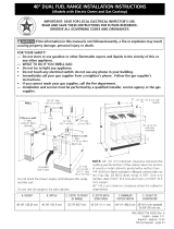
Gas and Electric Supply Zone
2" maximum protrusion
from wall for gas or
electrical supply
Gas & Electrical
Supply Zone
30" (30" models)
36" (36" models)
48" (48" models)
Model A B C
30" 7-1/2" 15-1/8" 7-3/8"
36" 10-7/8" 14-3/8" 10-3/4"
48" 17-1/8" 15-3/8" 15-1/2"
Figure 3a: Gas & Electrical Supply Locations for Dual Fuel Ranges
Note:
If not already present, install gas shut-off valve in an easily
accessible location. Make sure all users know where and
how to shut off the gas supply to the range.
Note:
The installer should inform the consumer of the location of
the gas shut-off valve.
Note:
Any opening in the wall behind the appliance and any
opening in the floor under the appliance must be sealed.
The dual fuel ranges may be connected to the power
supply with a range supply cord kit or by hard-wiring to the
power supply. It is the responsibility of the installer to
provide the proper wiring components (cord or conduit and
wires) and complete the electrical connection as dictated
by local codes and ordinances, and/or the National Electric
Code. The units must be properly grounded. Refer to Step
6 for details.
The range must be connected only to the type of gas
for which it is certified. If the range is to be connected to
propane gas, ensure that the propane gas supply tank is
equipped with its own high pressure regulator in addition to
the pressure regulator supplied with the range. (See
Step 5.)
Note:
The range is designed for nearly-flush installation to the
back wall. For a successful installation, it may be
necessary to reposition the gas-supply line and electrical
cord as the range is pushed back to its final position.
SUGGESTION: This may be accomplished by carefully
pulling on a rope or twine looped around the gas or
electrical supply line as the range is pushed back into
its final installed position.
English 7

Electrical Supply
Installation of the range must be planned so that the rough-
in of the junction box for the receptacle or conduit
connection will allow maximum clearance to the rear of the
unit.
When the power supply cord or conduit is connected to the
mating receptacle or junction box cover, the combined plug/
receptacle or junction box cover/conduit connector should
protrude no more than 2" from the rear wall. See Figure 3b.
Refer to Figure 9 on page 14 for location of junction box on
unit. To minimize binding when the unit is connected to the
receptacle or junction box, orient the receptacle or conduit
connector, and slide back into position.
2" Maximu_
F
L
\
2" Maximum when
plugged in
Power Cord
& Receptacle
Junction Box
&Conduit
Figure 3b: Wall Connection
Step 3: Unpacking and Moving
the Range
CAUTION:
Proper equipment and adequate manpower
must be used in moving the range to avoid
injury, and to avoid damage to the unit or the
floor. The unit is heavy and should be handled
accordingly.
• The range has an approximate shipping weight as
shown in "Chart A". The grates, griddle plate, burner
caps, front kick panel, and oven racks must be
removed to facilitate handling. Removing the door(s) is
also recommended. (See "Step 8: Door Removal and
Reinstallation" on page 18) This will reduce the weight
as shown in "Chart A" and allow the range to pass
through 30" doorways. See Figure 2 on page 6. Do not
remove the griddle element and tray assembly.
• Remove the outer carton and packing material from the
shipping pallet. The dual fuel ranges are held to the
pallet by four (4) bolts (see Figure 4 and Figure 5). The
two front pallet bolts are accessible only after removing
the Kick Panel. The Kick Panel is removed by two
screws below the lower corners of the oven cavity.
After removing the bolts, the range must be lifted and
removed from the pallet.
Note:
Leave adhesive-backed foam layer over brushed-metal
surfaces, to protect finish from scratches, until the range is
installed in its final position.
Important:
DO NOT lift the range by the oven door's handle, as this
may damage the door hinges and cause the door to fit
incorrectly to the oven cavity.
iiiiiiiiiiiiiiiiiiiiiiiii!_i_i_i_i_i_i!i_i!i'_!ii61i_iifii_i_i_i_i_i_i_ii,!i_iiiiiiiiiiiiiiiiiiiiiiiiiiiiiiiiiiiiiiiiiiiililililiiiiiii_i!iiii';ii_ii!ililiiii!ii_i_iiii!81i;_i_i_i_ii_ii_iii_!_iiii_ii_i!_!i_i!iiiilililililililili!i_
,
Shipping Weight 340 Ibs. 450 Ibs. 590 Ibs.
Weight without 290 Ibs. 390 Ibs. 530 Ibs.
packing materials
Without door(s),
burner caps, front kick 220 Ibs. 300 Ibs. 400 Ibs.
panel and oven racks
English 8

Figure 4: Removal of Two Front Shipping Bolts
Shipping ®
Bolt
Figure 5: Removal of Two Rear Shipping Bolts
• Due to the weight, a dolly with soft wheels should be
used to move this unit. The weight must be supported
uniformly across the bottom (See Figure 6).
• After transporting the range by dolly close to its final
location, the range can be tipped back and supported
on the rear legs while the dolly is carefully removed.
THE FLOOR UNDER THE LEGS SHOULD BE
PROTECTED BEFORE PUSHING THE UNiT iNTO
POSiTiON. The anti-tip device must be installed
(Step 4), gas and electrical connections should be
made (Step 5 and Step 6), and the backguard installed
(Step 7) before the range is placed in its final position.
• Do not install the oven door(s) until the range is in its
final location.
Range
Must be
Uniformly
Supported
by Braces
Provided
on Bottom
/43f Range
Figure 6: Dolly Positioning
Remove all tape and packaging before using the
appliance. Destroy the packaging after unpacking the
appliance. Never allow children to play with packaging
material.
Step 4: Installing Anti-Tip
Device
For all 30" and 36" ranges, an anti-tip device must be
installed as per these instructions.
_ ARNING m RANGE TIPPING
HAZARD:
• All ranges can tip and injury can result. To
prevent accidental tipping of the range,
attach it to the floor, wall or cabinet by
installing the Anti-Tip Device supplied.
• A risk of tip-over may exist if the appliance
is not installed in accordance with these
instructions.
• If the range is pulled away from the wall for
cleaning, service or any other reason,
ensure that the Anti-Tip Device is properly
reengaged when the range is pushed back
against the wall. In the event of abnormal
usage (such as a person standing, sitting,
or leaning on an open door), failure to take
this precaution can result in tipping of the
range. Personal injury might result from
spilled hot liquids or from the range itself.
English 9

WARNING m ELECRICAL SHOCK
HAZARD:
• Use extreme caution when drilling holes
into the wall or floor. There may be
concealed electrical wires located behind
the wall or under the floor.
• Identify the electrical circuits that could be
affected by the installation of the Anti-Tip
Device, then turn off power to these
circuits.
• Failure to follow these instructions may
result in electrical shock or other personal
injury.
,_IL WARNING:
• All Ranges can tip.
• Injury to Persons could result.
• Install Anti-Tip Device packaged
with range.
• Verify the that anti-tip device is
engaged.
• See Installation Instructions.
ATTENTION m PROPERTY DAMAGE:
• Contact a qualified installer or contractor to determine
the proper method for drilling holes through the wall or
floor material (such as ceramic tile, hardwood, etc.)
• Do not slide the range across an unprotected floor.
• Failure to follow these instructions may result in
damage to wall or floor coverings.
30 and 36 Inch Ranges
See Figure 7a and Figure 7b.
415078 4 Screw, Phillips, #10 x 1-1/2"
647936 1 Anti-Tip Bracket,
Floor-Mounted
NOTICE:
48" Ranges do not require the Anti-Tip Bracket. This is due
to the size and weight distribution of the 48" models.
Important Installation Information:
• The anti-tip bracket may be attached to a solid wood
cabinet having a minimum wall thickness of 3/4".
• The thickness of the wall or floor may require use of
longer screws, available at your local hardware store.
• In all cases, at least two (2) of the bracket mounting
screws must be fastened to solid wood or metal.
• Use appropriate anchors when fastening the mounting
bracket to any material other than hard-wood or metal.
Tools Needed for Installation of Anti-Tip
Device:
• Screwdriver, Phillips
• Drill, electric or hand
• Measuring tape or ruler
• 1/8" drill bit (wood or metal wall or floor)
• 3/16" carbide-tipped masonry drill bit (concrete or
concrete block wall or floor)
• 3/16" anchors, drywall or concrete, 4 each (not
required if mounting bracket is being attached to solid
wood or metal)
• Hammer
• Pencil or other marker
Figure 7a: Mounting Anti-tip Bracket
English 10

Wall Line
Floor
I
I
I
I
I
--tt
I
Front Edge of I
Right Cabinet I
_/
/
2-t/2"
(typical -
either side)
Figure 7b: Placement of Anti-Tip Bracket (Top View)
Prepare holes at fastener locations as identified below:
• For walls, wall studs, or floors composed of solid
wood or metal, drill 1/8" pilot holes.
• For walls or floors composed of drywall, sheet-rock
or other soft materials, drill 3/16" holes to a mini-
mum depth of 1-3/4", then tap plastic anchors into
each of the holes using a hammer.
• For walls or floors composed of concrete or con-
crete block, drill 3/16" holes to a minimum depth of
1-3/4", then tap concrete anchors into each of the
holes using a hammer.
• For walls or floors havinq ceramic tile coverinq, drill
3/16" holes through the tile only, then drill into the
material behind the tile as indicated immediately
above.
If the range is moved to a new location, the Anti-Tip
Device must be removed and reinstalled.
Mounting Anti-Tip Bracket
The alternative floor mounted bracket shall be installed as
follows:
,
,
3.
Place bracket on floor in position shown in Figure 7b
(Bracket may be used in either corner of the installation
area).
Secure to floor or wall stud.
Later, when the unit is installed, the adjustable leg will
slide under the bracket.
Step 5: Gas Requirements and
Hookup
Verify the type of gas being used at the installation site.
The appliance is shipped from the factory for use with
natural gas. It must be converted for use with propane.
A qualified technician or installer must do the
conversion. Make certain the range matches the type of
gas available at this location.
The field conversion kit for this series of dual-fuel ranges is
Thermador Model PLPKIT. Obey all instructions in this kit
for correct conversion of the gas regulator and settings for
the gas valves.
CAUTION:
When connecting unit to propane gas, make
certain the propane gas tank is equipped with its
own high pressure regulator in addition to the
pressure regulator supplied with the appliance.
The pressure of the gas supplied to the
appliance regulator must not exceed 14" (34.9
mb) water column.
This appliance has been CSA certified for safe operation
up to an elevation of 10,200 ft. without any modifications.
Exception: For use with propane, the appliance must be
converted per the LP conversion instructions.
English 11

Natural Gas Requirements:
Inlet Connection: 3/4" NPT external
1/2" NPT internal
(Minimum 3/4" dia. flex line.)
Supply Pressure: 6" min. to 14" max. water column.
(14.9 to 34.9 mb)
Manifold Pressure: 5" water column (12.5 mb)
Propane Gas Requirements:
Inlet Connection: 3/4" NPT external
1/2" NPT internal
(Minimum 3/4" dia. flex line.)
11"min. to 14"max. water column.
(27.4 mb to 34.9 mb)
10" water column (24.9 mb)
Supply Pressure:
Manifold Pressure:
WARNING:
If a gas conversion kit is used, the kit shall be
installed by a qualified service agency in
accordance with the manufacturer's instructions
and all applicable codes and requirements of the
authority having jurisdiction. If the information is
the instructions is not followed exactly, a fire,
explosion, or production of carbon monoxide
may result causing property damage, personal
injury, or loss of life. The qualified service
agency is responsible for the proper installation
of the kit. The installation is not proper and
complete until the operation of the converted
appliance is checked as specified in the
manufacturer's instructions supplied with the kit.
WARNING:
Gas line must not come in contact with any
components inside back cover of range. Run
gas line in channel in back of range.
Hook Up
• A manual gas shut-off valve must be installed external
to the appliance, in a location accessible from the front,
for the purpose of shutting off the gas supply. The
supply line must not interfere with the back of the unit.
Make sure the gas supply is turned off at the manual
shut-off valve before connecting the appliance.
• The range is supplied with its own pressure regulator
that has been permanently mounted within the range
body.
• Use 3/4" flex line to connect between the gas supply
and the appliance inlet pipe, which exits the upper rear
of the appliance. The appliance pipe connection has a
3/4" NPT external thread and a 1/2" NPT internal
thread. (See Figure 8.) Use caution to avoid crimping
the 3/4" flex line when making bends.
• The gas supply connections shall be made by a
competent technician and in accordance with local
codes or ordinances. In the absence of local codes, the
installation must conform to the National Fuel Gas
Code ANSI Z223.1/NFPA54- current issue.
Always use pipe sealing compound or Teflon® tape on
the pipe threads, and be careful not to apply excessive
force when tightening the fittings.
Leak testing of the appliance shall be in accordance
with the following instructions.
• Turn on gas and check supply line connections for
leaks using a soap and water solution.
• Bubbles forming indicate a gas leak. Repair all
leaks immediately after finding them.
_h= WARNING:
Do not use a flame of any kind to check for
-- gas leaks.
English 12

GasInlet IConnection
Channel
Recess in I
Back Panel,I
for 3/4"Gas
Lne.
CAUTION:
The appliance must be isolated from the gas
supply piping system by closing its individual
manual shut-off valve during any pressure
testing of the gas supply piping system at test
pressures equal to or less than 1/2 psig
(3.5kPa.).
The appliance and its individual shut off valve
must be disconnected from the gas supply
piping system during any pressure testing of the
system at test pressures in excess of 1/2 psig
(3.5kPa.).
When checking the manifold gas pressure, the
inlet pressure to the regulator should be at least
6.0" (14.9 mb) W.C. for natural gas or 11.0"
(27.4 mb) for propane.
Do not attempt any adjustment of the pressure
regulator.
Figure 8: Appliance Manifold Pipe Connection
Step 6: Electrical Requirements, Connection & Grounding
• Prior to servicing appliance, always disconnect appliance electrical supply cord, if so equipped, from wall receptacle. If
appliance is hard-wired to power supply, disconnect power to unit by turning off the proper circuit breaker or
disconnecting the proper fuse. Lock service panel to prevent power from being turned ON accidentally.
Dual Fuel range models can be connected or hardwired to the power supply as described on page 15.
30" 240/208 VAC 35 Amps 60 Hz. Single
36" 240/208 VAC 35 Amps 60 Hz. Single
48" 240/208 VAC 50 Amps 60 Hz. Single
A neutral supply wire must be provided from the power
source (breaker/fuse panel) because critical range
components, including the surface burner spark re-
ignition module, require 120 VAC to operate safely and
properly.
WARNING:
An improper 120/240 VAC power supply will
cause malfunction, damage to this appliance,
and possibly create a condition of shock hazard.
If the correct power supply circuit is not provided, it is
the responsibility and obligation of the installer and
user to have proper power supply connected. This
must be accomplished in accordance with all
applicable local codes and ordinances by a qualified
electrician. In the absence of local codes and
ordinances, the power supply connection shall be in
accordance with the National Electric Code.
Observe all governing codes and ordinances when
grounding. In the absence of these codes or
ordinances observe National Electrical Code ANSI/
English 13

NFPANo.70currentissue.Seethefollowing
informationinthissection(Step6)forgrounding
method.
• Electricalwiringdiagramsandschematicsareattached
behindthetoekickpaneloftherangeforaccessbya
qualifiedservicetechnician.
• Therangesaretobeconnectedtoa240/208VAC
powersupply.
DualFuelmodelsmustbeconnectedtothepowersupply
utilizingoneofthefollowingmethods.Forallmethodsof
connection,thelengthofthecordorconduit/wiringmust
allowtheunittobeslidcompletelyoutofthecabinet
withouthavingtounplugordisconnecttheunitfromthe
powersupply.Recommendedminimumfreelengthofcord
orconduitisfourfeet.Electricalinstallationsandgrounding
mustbeinaccordancewithalllocalcodesandordinances,
and/ortheNationalElectricCode,asapplicable.
4-CONDUCTOR CORD m NORMALLY, A UNIT
MUST BE CONNECTED TO THE POWER SUPPLY
WITH A 3-POLE, 4-CONDUCTOR CORD KIT RATED
125/250 VOLTS, 50 AMPERES, AND MARKED FOR
USE WITH RANGES. The cord kit must be attached to
the range junction box with a strain relief which will fit a
1" diameter hole. If not already equipped, the cord
must have 1/4" faston closed-loop lugs attached to the
free ends of the individual conductors, preferably
soldered in place.
PERMANENT CONNECTION (HARD WIRING) --
Units may be hard wired to the power supply. The
installer must provide approved flexible aluminum
conduit, 3/4" trade size, maximum 6 feet long. Locate
the junction box on the rear of the unit and remove
cover. Refer to Figure 9a or Figure 9b, depending upon
the range model. Remove the ground strap retaining
screw and bend the ground strap up. Refer to
Figure 10. The conduit must be installed to the junction
box using an approved conduit connector.
Wiring for the unit is to be brought into the junction box
through the conduit. The ends of the wiring must have
1/4" faston closed-loop lugs attached, preferably
soldered in place. Make the connections to the terminal
block provided. Secure the ground lead to the junction
box with the screw previously used to secure the
ground strap. Refer to Figure 12. The free end of the
conduit must be connected to a junction box provided
in the gas and electrical supply zone, as shown in
Figure 3a on page 7.
If aluminum supply wiring exists in the installation, splice
the aluminum house wiring with appropriate-thickness
gauge copper wire for adapting to the range, using special
connectors designed and certified for joining copper and
aluminum wire. Follow the connector manufacturer's
recommended installation procedure.
WARNING:
Improper connection of aluminum house wiring
can result in a fire or shock hazard. Use only
connectors designed and certified for
connecting to aluminum wire.
Figure 9a: Location of Junction Box on 30" and 36" Ranges
English 14

Figure 9b: Location of Junction Box on 48" Ranges
The cord kit must be attached to the range junction box
with a strain relief which will fit a 1" diameter hole. If not
already equipped, the cord must have 1/4" faston
closed-loop lugs attached to the free ends of the
individual conductors, preferably soldered in place.
Installer -- show the owner the location of the circuit
breaker or fuse. Mark it for easy reference.
A 3- or 4-conductor supply may be connected to the
terminal block.
3-Wire Lead Connection
1. Remove upper nuts only from the terminal block studs.
Do not remove nuts which secure range internal
wiring leads.
2. Secure the neutral, grounded wire of the supply circuit,
to the center stud of the terminal block with nut. (See
Figure 11).
3. Secure the L1 (black) and L2 (red) power leads to the
outside terminal block studs (brass colored) with nuts.
4. Tighten nuts securely.
UpperNut
)ed Washer
'Wire
Flat Washer
Figure 10: Conductor Securement
3-CONDUCTOR CORD m WHERE LOCAL CODES
AND ORDINANCES PERMIT GROUNDING
THROUGH NEUTRAL, AND CONVERSION OF
SUPPLY TO 4 WIRE IS IMPRACTICAL, UNIT MAY
BE CONNECTED TO THE POWER SUPPLY WITH A
3-POLE, 3-CONDUCTOR CORD KIT RATED 125/250
VOLTS, 50 AMPERES, AND MARKED FOR USE
WITH RANGES.
L1 Black
L2 Red
Neutral White
Figure 11:3 Wire Connection
English 15

4-Wire Connection
,
,
3.
4.
5.
Remove upper nuts only from the terminal block studs.
Do not remove lower nuts which secure range
internal wiring leads.
Remove ground strap screw and bend the strap up as
shown in Figure 12.
Secure the neutral wire to the center stud of the
terminal block with nut.
Secure the L1 (black) and L2 (red) power leads to the
outside terminal studs (brass colored) with nuts.
Secure the bare copper ground lead to the range
chassis using the ground screw previously used for the
ground strap. Be sure that neutral and ground
terminals do not touch.
6. Tighten all connections securely.
Bend Ground Strap Up
O
Figure 12: Ground Strap
L1 Black_"
L2 Red
Neutral Wire
Step 7: Backguard Installation
The backguard must be attached before sliding the range
into the final installed position. A Low Back or Pot-and-Pan
Shelf must be installed when there is less than a 12"
clearance between a combustible back wall and the back of
the range above the cooking surface. (See Figure 2 on
page 6).
An Island Trim is available for covering the backguard area
of the range for island installations; however, the Island
Trim can only be used where there is a minimum of 12"
horizontal clearance between a combustible back wall and
the back of the range. (See Figure 2 on page 6).
Align the back panel of accessory with the flange on the
range side panel right and left rear corners. The backguard
is inserted inside the guide channels on the back of the
range. (See Figure 14.)
Make sure the backguard's front face is outside of the
flange at the back of the range.
Install screws through the backguard's front face panel into
the flange on the range. The 30-inch and 36-inch ranges
will use three (3) screws and 48-inch range will use four (4)
screws.
Install four (4) screws to secure the backguard's back panel
to the guide channels on the back of the range. Install one
(1) screw and spacer to center hole location. (See
Figure 14.)
The spacer is necessary to create proper clearance
between the backguard rear panel and the back wall. The
spacer is not used with the Island Trim.
Figure 13: Secure Neutral Wire
English 16

Rear View
I
t
Spacer
__"FrontaFeaCe
Front of Unit
I
• i\\
WARNING:
Fingers or hand could get pinched when
installing the backguard. Severe injury could
result. Use extreme caution and wear thick
protective gloves to avoid potential cut or
laceration to finger or hand while sliding the
backguard down onto the range.
WARNING:
To avoid possible burn or fire hazard, a
backguard designed specifically for this range
must be installed whenever the range is used.
Backguard
Installed
Figure 14: Backguard Installation
CAUTION"
The Pot and Pan Shelf can get very hot! DO
NOT place the following items on top of the Pot
and Pan Shelf:
• plastics or containers that can melt
• flammable items
• a total load over 30 pounds (13.6kg)
English 17

30" Included N/A HS30R IT30R
36" N/A LB36R HS36R IT36R
48" N/A LB48R HS48R IT48R
Step 8: Door Removal and
Reinstallation
CAUTION:
USE CAUTION WHEN REMOVING THE
DOOR. THE DOOR IS VERY HEAVY.
• Make sure oven is cool and power to oven
has been turned off before removing the
door. Failure to do so could result in
electrical shock or burns.
• The oven door is heavy and fragile. Use
both hands to remove or replace the door.
• Grasp only the sides of the oven door
when removing or replacing it.
• Failure to grasp the oven door firmly and
properly could result in personal injury and
product damage.
• With the door off, never release the levers
and try to close the hinges. Without the
weight of the door, the powerful springs will
snap the hinges closed with great force.
Photo A: Hinge bracket in closed position
To Remove the Oven Door:
1. Open the door fully and use a screwdriver to pry the
hinge clips away from the hinge slots. (See Photo A.)
2. Flip the hinge clip toward you (see Photo B).
3. Close the door until it stops against the hinge clips. The
open hinge clips will hold the door open at a slight
angle.
4. Grasp the door firmly on the ends of the door handle,
and lift the door up. (There will be some spring
resistance to overcome.) When the door is lifted
sufficient to clear the hinge hooks, the door can be
pulled straight out. (See Photo C.)
5. Place the door in a safe and stable location.
English 18
Photo B: Flip hinge clip toward you
/