USE AND CARE
WARNING: DISCONNECT ELECTRICAL POWER SUPPLY AND LOCK OUT
SERVICE PANEL BEFORE CLEANING OR SERVICING THIS UNIT.
MOTOR LUBRICATION
The motor is permanently lubricated. Do not oil or disassemble motor.
CLEANING
TO CLEAN GRILLE:
CAUTION: Plastic parts can be cleaned with mild, soapy water (use a mild
detergent, such as dishwashing liquid) and dried with a soft cloth. Do not
use abrasive cloth, steel wool pads, or scouring powders.
TO CLEAN FAN ASSEMBLY:
Unplug fan assembly. To remove motor plate: Find the single tab on the
motor plate (located next to the receptacle). Push up near motor plate tab
while pushing out on side of housing. Or insert a straight-blade screwdriver
into slot in housing (next to tab) and twist screwdriver. Gently vacuum fan,
motor and interior of housing. METAL AND ELECTRICAL PARTS SHOULD
NEVER BE IMMERSED IN WATER.
SERVICE PARTS/PIEZAS DE SERVICO
INSTRUCCIONES DE OPERACIÓN Y LIMPIEZA
ADVERTENCIA: ANTES DE LIMPIAR O DAR SERVICIO ESTA UNIDAD, DESCONECTE
EL SUMINISTRO DE ENERGÍA Y BLOQUEE EL PANEL DE SERVICIO .
LUBRICACIÓN DEL MOTOR
El motor está permanentemente lubricado. No lubrique ni desmonte el motor.
LIMPIEZA
PARA LIMPIAR LA REJILLA:
PRECAUCIÓN: Las piezas de plástico se pueden limpiar con una solución suave
de agua y jabón (use un detergente suave, como por ejemplo líquido para lavar
vajilla) y séquelas con un paño suave. No use tela abrasiva, almohadillas de
estropajo de acero ni polvos desengrasadores.
PARA LIMPIAR EL CONJUNTO DEL VENTILADOR:
Desenchufe el conjunto del ventilador. Para quitar la placa del motor: Localice la aleta
de la placa del motor (se encuentra junto a el receptáculo). Empuje hacia arriba la
aleta de la placa del motor mientras empuja hacia afuera el costado de la cubierta.
O bien, introduzca un destornillador de punta recta en la ranura de la cubierta (junto
a la aleta) y haga girar el destornillador. Con una aspiradora limpie suavemente el
ventilador, e motor y el interior de la cubierta. NUNCA DEBE SUMERGIR EN AGUA
LAS PIEZAS METÁLICAS NI LAS ELÉCTRICAS.
GARANTIA
WARRANTY
BROAN-NUTONE ONE YEAR LIMITED WARRANTY
Broan-NuTone warrants to the original consumer purchaser of its products that such products will be free from
defects in materials or workmanship for a period of one year from the date of original purchase. THERE ARE NO
OTHER WARRANTIES, EXPRESS OR IMPLIED, INCLUDING, BUT NOT LIMITED TO, IMPLIED WARRANTIES OF
MERCHANTABILITY OR FITNESS FOR A PARTICULAR PURPOSE.
During this one-year period, Broan-NuTone will, at its option, repair or replace, without charge, any product or
part which is found to be defective under normal use and service.
THIS WARRANTY DOES NOT EXTEND TO FLUORESCENT LAMP STARTERS, TUBES, HALOGEN AND
INCANDESCENT BULBS, FUSES, FILTERS, DUCTS, ROOF CAPS, WALL CAPS AND OTHER ACCESSORIES FOR
DUCTING. This warranty does not cover (a) normal maintenance and service or (b) any products or parts
which have been subject to misuse, negligence, accident, improper maintenance or repair (other than by Broan-
NuTone), faulty installation or installation contrary to recommended installation instructions.
The duration of any implied warranty is limited to the one-year period as specified for the express warranty.
Some states do not allow limitation on how long an implied warranty lasts, so the above limitation may not
apply to you.
BROAN-NUTONE’S OBLIGATION TO REPAIR OR REPLACE, AT BROAN-NUTONE’S OPTION, SHALL BE THE
PURCHASER’S SOLE AND EXCLUSIVE REMEDY UNDER THIS WARRANTY. BROAN-NUTONE SHALL NOT BE
LIABLE FOR INCIDENTAL, CONSEQUENTIAL OR SPECIAL DAMAGES ARISING OUT OF OR IN CONNECTION
WITH PRODUCT USE OR PERFORMANCE. Some states do not allow the exclusion or limitation of incidental or
consequential damages, so the above limitation or exclusion may not apply to you.
This warranty gives you specific legal rights, and you may also have other rights, which vary from state to state.
This warranty supersedes all prior warranties.
To qualify for warranty service, you must (a) notify Broan-NuTone at the address or telephone number below, (b)
give the model number and part identification and (c) describe the nature of any defect in the product or part. At
the time of requesting warranty service, you must present evidence of the original purchase date.
Broan-NuTone LLC, 926 W. State Street, Hartford, Wisconsin 53027 www.broan.com 800-558-1711
1
3
8
6
9
10
2
11
7
4
5
12
99043689C
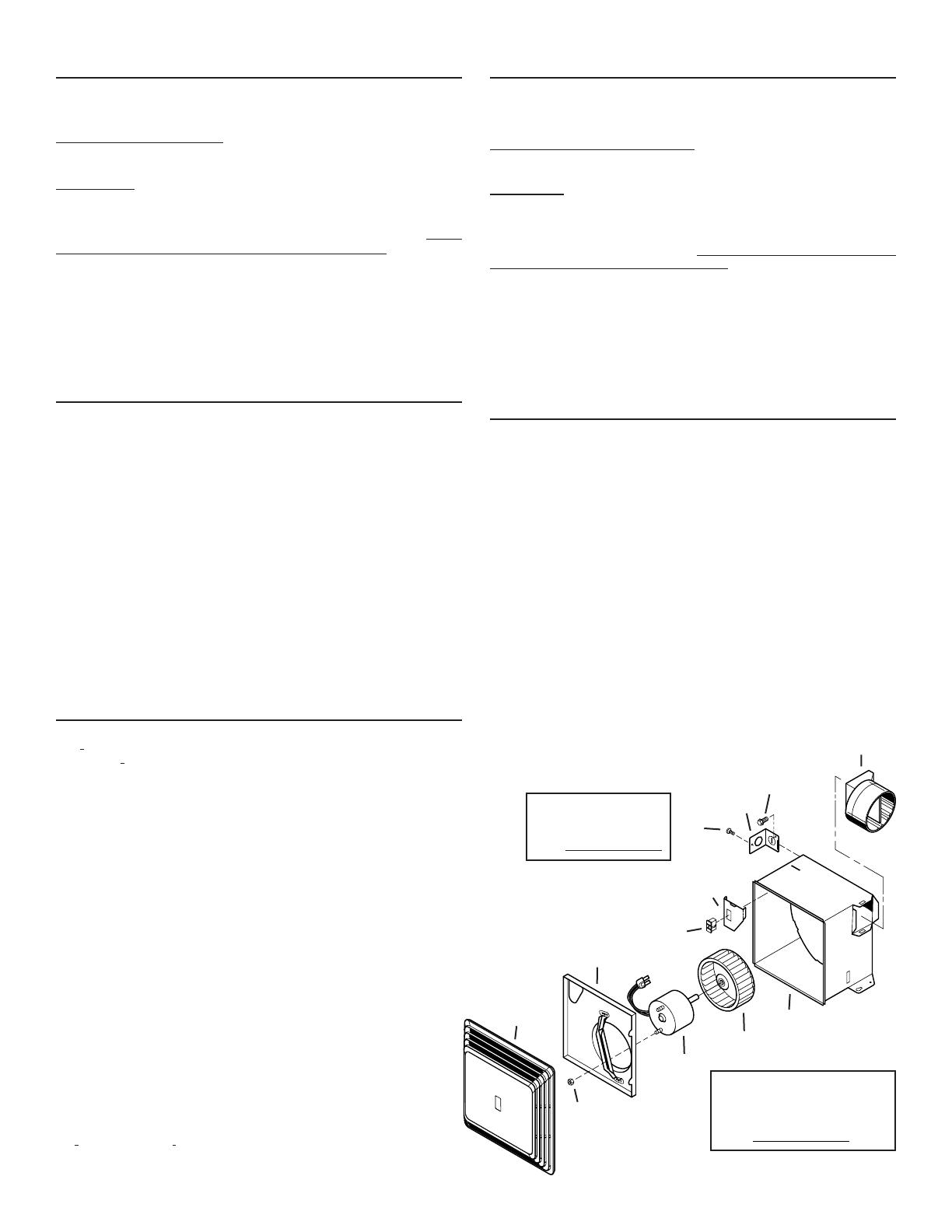
KEY
N
o
. PART NO.
CLAVE N
o
. PIEZA. DESCRIPTION/DESCRIPCIÓN
1 97013576 Grille/Rejilla
2 97018310 Motor Plate/Placa del motor (576)
97014926 Motor Plate/Placa del motor (676, 684)
3 99080656 Motor (576)
99080517 Motor (676)
99080518 Motor (684)
4 99020300 Impeller/Pistón impulsor (576)
99020276 Impeller/Pistón impulsor (676, 684)
5 99260425 Motor Nut (2 req.)/Tuerca del motor (se req. 2)
* 97018554 Blower Assembly (576) (includes Key Nos. 2 thru 5)
Conjunto del ventilador (576) (incluye Clave Nos. 2 de a 5)
* 97015157 Blower Assembly (676) (includes Key Nos. 2 thru 5)
Conjunto del ventilador (676) (incluye Clave Nos. 2 de a 5)
* 97015159 Blower Assembly (684) (includes Key Nos. 2 thru 5)
Conjunto del ventilador (684) (incluye Clave Nos. 2 de a 5)
6 99270982 Receptacle/Receptáculo
7 98009611 Wire Panel/Panel del cableado
* 97015170 Wire Panel Assembly (includes Key Nos. 6 & 7)
Conjunto del panel de cableado (incluye Clave No. 6 & 7)
8 97014922 Housing/Cubierta
9 97003932 Damper/Duct Connector/Conector del regulador de
tiro/conducto
10 98008868 Wiring Plate/Placa de conexiones
11 99150245 Screw, #8-18 x .375/Tornillo, #8-18 x .375
12 99150471 Ground Screw/Tornillo de conexión a tierra
* Not shown assembled.
Order replacement parts by “PART NO.” - not by “KEY NO.”
* No ilustrado ensamblado. Pida piezas de servicio dando como referencia
el N
o
. DE PIEZA, no el N
o
. DE CLAVE.
GARANTÍA BROAN-NUTONE LIMITADA POR UN AÑO
Broan-NuTone garantiza al consumidor comprador original de sus productos que dichos productos carecerán
de defectos en materiales o en mano de obra por un período de un año a partir de la fecha original de compra.
NO EXISTEN OTRAS GARANTÍAS, EXPLICITAS O IMPLÍCITAS, INCLUYENDO, ENTRE OTRAS, GARANTÍAS
IMPLÍCITAS DE COMERCIALIZACIÓN O APTITUD PARA UN PROPÓSITO PARTICULAR.
Durante el período de un año, y a su propio criterio, Broan-NuTone reparará o reemplazará, sin costo alguno,
cualquier producto o pieza que se encuentre defectuosa bajo condiciones normales de servicio y uso.
LA PRESENTE GARANTÍA NO CUBRE LOS TUBOS FLUORESCENTES NI SUS ARRANCADORES, BOMBILLAS
DE HALÓGENO E INCANDESCENTES, FUSIBLES, FILTROS, CONDUCTOS, TAPONES DE TECHO O PAREDES Y
DEMÁS ACCESORIOS PARA CONDUCTOS. Esta garantía no cubre (a) mantenimiento y servicio normales o (b)
cualesquiera productos o piezas que hayan sido utilizados de forma errónea, negligente, que hayan causado
un accidente, o que hayan sido reparados o mantenidos inapropiadamente (por otras compañías que no sean
Broan-NuTone), instalación defectuosa, o instalación contraria a las instrucciones de instalación recomendadas.
La duración de cualquier garantía implícita se limita a un período de un año como se especifica en la garantía
expresa. Algunos estados no permiten limitaciones en cuanto al tiempo de vencimiento de una garantía implícita,
por lo que la limitación antes mencionada puede no aplicarse a usted.
LA OBLIGACIÓN DE BROAN-NUTONE DE REPARAR O REEMPLAZAR, SIGUIENDO EL CRITERIO DE BROAN-
NUTONE, DEBERÁ SER EL ÚNICO Y EXCLUSIVO RECURSO LEGAL DEL COMPRADOR BAJO ESTA GARANTÍA.
BROAN-NUTONE NO SERÁ RESPONSABLE POR DAÑOS INCIDENTALES, CONSECUENTES, O POR DAÑOS
ESPECIALES QUE SURJAN A RAÍZ DEL USO O DESEMPEÑO DEL PRODUCTO. Algunos estados no permiten la
exclusión o limitación de daños incidentales o consecuentes, por lo que la limitación antes mencionada puede
no aplicarse a usted.
Esta garantía le proporciona derechos legales específicos, y usted puede también tener otros derechos, los cuales
varían de estado a estado. Esta garantía reemplaza todas las garantías anteriores.
Para calificar para la garantía de servicio, usted debe (a) notificar a Broan-NuTone al domicilio o al número de
teléfono que se menciona abajo, (b) dar el número del modelo y la identificación de la pieza, y (c) describir la
naturaleza de cualquier defecto en el producto o la pieza. En el momento de solicitar servicio cubierto por la
garantía, usted debe de presentar un comprobante con la fecha original de compra.
Broan-NuTone LLC, 926 W. State Street, Hartford, Wisconsin 53027 www.broan.com 800-558-1711
Las piezas de recambio
se pueden ahora pedir en
nuestro Web site. Visítenos
por favor en
www.Broan.com
Replacement parts can
now be ordered on our
website. Please visit
us at www.Broan.com


