NOTICE TO INSTALLER: Place this label close to the valve where the
owner will see it, such as inside the door of a cabinet or vanity.
WARNING
Water temperature changes due to seasonal or other inlet variations, such as changing the setting
on the hot water heater may require adjustment of the rotational limit stop (13/14/17 Series) or
temperature knob (17T Series) on your tub/shower valve to ensure a safe maximum temperature.
These valve series do not automatically adjust for inlet temperature changes. If changes occur and
you are not sure how to make the necessary rotational limit stop or temperature knob adjustments,
please consult the installation instruction sheet provided with this valve or call 1-800-345-DELTA.
These valve series are designed to minimize the effects of outlet water temperature changes
due to inlet pressure changes, commonly caused by dishwashers, washing machines, toilets and
the like.
They may not provide protection from hot water burns when there is a failure of
other temperature controlling devices elsewhere in the plumbing system.
After making the
necessary adjustments please fill in the information below. This valve/system has been set by the
person listed below to ensure a safe maximum temperature. Any change in the setting may raise
the discharge temperature above the limit considered safe and could lead to hot water burns. If
this label has not been completed, you should verify that the rotational limit stop or temperature
knob has been properly adjusted to suit your individual installation. The installation instruction sheet
supplied with the valve provides information on how to make this setting.
AVISO AL INSTALADOR: Coloque esta etiqueta cerca de la válvula donde el propietario la
pueda ver, tal como dentro de la puerta del gabinete o el tocador.
AVISO:
Los cambios de temperatura del agua por variaciones estacionales u otras variaciones en el agua
de entrada, como el cambio por el ajuste en el calentador de agua, puede requerir el ajuste del
tope del límite rotacional (Series 13/14/17) o ajuste de la perilla para el control de la temperatura
(Series 17T) de la válvula de su unidad bañera/regadera para asegurar una temperatura máxima
segura. Esta serie de válvulas no se ajusta automáticamente para los cambios de temperatura del
agua de entrada. Si cambios ocurren y usted no está seguro como hacer los ajustes necesarios
con la perilla para controlar la temperatura, por favor consulte la hoja de instrucciones de
instalación proporcionada con esta válvula o llámenos al 1-800-345-DELTA. Las válvulas de esta
serie están diseñadas para minimizar los efectos por cambios de temperatura en el agua de
entrada por cambios en la presión del agua, comúnmente causados por el uso simultáneo de
fregadoras de platos, lavadoras, inodoros y aparatos similares.
Estas pueden no proporcionar
protección de quemaduras por el agua caliente cuando hay una falla de otros mecanismos
que controlan la temperatura del agua en otro sitio del sistema de plomería.
Después de
hacer los ajustes necesarios, por favor escriba la información suministrada a continuación. Esta
válvula/sistema ha sido ajustada por la persona indicada a continuación para ayudar a asegurar
una temperatura máxima segura. Cualquier cambio al ajuste puede aumentar la temperatura del
agua de descarga sobre el límite considerado seguro y puede resultar en quemaduras por agua
caliente. Si esta etiqueta no se ha llenado, debe vericar si el control o tope del límite rotacional o
la perilla que controla la temperatura han sido correctamente ajustadas al gusto de su instalación
individual. La hoja de instrucciones de instalación proporcionada con las válvulas le suministra
información sobre como hacer este ajuste.
AVIS À L’INSTALLATEUR: Fixez cette étiquette près du robinet, à la vue à l’intérieur
du propriétaire, de la porte du meuble ou de la coiffeuse, par exemple.
ATTENTION :
Les modifications de la température de l’eau attribuables au changement de saison ou à d’autres
facteurs, comme la modification du réglage du chauffe-eau, peuvent nécessiter un réglage de la
butée de température maximale (séries 13/14/17) ou du bouton de température (séries 17T) de la
soupape de votre robinet pour baignoire et de douche. La soupape de robinet de ces séries ne se
règle pas automatiquement en fonction des changements de température de l’eau chaude de l’eau
d’alimentation. En cas de modification de la température de l’eau d’alimentation, si vous ne savez
pas comment régler la butée de température maximale ou le bouton de température, veuillez consulter
le feuillet d’instructions d’installation fourni avec la soupape ou appeler au 1-800-345-DELTA.
La soupape de cette série est conçue pour limiter la variation de la température de l’eau pouvant
résulter des uctuations de température et de pression dans la tuyauterie d’alimentation. Ces uctuations
sont habituellement causées par une utilisation simultanée du lave-vaisselle, de la machine
à laver, d’un cabinet d’aisances ou d’un autre appareil qui consomme de l’eau.
La soupape peut
ne pas protéger l’utilisateur contre l’ébouillantage en cas de défectuosité d’un autre dispositif
de régulation de la température de l’eau situé ailleurs dans la tuyauterie.
Après avoir
effectué les réglages nécessaires, veuillez inscrire l’information requise ci-dessous. Cet appareil
de robinetterie a été réglé par la personne dont le nom figure ci-dessous pour que la température
maximale de l’eau soit sans danger. Toute modification du réglage peut occasionner une élévation
de la température de l’eau à la sortie du robinet et l’eau qui s’écoulera pourra être suffisamment
chaude pour causer l’ébouillantage. Si la présente étiquette n’a pas été remplie, assurez-vous
que la butée de température maximale ou le bouton de température a bien été réglé en fonction
des caractéristiques de votre installation. La marche à suivre pour faire le réglage figure dans les
instructions d’installation fournies avec la soupape.
BY/POR/PAR _______________ COMPANY/COMPANIA/COMPAGNIE ________________
DATE/FECHA/LE ___________ PHONE/TELÉFONO/TELÉPHONE ____________________
TO BE FILLED OUT BY THE INSTALLER / PARA SER LLENADO POR EL INSTALADOR /
A REMPLIR PAR L’INSTALLATEUR:
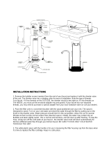
Rotational Limit Stop is
located behind the disc.
13 / 14 Series
Hotter
Más
Caliente
Plus
Chaud
1st Position
Primera Posición
1ère Position
17 Series
Hotter
Más
Caliente
Plus
Chaud
Colder
Más
Fría
Plus
Froid
17T Series
Temperature Knob
Pomo para el ajuste
de temperatura
Bouton de Température
Hotter
Más
Caliente
Plus
Chaud
1st Position
Primera Posición
1ère Position
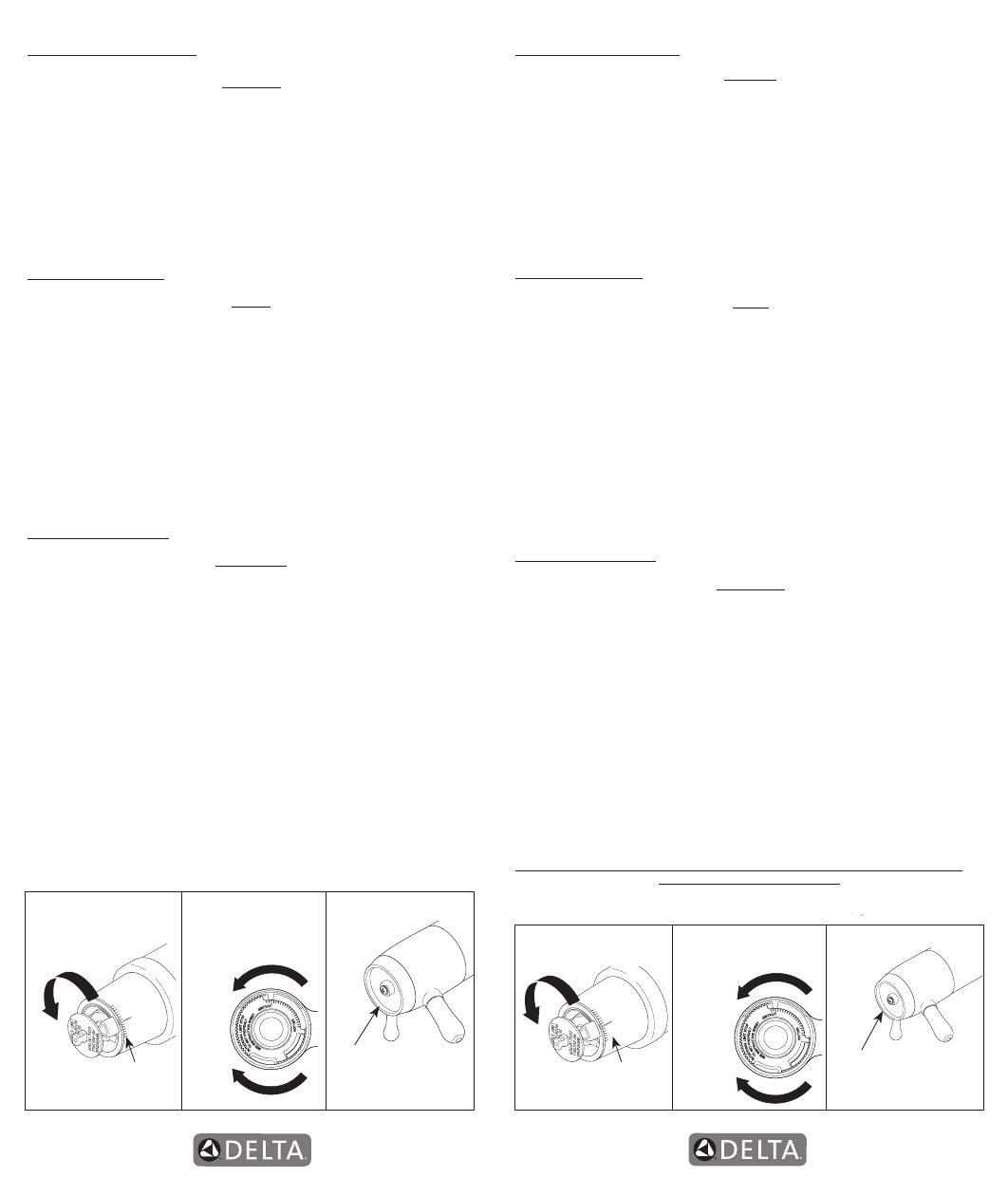
Rotational Limit Stop is
located behind the disc.
13 / 14 Series
17 Series
17T Series
Hotter
Más
Caliente
Plus
Chaud
Colder
Más
Fría
Plus
Froid
Temperature Knob
Pomo para el ajuste
de temperatura
Bouton de Température
NOTICE TO INSTALLER: Place this label on the water heater
next to the temperature adjustment knob.
WARNING:
These series of tub/shower valves do not adjust automatically for changes
in temperature at the hot water heater or inlet.
If the temperature setting of the
hot water heater or inlet is changed, the setting on these valves
must be adjusted
manually!
Failure to re-adjust the valve may result in hot water burns or extreme
cold resulting from variations in line pressure (such as when a dishwasher or washing
machine is in use while you are taking a shower). After installation, verify that the
rotational limit stop (13/14/17 series) or temperature knob (17T series) on the valve
is set so that changes in line pressure or temperature do not result in uncomfortable
water temperature changes.
If the temperature setting of the hot water heater or
inlet is changed after installation of the valve, the setting of the rotational limit
stop or temperature knob also must be changed!
Consult the installation instruction
sheet for instructions on how to make this setting, or call us at 1-800-345-DELTA.
AVISO AL INSTALADOR: Coloque esta etiqueta en el calentador de agua al lado
de la perilla para el ajuste de temperatura.
AVISO:
Esta serie de válvulas para bañeras/regaderas no se ajustan automáticamente a
los cambios de temperatura en el calentador de agua o en el agua de entrada.
Si
el ajuste de la temperatura del calentador de agua o la temperatura del agua que entra
cambia
¡El ajuste de estas válvulas se debe hacer manualmente!
El no reajustar
la válvula puede resultar en quemaduras por agua caliente o temperaturas de agua
extremadamente frías resultando en variaciones de presión y temperatura (como cuando
el fregador de platos o la lavadora están funcionando mientras que se baña). Después
de la instalación, verique que el control o tope del límite rotacional (series 13/14/17) o
la perilla del control de temperatura (series 17T ) en la válvula está ajustada para que
los cambios de presión y de temperatura en la línea no resulten en cambios incómodos
de temperatura del agua.
Si el ajuste de la temperatura del calentador de agua o de
la entrada de agua se cambia después de la instalación de la válvula, el ajuste del
tope del límite rotacional o la perilla de ajuste ¡también se debe cambiar!
Consulte
con su hoja de instrucciones de instalación para saber como se ajusta o cambia el
ajuste, o llámenos al 1-800-345-DELTA.
AVIS À L’INSTALLATEUR: Fixez cette étiquette sur le chauffe-eau près du bouton
de réglage de température.
ATTENTION :
La soupape de robinet de baignoire ou de douche de cette série ne se règle pas
automatiquement en fonction des changements de température de l’eau chaude
au chauffe-eau ou de l’eau d’alimentation.
En cas de modification du réglage de
température du chauffe-eau ou de la température de l’eau d’alimentation, le réglage
de cette soupape doit
être modié manuellement!
Si le réglage de la soupape n’est
pas modifié, le robinet pourra permettre l’écoulement d’eau très chaude susceptible
de causer l’ébouillantage ou d’eau très froide, sous l’effet des variations de pression
et de température dans la tuyauterie d’alimentation (lorsque la douche est utilisée
en même temps que le lave-vaisselle ou la machine à laver, par exemple). Après l’
installation, assurez-vous que la butée de température maximale (séries 13/14/17)
ou le bouton de température (séries 17T) sur la soupape est réglé de manière que
les fluctuations de pression et de température dans la tuyauterie d’alimentation n’
entraînent pas de changements de température de l’eau inconfortables.
En cas de
modication du réglage de température du chauffe-eau ou de la température de
l’eau d’alimentation après l’installation de la soupape, le réglage de la butée de
température maximale ou du bouton de température doit être modié!
Pour régler
le bouton de température, consultez la feuille d’instructions d’installation ou appelez-
nous au 1-800-345-DELTA.